Real-Time Color Quad Processor Model SLX912 Owner’s Manual 15540 Herriman Blvd. Noblesville, IN 46060 - Customer Support 1-800-774-0284 www.security-labs.
Version: 1.0 DMS/MBR CONTENTS 1. INTRODUCTION AND FEATURES ................................................................................................................................. 3 1.1 Product Introduction........................................................................................................................................................ 3 1.2 Product Features .......................................................................................................................
1. INTRODUCTION AND FEATURES 1.1 Product Introduction This surveillance unit can be installed in many different places such as: (homes, shops, offices, etc.). It is designed with four objectives; to be Economical, Functional, Easily Installed, and User Friendly? 1.2 Product Features ??An economic solution for home, shop or building surveillance system. ??Plug & Play - Installs easily and is suitable as DIY (Do It Yourself). ??Equipped with Microprocessor, compact dimension and smart functions.
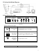
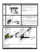
2.1 System Installation Diagram 2.2 Installation Procedure COM/NO/NC MONITOR QUAD OUT OUT POWER IN VIDEO IN RELAY OUT VIDEO OUT VCR IN DC 12V 4 3 2 1 Back Panel §Terminal Function Description. Terminal DC 12V DC Power Input DC POWER INPUT terminal: 12Vdc±10%. Jack COM/NO/NC MONITOR OUT Function Description Alarm Triggered Alarm output N.O. (Normally Open) or N.C. (Normally Relay Output Closed) used to trigger a security video recorder.
QUAD OUT VCR IN Video signal This is the video signal output for connecting to an external output BNC type VCR. Terminal External video signal input BNC This is the video signal input for connecting to an external type Terminal VCR. from the VCR CH1 video signal This is the video signal input for connecting from an input BNC type external camera. Terminal 1 CH2 video signal This is the video signal input for connecting from an input BNC type external camera.
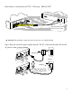
Item Diagram Setup Expatiation Specifications of the Connector Wires: SOLID WIRE ??Insulator stripped off length: 8.5 +0.5 / -1.5? ? ??Maximum gauge: ? =2.3? ( 14~ 24AWG) ? 2.3.3or a STRANDED 2.3.3- R C E O L AY M OU O / N / Connect the external VCR system line (External VCR Start Record) into the RELAY OUT terminal. T N C From b VCR…ect. or ( ? Please check your Time-Lapse VCR or DVR user’s manual for configurations on “RELAY OUT” terminal connections. Please take note on COM-N.O.
Shown below is an illustration of CCTV/ VCR setup - "RELAY OUT". OR N IT MO T OUT OU LAY C RE / NO /N CO M “External Start Record” connector on the VCR ? Attention! The maximum voltage and current for the relay out is DC24V/2Amp. Step 3: Plug one end of the power adaptor into the "DC IN" socket and the other end into the AC power socket as shown below.
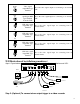
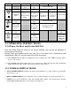
3. OPERATING INSTRUCTIONS 3.1 Introduction to the MASTER CONTROL panel 1 2 3 4 QUAD AUTO ¡ ö ¡ ÷ ¡ Ï 1 2 3 ¡ Ð 4 NEXT PAGE PLAY MENU ?FREEZE Front Panel? Operation Key Function Descriptions. Mode Light Normal Mode Key QUAD LED light 1 2 3 4 QUAD ?FREEZE AUTO ¡ ö 1 ¡ ÷ 2 ¡ Ï 3 Mode Enter to QUAD Display mode. ?FREEZE AUTO Seq. Mode QUAD LED flash QUAD LED light AUTO LED light QUAD LED light Disengage from image freeze mode. QUAD LED light Enter to AUTO Sequential mode.
Light Key ¡ Ð 4 PLAY NEXT PAGE MENU Mode 4 LED light CH4 Full display. QUAD LED flash 4 LED light or dark Freeze / Release CH4 image. Mode AUTO LED light 4 LED light FREEZE Mode PLAY LED light 4 LED light MENU LED light 4 LED light (AUTO LED dark) Enter to 2?2 Freeze / Release Decrease value. Back to normal image display of 2?2 image of CH4 Full quadrant 4. quadrant 4. display. PLAY LED light PLAY LED light PLAY LED dark Enter to VCR PLAYBACK mode.
? FREEZE the Channel: Press key [1~4], the 1~4 LED will turn on and freeze the image. To unfreeze, press? QUAD? key again or wait until the FREEZE HOLD TIME period you have set elapses. ? PIP / POP DISPLAY: Displays Channels 1~4 PIP or POP on the monitor by pressing the function keys [1~4] to display images. Follow the PIP / POP display setup on page 14. 3.2.2 SEQUENCE MODE. ? Press the? AUTO? key to enter AUTO SEQUENCE mode.
? Press key [1 ~ 4 ] again in 2 ?2 zoom image display, the processor will then freeze1 ~ 4 quadrant 2 ? 2 zoom image and the message “FREEZE” will be shown on the monitor. To unfreeze, press? QUAD? function key, or press key [1 ~ 4 ] again. 3.2.4 SYSTEM SETUP. 3.2.4.1 SYSTEM SETUP DESCRIPTION. ??Press the? MENU? function key to enter the MENU page (shown by Figure 1). ??Press the« ? » and« ? » buttons to change the field left and right.
Figure 2. DATE / TIME display location ? When the MONITOR OUT DATE / TIME is set to “ON”, the DATE / TIME will be shown on the MONITOR OUT display. ? When the VCR OUT DATE / TIME is set to “ON”, the DATE / TIME will be shown on the QUAD OUT display. ? SEQUENCE: There are eight positions to select and setup the random switching sequence. Where: Q? QUAD display; 1? CH1 Full display; 2? CH2 Full display; 3? CH3 Full display; 4 ? CH4 Full display; ? Skip.
Figure 3. ? BRIGHT: Adjusts image brightness per channel [1~4]. The brightness range: 0~99. ? CONTRAST: Adjusts image contrast per channel [1~4]. The contrasts range: 0~99. ? HUE: Adjusts image hue (color saturation) per channel [1~4]. The HUE range: 0~99. 3.2.4.4 TITLE SETUP. .... CH1: CH2: CH3: CH4: TITLE SETUP .... ON CAMERA01 ON CAMERA02 ON CAMERA03 ON CAMERA04 CHARACTER COLOR: WHITE Figure 4.
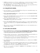
3.2.4.5 MOTION SETUP. MOTION SETUP POWER ON MOTION AUTO OFF SENS MD.NUM RE DET CH1: 70 03 64 OFF AREA CH2: 70 03 64 OFF AREA CH3: 70 03 64 OFF AREA CH4: 70 03 64 OFF AREA BUZZER ALARM TIME: 3 SEC RELAY OUT TIMER: Figure 5. 8 SEC FREEZE HOLD TIMER: 30 SEC ? POWER ON MOTION AUTO OFF (ON): After power on auto, disable all motion (OFF setting) or enable all motion (ON setting). ? SEN (Sensitivity): Control Threshold value. Range: 10 ~ 99, 99 has a higher sensitivity rate than 10. ? MD.NUM (Detected window No.
??Press the« + » or« - » buttons to change the cursor up and down. Pressing them more than 1 second allows the cursor to change quickly up and down. ??Button« AUTO» is used for enabling (green window) or disabling (clear window) a detection window. . ??Button« QUAD» is used for enabling (green windows) or disabling (clear window) the rows of detection windows (it is done per row). ??Button« PLAY» is used for enabling (green window) or disabling (clear window) all detection windows.
? PIP – Places a small video image from a single channel within the Full Screen Display of the listed channel. Allows user to view 2 channels at once. ? POP – Places a small video image from the remaining 3 channels within the Full Screen Display of the listed channel. Allows user to view all channels at once. ? SON – The number of the channel being placed within the Full Screen Display of the listed channel.
P: 01 NO AT CH YY.MM.DD HH\MM\SS ........................ P: 01 NO AT CH YY.MM.DD HH\MM\SS ......................... 01 VL 2 2003.08.25 12:35:07 02 MD 3 2003.08.25 15:05:32 03 MD 1 2003.08.26 09:52:46 04 VL 4 2003.08.27 18:22:21 NO ALARM RECORD... LAST ALARM LIST ERASER AT:2003.08.27 12:37:10 Figure 8: Alarm event list Figure 9: Alarm message after Load Default & Clear Alarm List operation. 3. Press the« + » or« - » buttons to skip to the front or next page. 4.
4. PRECAUTIONS 1. Keep away from moisture, fire, and vibration. Do not remove the cover to avoid the risk of electric shock. 2. Keep the temperature between -10? ~50? , relative humidity lower than 85%. 3. Keep the unit well ventilated. Do not stack anything on the top of this processor. 4. Please do not use any other power adapter but the one supplied with this unit. It is strictly prohibited to insert any other plug into the DC IN socket, use only the specified DC12V±5% / 1.0A power adapter. 5.
Security Labs Limited Warranty Security Labs, Inc. warrants that if a Security Labs product proves to be defective in material or workmanship under normal usage, Security Labs will provide without charge to the consumer, parts and/or labor necessary to remedy the defect for the period of ONE YEAR from the date of purchase. The warranty period commences on the date that the product is purchased by the consumer. Any implied warranty is also limited to the duration above.