
Installation manual


6
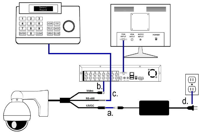
WIRING CONNECTIONS
a. Connect the power supply’s 12VDC plug to the camera’s
power jack.
b. Connect the camera’s BNC connector to a DVR (or monitor)
with a 75Ω coaxial video cable.
c. Connect unshielded twisted pair wire (UTP) between the
camera’s RS485 wires and the PTZ controller. The purple
wire is positive (A, +) and the grey wire is negative (B, -). Be
sure the same polarity is used at each end of the connection.
d. Connect the power supply’s AC plug to a suitable AC wall
outlet.