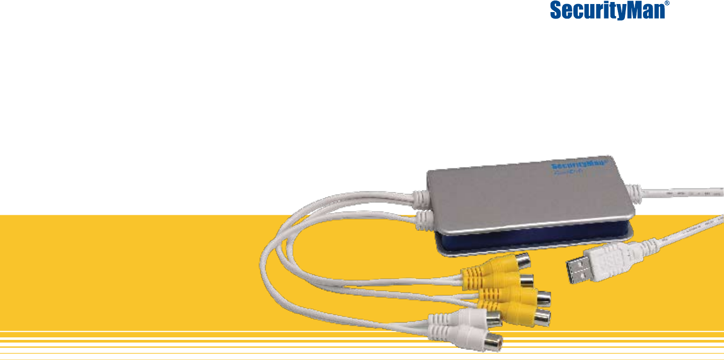
iCamDVR User’s Manual Easily turn Security camera into an Internet Security WebCam! USB Internet Camera & DVR Convertor Box
Copyright Notice This manual is furnished under license and may be used or copied only in accordance with the terms of such license. Except as permitted by such license , no part of this publication may be reproduced , stored in a retrieval system , or transmitted , in any form or any means , electronic , mechanical . Recording, or otherwise, including translation to another language or format, without the prior written permission of SecurityMan.
Table of Contents Introduction iCamDVR product features System Requirements iCamDVR Specifications System Setup 6 8 9 Basic Configuration Panel Dwell Interval Caption Resolution Hardware Driver Software Installation iCamDVR Windows Vista/7 Driver Software Installation Windows Vista/7 Driver Software Uninstall Windows 2000/XP Driver Software D-Interlace 10 10 14 15 Live Audio Storage Disk Internet Config Record Setup Panel Time Stamp Main Display Interface Display Control Panel Display Control Panel
Motion Detection configuration Panel Set Motion Detection Sensitivity Alarm Configuration Panel Disk Shortage Alarm Pre-Alarm Record Motion Holding Time Alarm Output Function Configuration Auto Mail Alarm Function Configuration Emap Function Configuration Emap Edit To view the Emap P.T.
Using SuperCam Live View Image Playback Video Playback Server List Settings Storage Display Alarm Log Information Help Log Off Android SuperCam Application Windows Mobile Connection Symbian 60 Series Connection BlackBerry Connection 64 65 66 67 67 68 68 68 68 68 69 69 69 70 73 74 77 Frequently Asked Questions Installation Q & A SuperDVR Q & A Network Q & Other Q & A 5 | SecurityMan 82 83 85 86 Troubleshooting System requirements for iCamDVR & Remote Client Computers Installation Instruction: Troublesho
Introduction Thank you for choosing iCamDVR! The iCamDVR system is a 4 channel USB Internet camera and DVR adapter which implements MPEG4 compression format and enables 4 channel real-time/time-laps surveillance. iCamDVR has a powerful compression rate and other network features in which synchronous audio/ video compression transmission. It is widely used in banks, intelligent communities, traffic management units, medical department buildings, educational buildings, armed forces, etc.
• • • Users Management There are 3 level of users privileges; Administrator, Power Users, and Normal Users. Different users have different rights to ensure system security and accessibility. Multi-Channel Display Support different multi-channel display mode, full screen display and auto dwell display. Watch Dog Function In case SuperDVR driver or windows system is froze or lock up, the watchdog feature will automatically restart the computer and automatically login to SuperDVR system.
System Requirements iCamDVR Minimum System Requirements is shown as Table1. PC Module Type iCamDVR CPU Intel P4 Celeron Processor 1.7GHz Motherboard Intel 845/865/915 series HDD 80GB Free RAM 256MB VGA GeForce2_GeForce4_FX5200_ATI Rage128 OS Windows 2000 SP4, 2003 SP1, XP SP2, Vista, & 7 (32-bit/64-bit) DirectX 9.0 or above USB 2.
iCamDVR Specifications • • • • • • • • • • • • • • • Video format: NTSC/PAL (selectable). Resolution: 320x240/ 640x480(NTSC), 352x288/ 704x576(PAL). Maximum Frame rate per channel: 30 ftp (NTSC) 4 channels; 7.5fps each channel (option), 25 fps (PAL) 4 channels; 6.25fps each channel. Screen set: resolution 1024_768, color quality 16 bits or 32 bits @ 96% DPI Video Resolution: 320x240 or 640x480 (NTSC) Compression code rate: 50kbps – 1.
Hardware DRIVER SOFTWARE INSTALLATION iCamDVR Windows Vista/7 Driver Software Installation USB Connection to computer Plug in iCamDVR hardware to the computer via USB2.0 port. Insert the auto run CD into the CD/DVD ROM tray to automatically install the driver software and the following windows will appear: Support Windows 2000, XP, Vista, 7(32-bit/64bit) OS Figure 2 - iCamDVR Installation Select and click on “Install or run program” to continue installation.
Click “Next” to proceed. Figure 3 - Installation Selection Figure 5 - Welcome Page Next click on “Install SuperDVR” and the installation process start with User Account Control windows, please select “Cancel” to quite installation or select “SuperDVR. EXE Unknown Publisher“ (Windows 7) or select “Allow I trust this program. I know where it’s from or I’ve used it before.” to continue installation as illustrated below. Setup Type windows Select to setup “NTSC or PAL” video standard, for U.S.
Setup start to install the necessary driver software files as follow. Figure 7 - Rate of progress of driver installation Figure 9 - Program Compatibility Assistant If the iCamDVR hardware is not connected to the computer or has loose connection with the computer, in such case the following windows will appears during driver software installation: Click “Cancel” to temporary cancel the installation process.
Choose a Destination Location click on “Browse” to select path other than the default path or click “Next” to continue using the default path (recommended). Figure 13 - Install Process Figure 11 - Select Installation Pass Select Program Folder Setup click “Next” to continue installation. Figure 12 - Register Application 13 | SecurityMan Click “Finish” and restart the computer to complete driver software installation.
After the computer restart, go to device manager to ensure the hardware installation for iCamDVR exist under Sound, Video, and Game Controllers as circled below. NOTE • iCamDVR require PCs with USB 2.0 Host Controller. • To disconnect or eject iCamDVR from the computer: Left click on the Safely Remove Hardware icon on the “Taskbar -> Safely Remove iCamDVR Video/Audio Card”.
A second method is to go to Windows Vista/7 Programs and Features to double click on “SuperDVR” and then follow the uninstall instructions process. Windows 2000/XP Driver Software Installation/Uninstallation Please reference the above Windows Vista driver software installation. To uninstall SuperDVR driver software in windows 2000/XP, please go to, “Control Panel > Add or Remove Programs”, and click or select “SuperDVR” to Change/Remove it.
Main Display Interface Execute SuperDVR program, then input in the default user and password to get to the main display interface as shown below: The display control panel is located at the bottom of the main display/graphic interface, and includes Screen 1, Screen 4, Auto Dwell, Next Page, Free Space Blue Bar, Capture, and Urgent Record active buttons.
Quick Channel Display Switch In Screen 4 display mode, left click on any of the four cameras image, the display will switch from 4 screen display to a single channel display view. Then right click on the single channel image to switch to a full screen display view without the GUI (Graphic Users Interface), right click again to switch back to the GUI with single channel display view and then left click again to switch back to original Screen 4 display.
NOTE It is strongly recommended that the default user name and password be change by the system administrator of iCamDVR. Figure 23 - Record Status Panel and Alarm Output Status Panel Manual Record Mode Manual Record Mode is the most common record mode used. This is automatic recording mode where it sustains the recording until stopped by user.
Motion Detection Record Mode Motion detection will enable the system to detect the changes in the image then activate motion detection, motion alarm record, and begins to record. For example, somebody open the door, the system then detects image changes and begins to record, how opened the door can be determined when playing back the recorded file. When there is no movement, the system will not record saving system resources, hard drive space, and convenient when searching for event record file.
System Setup Click on the Config button from the SuperDVR main display interface to enter Basic Configuration windows will appear as illustrated below. Basic Configuration Panel Schedule Configuration Panel Video Configuration Panel Motion Detection Configuration Panel Alarm Configuration Panel Figure 24 - Basic Configuration P.T.Z Configuration Panel User Configuration Panel The Config default panel is the Basic Configuration panel shown above.
Basic Configuration Panel The Basic Configuration panel is used to setup configurations such as Dwell Interval time between cameras, audio settings, storage settings, internet settings, record modes settings, and etc. Let look at basic configuration in more detail: Figure 25 - Caption and General Configuration Dwell Interval is used to setup automatic dwell time in between cameras. The Dwell Interval ranges from 1sec, 2sec, 5sec, or 10sec.
microphone audio gain, click on the “Audio Config” button and setup the microphone gain. The audio gain ranges from 0 to 255 and default setting is 126. Storage Disk displays all the available disk drives or partitions for the iCamDVR to record all the data files as illustrated below: full, the recording will continue to overwrite the oldest files and starts the recycle recording.
Figure 29 - Computer System Auto Reboot setups Figure 28 - DDNS Setup DDNS (Dynamic Domain Name Server) can be setup for dynamic IP situation and static IP not present. DDNS can be obtain by registering with free DDNS supported site such as meibu.com/english/, dyndns.com, dvrdydns.com, mintdns and none. After registering the account with free DDNS service, input User Name and Password and then select the Server Type.
Figure 30 - Directory Path Click on Capture Browse button to browse to a different path. The default path is “C:\” directory however the system will automatically create a folder called “C:\Image” to store all the pictures in. Record Setup Panel The “Record Setup Panel” of the Basic Configuration can be use to setup the necessary parameters when recording methods are in use.
images will be manually recorded and saved to the storage destination set in basic configuration until it is deselected. Manual Record Frame Rate ranges from 1fps, 3fps, 7fps, 10fps, 15fps & 30fps which can be selected to save hard drive space, if space is limited on the hard drive. This setting will only affect the manual recording frame rate. The lower the frame rate set the more hard drive space will save. Schedule Record Select by placing a check mark under each camera to setup schedule recording.
Audio In Audio input can be setup to record audio and are selectable between audio1, audio2 or none (no audio recording or no microphone connection). The iCamDVR provides two audio hardware channels but only one audio channel can be selected to be active for recording. Please select the audio channel that is the closest to a desire camera location for recording. Since only one audio channel can be active please be sure to setup the other 3 camera to none.
Figure 34 - Edit Schedule The above windows will appear for the selected camera to setup schedule time and days of the week for recording. Select or deselect any days of the week between Monday through Sunday and setup a time of the selected day(s) ranging from 0 to 24 hours. Press OK to accept all setups and to exit out of the “Add or Edit” windows. Press Select All to auto select schedule from Monday to Sunday or press Cancel to cancel editing.
Video ProAmp Panel Motion Detection configuration Panel Click the Video ProAmp panel to enter the video configuration menu as shown in Figure34. Video ProAmp provides wide range adjustments of Contrast, Brightness, Hue, and Saturation per camera enhancement image. The adjustments leverage ranges from 0 to 255 levels. If the camera image appears to be too bright, saturated, etc. simply click on the Defaults button to reset all adjusted leverage to the default setting value of 128.
Set Motion Detection Sensitivity Click and drag the Sensitivity bar to adjust value for motion detection Sensitivity. Adjust the Sensitivity accordingly to preference, sensitivity ranges from 0 to 100, 100 being the most sensitive level and 0 is the least sensitive level. to figure 36 and figure 37 below for more detail explanations. Figure 36 - Alarm Configuration Alarm Configuration Panel The Alarm Configuration Panel as its name states is where alarm inputs and alarm outputs are configured.
Pre-Alarm Record Select Pre-Alarm Record will enable alarm recording prior to the actual alarm event(s). For example if pre-alarm record is enable and set to 15 seconds and the motion alarm events happens at 10:30:30am, then SuperDVR will start the event recording at 10:30:15am which has a prealarm recording of 15 seconds before the actual event 10:30:30am. Pre-Alarm Record ranges from 5, 10, 15, 20, 30, 45, & 60 seconds.
(default 25), User email account, user email Password and User email. To setup the “Send To:” or the recipient email account in automail simply input the recipient’s full email address. The default Subject is “From SUPERDVR” which can be changed to any desired subject line. Figure 39 - Auto Mail Server Setup After mail server setup is complete, click on the “Send Mail Test” button to test if the account setup can be sent.
If the settings are not input in correctly or wrong, there will be some pop-up window showing corresponding warning message. Please check with your local email(s) provider for the correct SMTP, Port, User Name, and Password. Check the “Attachment” selection to enable picture attachments via email. When the alarm triggered the present live image will be sent to the appointed mailbox by ways of attachment(s) as illustrated in figure 41 below.
Emap Function Configuration E-map is use to show geographic area of homes, buildings, region and etc. which includes locations of cameras layout in the geographic region. E-map essentially provides geographic area with camera layouts monitored by SuperDVR system in a form of a map. This feature is simple to use and operates with direct status display and it is generally graded or tiered in the form of a tree diagram.
in a form of a map as shown below. This virtual building region below may apply to other resemblance regional areas; other geographic area picture may apply. Click hold and drag CAM1, CAM2, CAM3 and CAM4 icons of cameras located at the left column to the corresponding position on the map. Right click on any part of the building to select “Save Map” to save map setting.
Figure 47 - View the Map When motion is detected, the CAM1~4 icons will flash yellow meaning MOTION_ALARM for any camera(s) that detects motion. If there is multiple MAP zone enabled, the MAP icons will changes from blue to red which means that MAP zone has alarm triggers. Select “Auto Show” will enable Emap to pop-up whenever there are motion alarms until the alarm expired. Auto Show enabled provides quick alarm position as to which camera triggered the alarm.
5. The building map in the E-map is for demonstration only, and any other engineering merchant to make the practical map or drawing of map by own according to the actual needs may be used to scan and save to the computer and be use for Emap map. P.T.Z Configuration Control Panel Click on the icon from Config to enter the PTZ Configuration panel as illustrated below in figure 49.
rial port setting is essentially a configuration to allow the PTZ camera to communicate with the serial port. Figure 50 - P.T.Z Protocol Configuration To configure Serial Port Setting start by matching the Port setting with the Serial Port under the Protocol Configuration, for example if Serial Port uses COM5, match the Port by selecting COM5. Set the Baud Rate, Data bits, Parity, and Stop bits by referencing the PTZ camera user’s guide.
6. Baud Rate - P.T.Z device Baud Rate ranges from User Configuration Panel 1200, 2400, 4800, 9600 (default), 19200, 38400, 57600, and 115200. Please reference PTZ user’s guide to specify correct baud rate for your camera. 7. Data bits – ranges from 4, 5, 6, 7, & 8 (default). Please reference PTZ user’s guide to specify correct data bits for your camera. 8. Parity – can be of None (default), Odd, Even, Mark & Space parity bit.
To Change User’s Rights/Privileges Highlight one of the user from Login Username under User Configuration (refer to Figure52 above), and then click on “Edit” to enter Edit User windows as illustrated below in figure 53. Figure 53 - Edit User Rights/Privileges The Edit User windows can be used to edit password and rights/privileges of a user, but not the user’s name which is grayed-out. Click on OK to accept the changes or Cancel to cancel the changes.
Figure 54 - Add user Input a user name, a password, confirm the password (re-type) and then select the user’s rights or privileges, click “OK” to accept and create the user account. To Delete User Select the user name from the User Configuration list (refer to Figure52) and click the “Delete” button and OK to confirm.
Pan/Tilt/Zoom Control Click on the icon button from the main SuperDVR interface display to enter the Pan/Tilt/Zoom Control windows of protocol camera as illustrated below in figure 56. Figure 57 - P.T.Z Control function buttons panel Figure 56 - P.T.Z control interface The PTZ Control Panel allows full control of the Pan/Tilt/ Zoom camera which includes 16 camera preset positions and 4 groups of preset position by ways of auto dwelling between the preset positions.
The three top buttons of the PTZ control panel are used to setup and control the Preset, Config, and Speed of the PTZ camera. Start by selecting the channel (CAM1~4) that has a PTZ camera image and the channel will be highlighted with a red box around it. Then the PTZ control panel will become active (not grayed-out), if the selected camera channel is not a PTZ camera, the control panels will not be active (will be grayed-out) or controllable.
Start by clicking on the Group Setting button to differentiate and separate the presets into group(s). Decide how many of the 16 preset are to be in GROUP1, how many preset are to be in GROUP2 and so on. For example; by selecting GROUP1 from the drop down list and then placing a check mark in front of Preset1, Preset2, Preset3, Preset4 and Preset5 means that the first 5 preset belongs to GROUP1 as illustrated below in figure 61.
or specific location (see figure 62 to conceptualize) and then click on the “Save” button to save the preset image position, preset name, and preset. Notice some camera’s protocols may occupied both preset #1 and preset #2 as the same preset location. Other times preset #1 may not be compatible with certain PTZ models. If preset fails to save, please try to remote acess using IE 6.0 or above and then configure the desire preset positions.
Search and Playback Panel by manual, schedule, and/or motion record mode. Click on the Search and Playback panel from the SuperDVR Main Display Interface to enter playback mode, as illustrated in figure 63 below. Press the return button at any time to exit out of playback mode and back to the main display interface. Record Search Figure63 Search and Playback Interface The Search and Playback panel is divided into 4 parts labeled A, B, C, & D.
Search by Original Files or by Backup Files Search by Record Mode; manual, schedule, and/ or motion (useful query to narrow down search, ie. important events search). To search by Date Search, click on the drop down arrow to select a desire year, month, and date to playback as shown in figure 65 below. • • To perform Search by Record Mode, simply deselect between Manual, Schedule, and/or Motion and the data will automatically be eliminated from the data bars status.
Record Playback Controls Buttons and its functionality: : Play / Pause – use to start playback, during playback use to pause. : Stop – use to stop and initialize playback. : Play backwards – use to reverse playback. This button will be valid during single channel playback mode only. : Previous Section – use to select and playback previous incremental section(s) of a file or the start of the previous segmented file(s). This button will become valid during single channel playback mode only.
Blue represents manual recording, green represents schedule recording, and yellow represents motion recording as illustrated below in figure 68. The default data scale is segmented into 24 hours as shown below: Figure 68 - Record Files Browser Click on the data bar (blue, green, and yellow) to zoom in or break down the hour scale to 10 minutes segmented scale for detail view as circled below in figure 69.
Select any one of the four channels from Channel Configuration windows, place a check mark on “Audio” if there are audio recording done on the selected camera, and then click on the “OK” to accept changes.
varies depending on the number of camera(s) and time interval selection (automatically calculated). Define the save to path and/or select option to attach the playback software as needed and “Start” to start the backup process. • D: Information – A message/note pad providing backup status information, i.e. “Operation finished successfully.” “OK.” Etc. on the “Start” button to start the backup procedure, this may vary depending on the total size of megabyte selected.
Figure 75 - Delete Confirmation Window Click on “Yes” to confirm and proceed to delete record files. Capture Picture Capture picture can only be accomplished in single channel playback mode follow and then press on the Pause button and the snapshot or capture picture icon will become active. Click on the icon and the following Snap windows will appear: Start by selecting the number of frame(s) to be captured. The frame ranges from 1 up to 30 frames in which all can be captured at once.
Any direct connected printer(s) that connects to the host computer or other network printers may be selected and configured to print, as shown above in figure 77. The Print icon will become active and selectable if and only if it is in single channel playback mode and the Pause button is applied. To access Print window please click on the Print button from the playback panel and the following Print window will appear: Select and then click or move the picture upward, downward, leftward and to rightward.
Image Zoom In / Out To zoom in and zoom out on an image requires playback in single channel mode and the zoom icons will becomes enabled or selectable as follow. • Select the Zoom In button to enable zoom in feature and then click on the channel display image once to zoom in 1X, twice to zoom in 2X, and so on. • Select the Zoom Out button to enable zoom out feature and then click on the channel display image once to zoom out to 1X, click twice to zoom out to 2X, and so on.
Remote Surveillance & Playback Remote Live Surveillance iCamDVR surveillance system supports Remote Surveillance access through Internet or Intranet. SuperDVR is required to be opened and logged in on the hosting computer for remote access feature to function. Ensure the Internet configuration under the basic configuration are enabled and properly configured please refers to figure 83 below for more detail. The computer with SuperDVR software installed will become an Internet Web Cam server.
Picture Quality – is image picture quality during transmission. Picture quality ranges from Lowest, Low, Medium, Higher, & Highest levels. The default value is higher. NOTICE The HTTP, Data, and Command ports can be altered or change at anytime to avoid conflict. Remote WebCam Live Surveillance On the client side or the remote accessing computer(s), open IE 6.0 or above, type in the WebCam server IP address of the hosting computer in the Address (URL) to get to the screen as shown below in figure 84.
Figure 85 - Login WebCam NOTICE The default User Name is SYSTEM and the default password is blank (w/o password). The default Data Port is 1160, Command Port is 1159. Web based remote access supports multi user access, up to 6 users can remote access simultaneously. Figure 86 -Remote WebCam Live Surveillance on OK to remote login: After logging in successfully, CAM1 or channel #1 video will stream from SuperDVR server as illustrated below in figure 86. anytime to get back to four split screen display.
The right mouse click on any part of the image(s) will pull up a drop down contextual menu. “Close Stream” if selected will close the selected channel from streaming, right-click again to select “Open Stream” and then select a channel to enable or open streaming channel. “Enable Audio” and “Disable Audio” allows to enable and disable the audio steaming (local microphone is required to be plugged into the iCamDVR). Select “Close All” will close all the video streaming channels.
Figure 88 - Date Search The areas illustrated below shows the recorded data files that exist for CAM1 to CAM4, and the time frame from 0 to 24 hours as a result of Date Search and Record Events query search. The teal (blue) areas represent manual recorded files, green areas for schedule recorded files, and yellow areas for motion recorded files. Camera that is active has a check mark in the front and is highlighted with black color as illustrated below in the left.
Mode” and all 4 cameras will playback in four split screen, the channel modes are illustrated below: One Channel Mode Configuration Window will appear: Four Channel Mode The default playback mode is Single Channel Mode which display Camera 1.
Backup Recorded File Click be saved. Click to open the folder. Please be noted that the default path cannot be change. To backup files from the system default path, follow the path as seen in figure 94, use copy and paste methods to backup. to enter the backup windows as shown below: • Recorded Data – Display Channel, Start time, End time, and Event Type of selected camera(s).
Phones that has been tested on and known to be fully compatible with iCamDVR are as shown below in table 3. Other Windows and Symbian series mobile phones may be use but have not been tested. See APPENDIX I and APPENDIX II for iPad software installation and operation and Smart Phone operation system compatibility.
• Step 3 - Click on SuperCam_Pro to enter the Application’s introduction interface page as shown below. Next click on the FREE or PRICE button and then continue to click on the INSTALL or BUY NOW button to start the installation process. Step 4 - Input iTunes Store user name and password which is required by iTunes Store. Then tap on OK to install the software as illustrated above.
Step 2 - Connect the iPhone, iPad, or iTouch to the computer and the iTunes program will pop up as shown below. Click on iTunes Store located on the left hand column. App button to download the free application as shown below. Step 5 - Input the required Apple ID and Password, and then click on the Get button to confirm the account with iTunes Store to proceed.
Sync button at the bottom right corner of iTunes window as circled below to proceed with the installation. Input the Server’s IP address or domain name, User and Password of the hosting computer. Place a check mark on Remember server to save the login setting. Then click on the Login button to log into the video server for live video steaming. If Remember server is checked, click on the button under Server (shown above) for quick access to the saved server’s profile name.
Live View To enter Live View interface, click on Live button from the main user interface panel and the live view window will display as illustrated below. The default login to live view does not contain the single screen view or the quad screen view; however the channels can be toggle with the Channel Configure button or simply tap on the Mark 2 buttons shown below. Active channel(s) are shown in red numeric where the inactive channel(s) are shown in white numeric.
NOTE A PTZ supported protocol camera is required to be setup and configured with the local iCamDVR for this function to operate. Image Playback To playback the snapshot images from the phone, select Image from the main user interface and the Image window interface will appear as shown below. Tap or to move to the first or the last image, or to go to previous image or next image, to delete the image, and to copy the image to the phone’s album. in Group Dwell Preset mode).
Previous Next Play/Pause Stop First Last Rewind Fast Forward Video Playback From the main user interface, tap on Playback to get to the playback channels selection, select a channel to get to the MP4 recorded files and finally tap on MP4 file to start playback as shown below. To delete the playback channel or the MP4 file, simply tap down and drag your finger until the Delete button appears in red and then tap on the Delete button to delete the file.
Storage Record file clip size: Select the number of megabyte to record per video clip. To select the video clip size, tap on the desire clip size. This means that when the video size is more than the set clip size, another video file will generate. Reserved disk space: This is reserved disk space for the mobile phone. When the disk space is less than the given value, SuperCam will stop the recording. To setup value for reserved disk space, tap into the edit space and key in the value.
successfully or not, and provides the login time and date. Information Select Information from the main user interface to get device and phone information as shown below. Help From the main user interface, tap on Help to use the software help which instruct how to use SuperCam and most frequent asked questions. Logoff To logoff from SuperCam, tap on Logoff from the main user interface to logout of the system. Application Version Min.
Android SuperCam Application The Android OS must be V1.5 or above is required to be compatible with the iCamDVR’s SuperCam application. To install the application for Android mobile phones, please follow the procedure below: Step 1 - Locate and enter “Market” application on the Android mobile phone as shown in the picture below. Step 2 - Type “SuperCam” in the search engine to start searching for SuperCam application. Click on SuperCam or SuperCam Pro application as shown below.
mobile phone as show below. Step 5 - Click on SuperCam or SuperCam Pro and a login window will appear as shown below. Type the server’s IP address in the Server field, User name in User field and password in the Password field. Step 6 - Click on “Login” to login and a SuperCam windows will appear as shown below. Playback: To playback the video file(s) that has been recorded on the phone. Image: To view the pictures saved on the phone. Log: To check the event log saved on the phone.
1 Current channel 2 Android Camera indicator Change camera Enter PTZ control; Application Version Snapshot Record to mobile phone Min. OS support Automatic client reconnection Server List Two way voice Turn on/off sound Full screen Return PTZ up PTZ down PTZ left PTZ right PTZ pause Zoom In/Focus In/Iris Add Zoom out/Focus out/ Iris sub Preset Cruise 72 | SecurityMan SuperCam 2.1.6 Multi-picture view Display mode configuration Zoom android 1.
Windows Mobile Connection Activate/enable the mobile network on mobile phone first to ensure accessible to the internet and then run “Inter net Explorer”. Input in the server’s address in the Address (URL) to get to the following connection screen as shown below in Figure116. Channel one is the default displaying channel after a successful login. To select or change channel select by clicking on the drop down menu of “Channel” as illustrated below in figure 121.
Figure 120 - PCam Successful Login Figure 121 - Channel Selection Symbian 60 Series Connection Start by enabling the network connection on the mobile phone and then run Web Browser as shown below: Figure 122 - Open Web Browser Input the server address in a newly built bookmark. Click on the bookmark to connect to the SuperDVR. A welcome windows will pop up and requires a package to be downloaded called “SCam S3 xxx.sis” as illustrated below.
Figure 126 - Installing information Click on “Yes” to start Scam installation. A Scam shortcut icon will appear on the desktop after the installation process has completed. Figure 128 - Scam Main Interface Live View: Mobile live surveillance. Image View: Check the snapshot pictures or playback picture images. System Setting: Setup Login and Alarm Setting. Help: Help with functions indication. After selecting the options available, click on OK to enter or Cancel to cancel connection.
Click on “Exit” at anytime to disconnect and exit. Figure 129 - Login Screen Input in the Server’s address, Username, and Password and then click on “SAVE” to built communication with SuperDVR. Notice: There may be different access points in different countries or from service providers.
If a “Certificate error” or similar error interace as shown below comes up during downloading and installing SIS software on symbina phones, pelase enabled installation of unsigned SIS files. BlackBerry Below link in the first picture is just a demo link in our test, please input your own DVR address in your phone. Step 1 - Open the browser of BlackBerry phone and enter sever address. Figure 133 - Certificate Error To resolve the certificate error, please go to Tools > App.
Step 3 - Click “Download” button on the popup interface and the download progress will be shown. Step 4 - Click “SuperCam” to link . Step 5 - Finished downloading, the software will be installed automatically. If the software fails to download, please check in accordance with the following steps: 1. check whether the network of mobile phone is normal or not. 2. check whether DVR server connect network normally or not 3. Modify the option of Browser Configuration.
1. Login 2) Enter into Menu ->Option ->Cache Operations, clear up browser cache. Enter server’s IP address (or domain name), user’s ID and password. Click “Remember server” to save the setting; click button can quick input saved server address, user name and password. 2. Main interface If the SuperCam software is used in mobile phone with touch screen, there will be compatible problem. Solution: Enter into Options Menu ->Advance options ->Applications ->SuperCam and click “Disable Compatibility” button.
Mark 1 【Playback 】 playback record file 【Image】 image view 【Live 】 【Log】 log record 【Server List 】 device list 【Settings】 software setting 【Information 】 device information 【Help】 software 【Logoff 】 logoff and return view help center Current viewing channel Mark 2 Channel status Switch channels PTZ, click to switch to Fig 2 interface Snap Full screen Background alarm Stop rotates the PTZ Upward rotates the PTZ Downward rotates the PTZ Upward rotates the PTZ Downward rotates th
5. Software configuration Device: Device Name: name of the current device. Device ID: the current connection device ID . Software Version: the current connection device software version. Build Date: the current connection device build date. Phone: Software Version: the current use of mobile phone software version. Software Build Date: the current use of mobile phone software version.
Frequently asked questions Installation Q & A Q: Cannot Install the SuperDVR Drivers and software? A: iCamDVR have not been installed to the computer for hardware detection by SuperDVR software. Unplug the iCamDVR hardware and plug it into another available USB2.0 port on the computer. Check the USB port to be functioning with other USB device(s). Check system requirement to be compatible with the PC components.
SuperDVR Q & A Q: What does the lights indicator in SuperDVR Graphic Users Interface mean? A: Grey means Normal State. Yellow means Motion detection alarm. Blue means Video Loss. Teal means Manual Record State. Green means Schedule Record State Q: How does the different record mode work? A: Users can set more than one record mode in Record setup but actually, there is only one valid record mode for a certain period.
To setup PC Auto Reboot, go to Basic Configuration, input Windows auto login information; i.e. User name and Password (this is system login name and password), and then select PC Auto Reboot time/days interval. Windows will then automatically reboot according to the setup time/days accordingly. In cases of Windows system closed abnormally or power supply cuts off, SuperDVR software will automatically restart, and keep the current settings.
Network Q & A Q: I have a remote internet accessible PC on the remote end, but cannot access SuperDVR? A: Confirm “Web cameras service” in basic configuration is enabled and SuperDVR software are opened and logged in on the server side Open IE 5.0 or above internet browser on the remote PC to input the server Internet address in the URL of the IE browser. A window will prompt to input in user name and password to login, double check to make sure the user/password is correct.
Q: What should I do if my Internet speed is slow? A: It is okay to do remote access, only try to limit camera channels view to just one channel at a time; the more the camera view loaded the slower the video transmission speed will become. TIPS There may be some surplus channels that do not have video input. Switching off the channels will help to improve transmission speed due to limited broadcasting.
Q: Why do I see some gray blocks at times in the progress bar area during playback? A: User has deleted these recorded files. SuperDVR has deleted recorded file when recycle option is active. The recorded files cannot be opened because they are being recorded. Q: Why do I see some old record sections that cannot be covered when playback? A: The selected disk partitions may be selected differently from the current partitions. The recorded files are being played back when covering it.
Q: How to use REPAIRDB to repair SuperDVR database? A: Enter the installation directory of superDVR, usually C:\ProgramFiles\SuperDVR\SuperDVR to execute REPAIRDB.EXE. Use the same user’s ID “SYSTEM” and no password is needed to login. After a successful login, select the SuperDVR database to repair.
Troubleshooting System requirements for iCamDVR & Remote Client Computers: • • • • • • P III 800 MHz Processor 256MB RAM Windows 2000 (SP4), Windows XP (SP1), Windows Vista, Windows 7 (32-bit/64-bit OS) NVIDIA Video Card with 32MB and above DirectX 9.0 or above 80 GB of free disk space Installation Instruction: 1) Connect the iCamDVR hardware via USB to the computer (do not connect the camera), boot up the computer into windows. 2) Windows will come up with Hardware Wizard, click CANCEL.
Troubleshooting: Q: When executing SuperDVR program, a window “Can’t find card” popped up, why is that? A: Reboot the computer. Check if iCamDVR hardware is properly installed and securely connected to the computer. Else go to add and remove program to uninstall SuperDVR, reboot computer and re-install SuperDVR.
APPENDIX APPENDIX I: iPad Software Installation and Operation Step 1 - Open App Store function of ipad. Software Installation 1. Directly install through ipad Step 2 - Enable Search function to search “SuperCam_HD” .
Step 3 - Click “$9.99” button. Install through PC. Step 1 - Install iTunes and login. Step 4 - Click “BUY APP” button. Step 2 - Connect Ipad and PC. Step 5 - Enter user name and password to give the payment information, and then the software will be installed automatically.
Step 3 - Enable Search function to search “SuperCam_HD”. Step 5 - Enter Apple ID and Password to give the payment information. Step 4 - Click “$9.99 Buy APP” button. Step 6 - Select “synchronously Apps” and then click “Sync”.
Operation 1. Login 2.
| SecurityMan Figure 3 Figure 5 Figure 4 Figure 6
Icon Function Description Icon Server list. View the history screenshots of this device. Configuration, including local and remote configuration. Function Description Operation button in live interface. Click it to pop up live interface (as shown in Figure 2). Record playback, including local and remote playback. Check device information. Screen mode. Click it to configure (as Show in Figure 3) PTZ control. Click it to enter into PTZ control interface (as show in Figure 4) Local record button.
Figure 10 Figure 12 I con F unction D escription Search local record files. Click file list to play. Search record files of the device by time. Select channels to do remote playback. Search record files of the device by event. Click file list to do remote playback. Search record files of the device. Click file list to do remote playback. Note: Only DVR3.0 supports remote configuration.
5.
Function Description: • Record file clip size: Single video size. When the video size is greater than the set value (max 128MB), it will change to another video file. • Reserved disk space: Reserved SD Card disk space, when the disk space is less than THE set value, the recording will be stopped. • Default display mode: Display screen mode. • Remember display order: Remember the display order of channels. It will automatically open the channel viewed last time when logging in next time.
APPENDIX II: Smart Phone Operation System Compatibility 100 | SecurityMan
Search & Play Search Data Time Event Play Control Play/Pause Reverse/Pause Stop Previous Frame Next Frame Previous Section Audio Mute Volume Screen Single Screen 4 Screen 24 hrs File types Color/Contrast adjustments APPENDIX III:Function Tree Diagram SuperDVR: Account Live Login Logout Screen Single Screen 4 Screen Zoom Capture Print Setup Print Back up Full Screen Next Page Auto Dwell Disk Space Alarm State Date/Time Capture Urgent Record EMAP Search and Playback Config PTZ Control Minimize EM
Move Control Left Right Up Down Stop Free Space Bar Capture Urgent Record Date/Time Minimize Return Zoom Control Basic Config System Sonfig Caption Mode Interval of AutoDwell Caption Resolution Deinterlace Zoom Out Zoom In Storage Recycle Focus Control Far Near Iris Control Open Close Speed Adjust Pan Speed Adjust Tilt Speed Adjust Focus Speed Zoom Speed Preset Config PC Auto Reboot Windows Auto Login Preset Point Audio Config Select Channel Gain Adjust Network Service HTTP Port Command
Disk Shortage Motion Hold Time Prerecord Hold Time Prerecord Enable Video ProcAmp Select Camera Brightness Cintrast Hue Saturation Schedule Config Select Schedule Type Schedule Record Motion Detection Alarm Output Schedule Operate Select Schedule Add Edit Delete Motion Dect Config Select Camera Motion Area Sensitivity Alarm Config System Config Buzzer Disk Shortage Motion Hold Time Prerecord Hold Time Prerecord Enable Output Device Config Trigger Buzzer AutoMail AutoMail Config SMTP Server U
Net Quality Audio In WebCam: Select Server Login UserName Password Screen Single Screen 4 Screen Picture Setting Contrast Brightness Hue Saturation Schedule Schedule Record motion Detection Alarm Output Alarm Buzzer Auto Mail Record Record Quality Storage Disk Recycle Motion Mask Area Sensitivity Level Email SMTP Server Send To Email From Subject Set Mail interval Attachment P.T.Z.
Remote Playback: Login Server UserName Password Screen Mode Choice Single Screen 4 Screen Date & Time Date Start Time Stop Time Play Control Play Speed Play Pause Drag Backup Select Camera Date/Time Search Save Path Backup Exit Event Option Minimize Exit 105 | SecurityMan Speed Up Speed Down Original
www.securitymaninc.