
User Manual

Page.8.
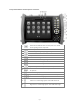
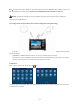
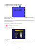
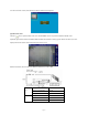
Top interface
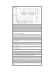
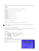
Bottom interface
17
Multimeter inputs (Optional)
18
Charging indicator
19
RS485/RS232 data transmission indicator
20
RS485/RS232 receive indicator
21
Battery life indicator
22
Fiber cable testing visible red laser source. Emits dangerous light!!! Do not
look at directly. (Optional)
23
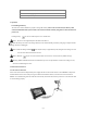
12VDC 2A power output for testing cameras or other devices
24
SDI input (Optional)
25
Analog video signal input(BNC interface)
26
Analog video signal output(BNC interface)or cable tracer interface
connection.
27
Optical power meter input (Optional)
28
RS485 Interface: RS485 bi-directional connector for a PTZ or other RS485
communication
29
RS232 Interface: RS232 bi-directional connector for a PTZ or other RS232
communication
30
LED “flashlight” lamp
31
TDR cable input (Optional)
32
HDMI output connector (mirrors unit display image)
33
Micro SD card slot (comes with 4GB, supports up to 16GB)
34
UTP cable port: UTP cable tester port or Cable tracer port
35
Audio output and earphone interface (3.5mm)
36
Audio input (3.5mm)
37
PSE power sourcing equipment. Tests PoE voltage.
38
PoE power supply output or LAN test port (Use to test PoE or non-PoE IP
camera)