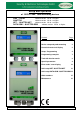
Setup and Operation of ’SECU-TANK’ tank monitoring devices ONE / RELAY software version V6.0x or higher QUATTRO software version V6.0x or higher NET / QUATTRO NET software version V6.0x or higher DATA GSM / QUATTRO GSM software version V6.0x or higher Content: Page: Device setup and probe mounting 2 Control elements and display 2 Setup / Programming 4 Programming examples 7 Tank with interior mantle 8 Special parameters 9 Error codes / error display 12 Add. setup NET / QUATTRO NET 13 Add.
Device setup and probe mounting Concerning installation and mounting as well as regulations and operation please check the corresponding device documentation. The initial setup is to be performed after completed mounting. The monitoring devices of the SECU TANK-series are to be used for tank content measurement and if applicable for data forwarding or transmission. For programming of the device the subsequent description is to be followed.
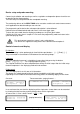
Choose the displaying mode: In menu step ‘6. View‘ the favored displaying mode has to be selected. Therefore the menu steps 1 to 5b need to be setup. The upper display line shows the name of the tank/fluid. The tank can be renamed in ’18. Language+Name‘. The lower display line can show the fillable free space in the tank and /or the inventory volume in percent up to the filling limiter or the present cm level. Setup: View tanks ‘Single/Details’ In line 2: Fillable space (-) L + Vol.
Setup / Programming To enter the setup menu press the [Enter] pushbutton. The setup menu consists of the basic menu items 1 to 7. The specific menu items 9 to 24 contain extra adjustments. The device types QUATTRO, QUATTRO NET and QUATTRO GSM are compatible to link and display more than one measuring probe. In this case the number of the tanks is requested before the menu is entered. Press [Enter] one time and then select the number of the tank by pressing [ + ] / [ - ].
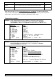
3. Tank shape Selection of the shape of the holding tank: Alternatively just 1 special tank geometry can be setup by a ‘Bearing chart’ for liter conversion. Linear Default: Linear tank. Rectangular tank; vertical cylinder; steel cellar tank. Cylindric horiz ( < 50m3 ) Cylindric tank, up to 45m³. Horizontal lying steel tank. Typical tank shape for outdoor and buried tanks. Diameter <= 250cm Ball-shaped Spherical tank. Ball-shaped subgrounded tank; common subgrounded plastic tanks (GRP).
Input function: Menu main item Description 4. Tank volume Enter the tank volume by [+] [-]. ( 100% value) Preadjustment is 0 L . The value must be entered. In case of tanks > 1.000.000 units see menu item 12 too. Attention: If a bearing chart is available, please utilize total value. For a buried tank of ~100 m3 it may be e.g. 100600 liters. all 5. Tank height Enter the interior height of the tank in cm: e.g. 249.
In case of RELAY also setup the switching points for relay 2. RELAY 8. Exit Press [Enter] to leave the setup mode (parameter input). all Menu items 9 – 24 Steps 9 – 24 contain special settings. all After setting up step 1 to 7 the standard programming is completed. The device automatically returns to the usual displaying mode by confirming the ‘Exit’ step. The display shows the present tank content.
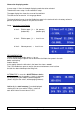
Example 3 Fountain, 7.50 m max. water level from ground (present level 4.20 m) Probe TDS-6131 (measuring range 0-1000 mbar), display in m of water level. Device RELAY. Relay 1 has to protect the pump against running dry (switch off): Menu item Input 1. Measuring probe 2. Liquid 3. Tank shape 4. Tank volume 1000 mbar Water Linear (Volume) Alternatively max. level 7.50 m 7500 [ ] (enter by +/- ) (Max.level) 750.0 cm (enter by +/- ) 99%=7.
Special parameters Additional input functions: Description Menu items 1 to 7 The menu items 1 to 7 contain the basic setup of the devices. Some special settings like language or network parameters or others have to be set up via menu items 9 to 24. all 9. Offset probe Sub-menu a. ‘Offset calibration‘ (electrical zero point) b. ‘Probe bottom gap’ (position over ground) c. ‘Bottom dead stock’ (shall not be displayed) - ESC Exit this sub-menu.
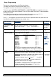
15. Network or 15. Modem 16. Sort tanks / Clear tank 17. Input/Output P. 10 NET, QUATTRO NET : - DHCP . . . Sub-menu for network parameter setup like IP addresses, message destination and communication test. Please coordinate these settings with your network admin. See additional documentation ’network device connection’. DATA, QUATTRO GSM: - Send SMS . . . A test SMS will be sent to the mobile number set by #T command. See additional documentation ‘Messages, Commands a. Parameters’. - PIN . . . .
Additional input functions: 18. Language Description Language : ‘German’ / ‘English’ / ‘French‘ / ‘ESC’, ... use + / - / Enter Names : ... 19. Exit For which device Name and characters are overwriteable. Characters changeable by + / - / Enter - Tank 1: abcabc - Tank n: xyzxyz - Alarm name: Alarm A Press [Enter] for returning to the displaying mode. all all all 20. LCD display By factory setup the contrast of the LCD display is a hexadecimal value of e.g. 24 . Contrast: xx all 21.
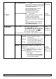
Error codes / error display Message Meaning Error E 1 Invalid input value. Error E 2 Error E 3 Measuring value of the probe is too small ! If current is less than 3.7 mA => Probe error. Measuring value is too high for zero-point calibration or offset calibration. The probe must not be plunged ! A probe current higher than 4.3 mA indicates a defective probe. Error E 4 Call step ‘9.Offset probe’ and perform the calibration once. Then retry settings.
For device type NET / QUATTRO NET: Info/Error-Messages at network communication Error N 1 No network communication. A problem at the internal network module. The device automatically executes a ’Reset’ for the internal network module and retrys initial communications. Try disconnection of network plug, wait… and remount the network plug. Error N 2 Error at the network communication. Check the connections at the device and at the network router... Check parameter setup at menu item ‘15.Network’...
For device type DATA GSM / QUATTRO GSM: Error messages of GSM module / SIM card / Mobile network Error M 0 GSM modem is inactive. Entering PIN => 0000 deactivates the modem completely. Error M 1 Internal communication error. The device automatically executes an internal RESET and retries communication with the internal modem again. Error M 2 SIM card is not inserted or is not readable or is defective. Please check the SIM card in a mobile phone. Error M 3 PUK code must be entered.
Order numbers: Device sets without level measuring probe: Item No.
Maintenance: It is recommended to check once a year if the displayed values are correct. Two practical check options are: - Lift the probe above the liquid level. Then check if ~ 0 L is displayed. - Check the cm value displayed in Step ‘10.Trim height’ (without trimming!). In case of deviation it is recommended to recalibrate the measuring probe via menu step 9 or 10. If the problem cannot be fixed the level probe might be defective. In this case please directly contact Tecson.