MR-2300 SERIES LCD Fire Alarm Control Panel USER GUIDE Revision A Document #: LT-954SEC WARNING: This manual contains information on limitations regarding product use and function and information on the limitations as to liability of the manufacturer. The entire manual should be read carefully.
MR-2300 Series LCD Version User Guide Contents Introduction .............................................................................................................................. 1 About this Manual ................................................................................................................. 1 Technical Support ................................................................................................................. 1 Main Display .........................................
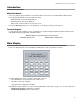
MR-2300 Series LCD Version User Guide Introduction About this Manual This user’s guide provides information on the main indicators and controls of the MR-2300 Fire Alarm Control Panel. Specifically, with this manual you will learn about: • What the LEDs on the main display indicate • What the buttons on the main display do • What certain common LCD screen messages mean Refer to the Glossary on page 11 for an explanation of commonly used terms in this manual.
The Buzzer and LED Indicators The Buzzer and LED Indicators A.C. ON ALARM SUPV TRBL CPU FAIL Buzzer The buzzer sounds if there is a fire alarm, a supervisory alarm, or a trouble in the fire alarm system. It turns off if the condition causing the buzzer to sound goes away or the Buzzer Silence button is pressed. AC On LED The green AC On LED illuminates steadily as long as the main power is above minimum level.
MR-2300 Series LCD Version User Guide Main Display Buttons System Reset Button The System Reset button resets the fire alarm control panel and all circuits. SYSTEM RESET Signal Silence Button SIGNAL SILENCE Pressing the Signal Silence button when the panel is in alarm deactivates any silenceable signal devices in the fire alarm system. Non-silenceable signal devices are unaffected. If you press the Signal Silence button a second time, or if there is a subsequent alarm, the signals will re-sound.
Disconnecting/Reconnecting a Circuit (Zone) Disconnecting/Reconnecting a Circuit (Zone) You can disconnect and reconnect detection and signal circuits (zones) from the panel using the bypass options in the menu. To select the bypass options, you must be in the Command Menu. To enter the Command Menu, press MENU . Step 1: Enter your passcode 1. Enter the passcode Enter your passcode. 2. Press ENTER to continue. Step 2: Select the Bypass Menu - Bypass Det Zone - 1.
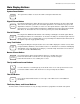
MR-2300 Series LCD Version User Guide Understanding On-screen Messages The LCD screen of the fire alarm control panel displays messages regarding system events. System events display on the screen in a queue. Events in this queue are listed on the screen in order of priority: alarms are of highest priority, followed by supervisory, trouble, and monitor conditions.
Understanding On-screen Messages Common Messages Common system messages are outlined below. AC Power Fail The “AC Power Fail” message indicates that the power has dropped below the minimum level and the system is running on backup battery power. The trouble is removed when the power returns to the normal value.
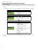
MR-2300 Series LCD Version User Guide Ground Fault The “Ground Fault” message indicates that T ro u b le co d e T ro u b le T yp e Ground Fault Active "I N F O " K e y 1/ 1 T ro u b le In fo Trb:0x03 Info:0x0001 00:07 SAT 2000-01-01 T IM E EVEN T 01 of 01 DATE RAU num mismatch The “RAU num mismatch” message can display for one of two reasons: either the main panel and annunciator failed to communicate with each other or an unconfigured remote annunciator is communicating with the main panel.
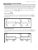
Understanding On-screen Messages 4Wire Pwr. Supply The “4Wire Pwr. Supply” message indicates that the panel has detected a short on a four-wire smoke supply the power is cut off and a trouble message is generated. Press the SYSTEM RESET key to restore the power the system. If the short is removed, the panel will return to normal; otherwise the trouble message will stay. T ro u b le c o d e T ro u b le T yp e 4Wire Pwr.
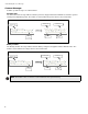
MR-2300 Series LCD Version User Guide City tie Polarity reversal - SPR-200/ Relay module The “CtyTie/MR2312 missin” message below indicates that the city tie, polarity reversal module or the relay module is not plugged in.
Glossary Glossary Alarm Condition Occurs when devices such as detectors, pull stations, or sprinklers are activated. In a single stage system, this condition will activate all signalling devices throughout the building. In a two stage system, this condition will activate an alert signal and the General Alarm timer. Circuits Refers to an actual electrical interface and can be classified as initiating (detection), indicating (signal), or relay.
MR-2300 Series LCD Version User Guide Trouble Flash Rate 20 flashes per minute is the rate at which an LED will flash to indicate a trouble condition. Walk Test A test performed by a technician to ensure that each detection device is connected to the panel and working properly. Zones A fire alarm protected area that consists of at least one circuit. The terms “circuit” and “zone” are often used interchangeably in the fire alarm industry.
© 2006 Secutron, Inc. No part of this publication may be reproduced, transmitted, transcribed, stored in a retrieval system, or translated into any language or computer language, in any form by any means electronic, magnetic, optical, chemical, manual, or otherwise without the prior consent of Secutron. Canada 25 Interchange Way Vaughan, ON L4K 5W3 Tel: (888) SECUTRON (888) 732-8876 Fax: (905) 660-4113 U.S.