
Data Sheet
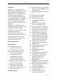
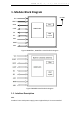
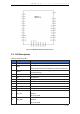
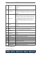
Table Of Contents

W M B T 0 1 ( - s , - s c ) D a t a s h e e t
9
/
36
Figure 4 WMBT01 Module PIN Definition
3.1. PIN Descriptions
Table 2 PIN Descriptions
PIN
PIN description
Function
1
GND
Power ground.
2
VDD
1.9V to 3.6V power supply, 3.3V recommended. Need
external 10uF and 0.1uF capacitor connected to this pin.
3
BOOT
Pull down when firmware upgrade, pull up or NC when
normal working.
4
NC
No Connect
5
NC
No Connect
6
GPIO7
Configurable GPIO, NC if not used.
7
NC
No Connect
8
NC
No Connect
9
NC
No Connect.
10
GPIO15
Configurable GPIO, NC if not used.
11
I2C_SCL
I2C Clock
GPIO17
NC if not used.
12
I2C_SDA
I2C DATA
GPIO18
NC if not used.