
User's Manual


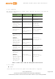

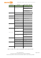

Table Of Contents
- 1. Introduction
- 2. Development Environment
- 2.1. Operating Systems
- 2.2. OpenWrt Introduction
- 2.3. Network Environment
- 2.4. System Configuration
- 2.4.1. Accessing Web UI
- 2.4.2. Accessing System Console
- 2.4.3. Using SSH (Secure Socket Shell)
- 2.4.4. Using Serial to USB Cable
- 2.4.5. Upgrading Firmware
- 2.4.6. Upgrading bootloader
- 2.4.7. Wi-Fi Reset
- 2.4.8. Factory Reset
- 2.4.9. Connecting LinkIt Smart 7688 To a network with Wi-Fi Access Point
- 2.4.10. Open a system console and enter the following commands to change LinkIt Smart 7688 to station mode ( For more information on system console, please see 2.4.1 “Accessing Web UI
- 2.4.11. Viewing System Information from the Web UI
- 2.5. Accessing the USB drive and the SD card

MediaTek LinkIt™ Smart 7688 User Manual
Category Feature
LinkIt Smart 7688
Spec.
Pin numbers
• P22, P23,P24
(Shared with
on-board
flash)
• P25
Max. Speed
25 MHz
SPI Slave
Set count 1 (MT7688AN)
Pin numbers
P28, P29, P30,
P31
Max. Speed
25 MHz
I2S
Set Count
1 (MT7688AN)
Pin numbers
P10, P11, P12,
P13
I2C
Set Count
1
Pin numbers
P20, P21
Speed
120K/400K
UART (Lite)
Set Count
3 (MT7688AN)
Pin numbers
P8, P9, P16, P17,
P18, P19
Max. Speed 115,200 bps
USB Host
Pin Count
1 (MT7688AN)
Pin numbers
P6, P7
Connector type
Micro-AB
Communicatio
n
Wi-Fi
1T1R 802.11 b/g/n
(2.4G)
Ethernet
1-port 10/100 FE
PHY
Pin numbers
P2, P3, P4, P5
User Storage SD Card
Micro SD
SDXC
Table 5 LinkIt Smart 7688 development boards specifications
© 2015, 2016 MediaTek Inc.
Page 10 of 38
This document contains information that is proprietary to MediaTek Inc.
Unauthorized reproduction or disclosure of this information in whole or in part is strictly prohibited.