
Data Sheet


© 2008-2020 Seeed Technology Co., Ltd. All rights reserved. www.seeedstudio.com 15 / 18
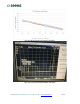
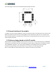
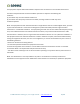
The following figure shows the recommended Layout package dimensions.
Figure 17 PCB layout
5.2 External interface of the module
In addition to several necessary GPIO ports and a set of SPI ports used for internal RF transceiver control, other
GPIOs of the MCU have been derived, including UART (for AT commands), I2C, ADC, etc. For customers who
want to develop software on the MCU of the module, these rich GPIO interfaces are very useful for users who
need to expand peripherals.
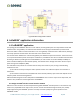
5.3 Reference design based on LoRa-E5 module
LoRa-E5 embeds the global LoRaWAN
®
protocol and AT instruction set. This will make the design of LoRaWAN
®
nodes based on this module very easy. The following is a typical reference design that uses LoRa-E5 to quickly
start a LoRaWAN
®
application. Just connect UART and NRST to the host MCU and send AT commands.
In addition,Pin24 grounding of the module will force the module to enter Boot upgrade mode.
Note: The 28-pin PB0 must be left floating and not allowed to be pulled up or grounded.