User manual/ Technical information User Manual for All-in-One Weather Sensors SenseCAP ONE Series Version: V1. 4 Dates: 2020-4-16 The 1 Page total 50 Page © 2008-2020 Seeed Technology Co., Ltd. All rights reserved. www.seeed.
User manual/ Technical information Tables of Contents Tables of Contents .................................................................................................................................................. 2 1 Product Introduction ..................................................................................................................................... 5 2 Installation ................................................................................................................
User manual/ Technical information 4.2.2 Query Command Format .................................................................................................... 34 4.2.3 Setting Command Format .................................................................................................. 34 4.2.4 Command List ........................................................................................................................ 34 SDI-12 ..........................................................
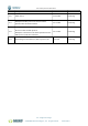
User manual/ Technical information Version Description Date The modifier V1.0 Initial version 02-09-2020 Kevin Yang 09-12-2020 Kevin Yang 24-12-2020 Kevin Yang 12-4-2021 Kevin Yang V1.1 Modify the Modbus protocol section, barometric pressure value calculation method Modify the definition for these 2 symbols “&”, “;” in V1.2 the return values of ASIIC protocol. Modify the command for rain-related parameters in the ASIIC protocol; add Clear command V1.3 Add heating function, PM2.
User manual/ Technical information 1 Product Introduction SenseCAP ONE is a series of all-in-one compact weather sensors, including S900 9-in-1, S700 7in-1, and S500 5-in-1 weather sensors. These weather sensors integrate multiple sensors into this compact device, monitoring up to 9 weather parameters: air temperature, air humidity, atmospheric pressure, light intensity, wind speed, wind direction, precipitation, PM 2.5, and PM 10.
User manual/ Technical information Precipitation 0~200mm/h PM2.5 0~1000µg/𝑚3 PM10 0~1000µg/𝑚3 ±5% 0.2mm/0. 02mm ±10%@100~1000µg/𝑚3 ±10µg/𝑚3@0~100µg/𝑚3 ±15%@100~1000µg/𝑚3 ±15µg/𝑚3@0~100µg/𝑚3 1µg/𝑚3 1µg/𝑚3 The 6 Page total 50 Page © 2008-2020 Seeed Technology Co., Ltd. All rights reserved. www.seeed.
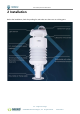
User manual/ Technical information 2 Installation Before the installation, check the packing list and make sure there are no missing parts. The 7 Page total 50 Page © 2008-2020 Seeed Technology Co., Ltd. All rights reserved. www.seeed.
User manual/ Technical information Packing List Number Parts Number 1 SenseCAP ONE All-in-one compact weather sensor 1 M12 8-pin communication cable (default length 3-meter hook-up wire, 2 and there is a waterproof aviation connector type to choose when 1 working with SenseCAP SensorHub datalogger) 3 USB Type-C cable, for configuring devices 1 4 Flange plate (purchased separately) 1 5 Pole adapter sleeve base (purchased separately) 1 6 Pole adapter cross bar (purchased separately) 1 Th
User manual/ Technical information Installation 2.2.1 Device Interface Introduction There are two connectors at the bottom of the device. • USB Type-C interface allows you to connect your computer with a normal USB Type-C cable to the device for configuration. • The main data interface can be connected to the M12 8-pin cable, supporting multiple bus protocols The 9 Page total 50 Page © 2008-2020 Seeed Technology Co., Ltd. All rights reserved. www.seeed.
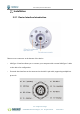
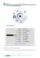
User manual/ Technical information 2.2.2 Connect with USB Cable 2.2.3 M12 Cable The device adopts an M12 8-pin connector, the different colored pins provide power and data communication (as shown in the above diagram). When working with the RS-485, you can connect only 4 wires (not using a heating function), and The 10 Page total 50 © 2008-2020 Seeed Technology Co., Ltd. All rights reserved. www.seeed.
User manual/ Technical information the rest can be individually wrapped with tape to prevent short circuit The holes of the cable and the pins of the device connector must be aligned when the cable is plugged in. Plugin the cable and tighten it clockwise The 11 Page total 50 © 2008-2020 Seeed Technology Co., Ltd. All rights reserved. www.seeed.
User manual/ Technical information When using the device with a heating function, a separate 12V-24V (12V@2A is recommended) power supply is required. Gray wire #5 is connected to the negative of the power supply, and pink wire #6 is connected to the positive pole of the power supply. 2.2.4 Install the device. There are two major installation methods, either mount on a pole with a sleeve or a platform with a flange plate. The 12 Page total 50 © 2008-2020 Seeed Technology Co., Ltd. All rights reserved.
User manual/ Technical information The size of the sleeve is shown below. The 13 Page total 50 © 2008-2020 Seeed Technology Co., Ltd. All rights reserved. www.seeed.
User manual/ Technical information It is recommended that the diameter of the pole should be less than or equal to 75cm. The 14 Page total 50 © 2008-2020 Seeed Technology Co., Ltd. All rights reserved. www.seeed.
User manual/ Technical information The dimension of the flange plate is shown below. The 15 Page total 50 © 2008-2020 Seeed Technology Co., Ltd. All rights reserved. www.seeed.
User manual/ Technical information The 16 Page total 50 © 2008-2020 Seeed Technology Co., Ltd. All rights reserved. www.seeed.
User manual/ Technical information 3 Device's Operating Mode After installation, you can power on the device, configure it and collect data from the device. The device has two operating modes, configuration mode, and working mode. With a USB cable, you can check or configure the device’s parameters, such as device name, version number, and Configuration Mode communication protocol configuration. Product firmware can be upgraded in this mode.
User manual/ Technical information Configure the device via USB port There is a waterproof round cover at the bottom of the device. Turn it counterclockwise to remove this cover, and you can see a USB Type-C connector and a configuration button. Connect the device to your computer with a USB Type-C cable. The computer will automatically install the device driver. After the driver is successfully installed, you can see a serial port in the device's manager.
User manual/ Technical information SenseCAP ONE Configuration Tool SenseCAP ONE Configuration Tool offers a graphical interface for you to configure the device. And you can download the tool from the GitHub link below: https://github.com/Seeed-Solution/SenseCAP-One-Configuration-Tool/releases Select the software for the respective operating system, Windows, macOS, or Linux based on your needs. The next image shows the main interface of the SenseCAP ONE Configuration Tool.
User manual/ Technical information 1. Open the software, click on the pull-down box at the serial port, select the corresponding serial port of the device. 2. Set the Baud rate to 9600. 3. Click connect, if the connection is successful, the sensor data area on the right will show the corresponding measurements. Click Settings to enter the device settings. The 20 Page total 50 © 2008-2020 Seeed Technology Co., Ltd. All rights reserved. www.seeed.
User manual/ Technical information 1. Select the communication protocol. In the example here we choose the RS-485 Modbus RTU. 2. Modify the Modbus address: write the address in the Modbus address, and then click “Write to Device”. The 21 Page total 50 © 2008-2020 Seeed Technology Co., Ltd. All rights reserved. www.seeed.
User manual/ Technical information On the configuration page, you can modify the following: device name, data type, and data upload interval. After any modification, you will need to click “Write to Device” for the changes to take effect. In application settings, you can set the cycle for the tool to read sensor data, with the minimum as 2S, and a dot range for the curve. Click “Firmware Update” to update the device firmware. Please contact sales or technical support at (sensecap@seeed.
User manual/ Technical information On the upgrade page, you will need to choose to update the mainboard firmware or the driver board firmware. Select the firmware file at your local repository, click “Update Now”. If there is an unexpected power break during the update process, the update won’t be executed. You will need to go through the same process to update the firmware. The 23 Page total 50 © 2008-2020 Seeed Technology Co., Ltd. All rights reserved. www.seeed.
User manual/ Technical information Serial debug tool The communication settings are as follows: Select the serial port You can find port information in your computer's device manager Baud rate 9600bps, 8 data bits, 1 stop bits, none parity, none flow control. In the Serial Debug Assistant, select the corresponding COM port. Check the "click Enter to start a new line" check box. Set the baud rate to 9,600. Send ? in the send area.
User manual/ Technical information configuration is successful. If not, please check the COM port and the baud rate. Please check the detailed ASIIC command in the next chapter. The 25 Page total 50 © 2008-2020 Seeed Technology Co., Ltd. All rights reserved. www.seeed.
User manual/ Technical information 4 Communication Protocols The device supports the following communication protocols: The Modbus protocol is a common language applied to electronic devices. With this protocol, devices can communicate within their network. It has become a universal industry standard, widely used in data loggers, sensor equipment, and so on. Based on Modbus-RTU this protocol, devices produced by different vendors can communicate with each other for system integration.
User manual/ Technical information Modbus-RTU Protocol To start Modbus-RTU communication, the M12 data cable of the device needs to be connected to the RS-485 port of one Data Logger, which powers up the device at a voltage of 12V-24V. The following image is a diagram of the wiring: Protocol communication parameters Data Format One start bit, 8 Data bits, None parity, one Stop bits. Baud Rate 9600bps (default), which can be modified by configuration. Default Device Address 0x01 4.1.
User manual/ Technical information The message response from the slave Slave address Function code Number of registers First Register data Second register data ... CRC check 1 byte 1 byte 1 byte 2 bytes 2 bytes ... 2 bytes AA 0x04 MM VV0 VV1 ... CCCC Address 0-247 0x04 big endian big endian big endian ... little-endian Read and write the holding register.
User manual/ Technical information speed 0x0014 0x0016 0x0018 0x001A 0x1000 Accumulated rainfall Accumulated rainfall duration Rain intensity Maximum rainfall intensity 0~80000 2 R 0~2000000 2 R 0-80000 2 R 0-80000 2 R 1 R/W Device address The default address is 1 Can be set to 1 - 247 The default is 96, which means 9600.
User manual/ Technical information Configuration connection parameters: Baud rate 9600bps, 8 Data bits, None Parity, 1 Stop bits. Read the air temperature register 0x0000 to 0x0001, click Setup, and select Read/Write Definition The 30 Page total 50 © 2008-2020 Seeed Technology Co., Ltd. All rights reserved. www.seeed.
User manual/ Technical information Set the default slave ID to 1, function code 04, starting address 0, quantity 2 Now the computer reads the sensor data every 1 second, and the measurement (line 0 and line 1) is shown in below picture, after dividing the measurement by 1000, it is the true temperature value, 28300/1000 = 28.3 °C On the right, you can check the raw sent and received data packages. When the temperature is positive: 1. Host sends 01 04 00 00 00 02 71 CB 2.
User manual/ Technical information 28.3 °C When the temperature is negative: The temperature needs to be obtained through a complement calculation. 1. Host sends 01 04 00 00 00 02 71 CB 2. Slave responses 01 04 04 FF FF FC 18 D6 41 3. Returned temperature data FFFFFC18H (Hex complement). 4. The original code is - (FF FF FC 18-1 = FF FF FC 17) = 80 00 03 E8(Hex) = -1000 (Decimal). 5. Then the temperature measurement is -1000/1000 = -1° The 32 Page total 50 © 2008-2020 Seeed Technology Co., Ltd.
User manual/ Technical information ASCII Protocol 4.2.1 Command definition A Device address, 0 by default XA Starter, fixed value ; The separator used to distinguish multiple commands ...
User manual/ Technical information 4.2.2 Query Command Format Commands come in two formats: 1. A command without = refers to the basic query method. Example: ? indicates query the device’s address 2. A command with = refers to a query with an argument Example: 0XA;BD=? indicates query the device’s baud rate 4.2.3 Setting Command Format Set a specified parameter, such as setting a baud rate. Example: 0XA;BD=96 indicates query the device’s baud rate 4.2.
User manual/ Technical information Response 0XA; BD=96 Description The baud rate for device 0 is 9,600 Send 0XA; BD=[bd] Response 0XA; BD=[bd] Return the Baud rate of device 0 is [bd], it could be 96 for 9600; 192 for 19200, 384 for 38400; Setting Description 576 for 57600; and 1152 for 115200.
User manual/ Technical information 384 for 38400, 576 for 57600, and 1152 for 115200.
User manual/ Technical information Description Send 0XA;CC=C Response 0XA;CC=C Description Tilt Detect Send Response Query Description Setting Enable Geomagnetic compensation,it will start the 30s compensation process, during this time, the device should be placed horizontally, and rotate evenly along the Z-axis for 1-2 rounds.
User manual/ Technical information Group Name Measurement Name Unit Contains all combinations of measurement parameters G0 AT Air temperature ℃ (default), ℉ AH Air humidity %RH AP Barometric pressure Pa (default), hPa, bar, mmHg, inHg LX Light intensity Lux DN Minimum wind direction deg Dm Maximum wind direction deg DA Average wind direction deg SN Minimum wind speed m/s (default), km/h, mph, knots SM Maximum wind speed m/s (default), km/h, mph, knots SA Average wind speed
User manual/ Technical information Query Set up Send 0XA; UP=? Response 0XA; UP=P Description The unit is Pa. Send 0XA; UP=H Response 0XA; UP=H Set the unit to hPa. Description P = Pa, H = hPa, B = bar, M = mmHg, I=inHg Wind Speed & Direction Data Update Interval Query Set up Send 0XA; IW=? Response 0XA; IW=1 Description The default data updates every 1 second.
User manual/ Technical information Query Setting Send 0XA;IR=? Response 0XA;IR=10 Description The default rain data update interval is 10 seconds. Send 0XA;IR=60 Response 0XA;IR=60 Set the data update interval to 60seconds. Description The interval range is 10 to 3600 seconds.
User manual/ Technical information The default rainfall duration overflow value is 2,000,000, the unit is second. Description This overflow value will only take effect when the CR rainfall counter reset mode is L overflow reset. Setting Send 0XA; DL=3600 Response 0XA; DL=3600 Set the rainfall duration overflow value to 3600 seconds. Description It ranges between 100 – 2000000 seconds.
User manual/ Technical information SDI-12 SDI-12 communication adopts three wires, two of which are sensor power supply wires and the other is SDI-12 signal wire. Each sensor on the SDI-12 bus has a unique address, which can be set to ‘0’, ‘1’ ~ ‘9’, ‘A’ ~ ‘Z’, ‘A’ ~ ‘Z’. The SDI-12 address of the SenseCAP ONE defaults to ‘0’. The instructions supported by this sensor are shown in the next chapter, where each instruction conforms to the SDI-12 v1.4. The sensor is powered by a DC power supply of 3.6~16V.
User manual/ Technical information Response 014SenseCAPONE3.01019906922104001 Response the device information accccccccmmmvvvxxxxxxxxxxxxxxxx Description Modify device a Device address: 0 14 SDI-12 protocol version :v1.4 cccccccc Product:SenseCAP mmm Device series:ONE vvv Software version:3.0 xxxxxxxxxxxxxxxx Device serial number:1019906922104001 0Ab! address Send Response Description 0A1! 1 Device address 0 is changed to 1. The address range is 0-9、A-Z、a-z.
User manual/ Technical information 0M4!...0M8!: reserved. After using this command, the sensor will enter a sleep mode after the measurement to save power consumption. After using "continuous measurement command 0R0!...0R9!", it will exit the low power consumption state. For the definition of reply, please refer to "Start measurement command 0M!" Read 0D0!...0D9! measurement value Send Response 0D0! 0+27.65+65.81+100000+5000 This command is used to obtain a set of measurement data in the sensor.
User manual/ Technical information exit the low-power working state. Start Measurement aMC!,aMC1!...aMC9!,aRC0!...aRC9! with CRC Send Response 0RC0! 0+26.52+67.73+100280+35JKy To enhance the error detection capability of the SDI-12 protocol, "start measurement command 0M!", "extended measurement command 0M1!..0M9!" and "continuous Description measurement command 0R0!...0R9!" can add 16-bit cyclic redundancy check.
User manual/ Technical information The communication settings: Format 1 start bits, 7 data bits, Even parity, 1 stop bits Baud rate 1200bps Device address 0x00 Connect the green wire (GND Data) and yellow wire (SDI-12 Data) to the USB to SDI-12 debugger. And connect the red wire (Vin+ power positive) and brown wire (Vin- power ground) to the 12V power supply. Download the serial port debugging assistant: https://github.com/Neutree/COMTool,and then open the serial port debugging tool.
User manual/ Technical information Start Measurement Read air temperature, air humidity, barometric pressure, light intensity Send the "start measurement command 0M!", the sensor first responds with "00024", which means that the "0M!" command takes 2 seconds to measure and returns 4 measured values. After 2 seconds, the sensor responds with its own address "0", indicating that the measurement has been completed.
User manual/ Technical information measurement, which are air temperature +27.01℃, air humidity 64.74%, barometric pressure 100720Pa, and light intensity 10Lux. Use extended measurement command 0M1! to read minimum wind direction, maximum wind direction, average wind direction, minimum wind speed, maximum wind speed, average wind speed. The device responds with "00056", which means that the "0M1!" command takes 5 seconds to measure and returns 6 measured values.
User manual/ Technical information Then send " Read measurement value command 0D0!" to get the 6 measured values of this measurement, which are minimum wind direction 345.9 degrees, maximum wind direction 347.5 degrees, average wind direction 346.3 degrees, minimum wind speed 2.8m/s, and maximum wind speed 2.8m. /s, average wind speed 2.8m/s. Then send “continuous measurement command 0R2!, the device returns 4 measured values: cumulative rainfall 1.
User manual/ Technical information 6 Error code Modbus error code Error code Description Response instance 0x01 Device do not response 01 84 01 82 C0 0x04 Sensor probe exception 01 84 04 42 C3 Error code Description Response instance 0 Command do not exist 0XA;...