
Data Sheet


100
Atmel | SMART SAM D21 [DATASHEET]
Atmel-42181G–SAM-D21_Datasheet–09/2015
When a generic clock generator has been selected, the generic clock is enabled by writing a one to the Clock Enable bit
in CLKCTRL (CLKCTRL.CLKEN). The CLKCTRL.CLKEN bit must be synchronized to the generic clock domain.
CLKCTRL.CLKEN will continue to read as its previous state until the synchronization is complete.
14.6.3.2 Disabling a Generic Clock
A generic clock is disabled by writing a zero to CLKCTRL.CLKEN. The SYNCBUSY bit will be cleared when this write-
synchronization is complete. CLKCTRL.CLKEN will continue to read as its previous state until the synchronization is
complete. When the generic clock is disabled, the generic clock is clock gated.
14.6.3.3 Selecting a Clock Source for the Generic Clock
When changing a generic clock source by writing to CLKCTRL.GEN, the generic clock must be disabled before being re-
enabled with the new clock source setting. This prevents glitches during the transition:
1. Write a zero to CLKCTRL.CLKEN
2. Wait until CLKCTRL.CLKEN reads as zero
3. Change the source of the generic clock by writing CLKCTRL.GEN
4. Re-enable the generic clock by writing a one to CLKCTRL.CLKEN
14.6.3.4 Configuration Lock
The generic clock configuration is locked for further write accesses by writing the Write Lock bit (WRTLOCK) in the
CLKCTRL register. All writes to the CLKCTRL register will be ignored. It can only be unlocked by a power reset.
The generic clock generator sources of a locked generic clock are also locked. The corresponding GENCTRL and
GENDIV are locked, and can be unlocked only by a power reset.
There is one exception concerning the GCLKGEN[0]. As it is used as GCLK_MAIN, it can not be locked. It is reset by any
reset to startup with a known configuration.
The SWRST can not unlock the registers.
14.6.4 Additional Features
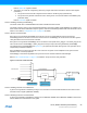
14.6.4.1 Indirect Access
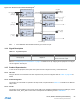
The Generic Clock Generator Control and Division registers (GENCTRL and GENDIV) and the Generic Clock Control
register (CLKCTRL) are indirectly addressed as shown in Figure 14-5.
Figure 14-5. GCLK Indirect Access
Writing these registers is done by setting the corresponding ID bit group.
To read a register, the user must write the ID of the channel, i, in the corresponding register. The value of the register for
the corresponding ID is available in the user interface by a read access.
GENCTR
L
G
ENDIV
C
LK
C
TR
L
G
EN
C
TRL.ID=
i
G
ENDIV.ID=i
CLKCTRL.ID=
j
U
ser Interface
GENCTR
L
G
ENDIV
G
eneric
C
lock
G
enerator [i
]
C
LK
C
TR
L
G
eneric Clock[
j
]