
Data Sheet


161
Atmel | SMART SAM D21 [DATASHEET]
Atmel-42181G–SAM-D21_Datasheet–09/2015
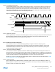
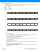
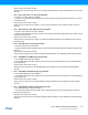
16.6.8.6 Loop Divider Ratio updates
The FDPLL96M supports on-the-fly update of the DPLLRATIO register, so it is allowed to modify the loop divider ratio
and the loop divider ratio fractional part when the FDPLL96M is enabled. At that time, the DPLLSTATUS.LOCK bit is
cleared and set again by hardware when the output frequency reached a stable state. The DPLL Lock Fail bit in the
Interrupt Flag Status and Clear register (INTFLAG.DPLLLCK) is set when a falling edge has been detected. The flag is
cleared when the software write a one to the interrupt flag bit location.
Figure 16-6. RATIOCTRL Register Update Operation
16.6.8.7 Digital Filter Selection
The PLL digital filter (PI controller) is automatically adjusted in order to provide a good compromise between stability and
jitter. Nevertheless a software operation can override the filter setting using the DPLLCTRLB.FILTER field. The
DPLLCTRLB.LPEN field can be use to bypass the TDC module.
16.6.9 3.3V Brown-Out Detector Operation
The 3.3V BOD monitors the 3.3V VDDANA supply (BOD33). It supports continuous or sampling modes.
The threshold value action (reset the device or generate an interrupt), the Hysteresis configuration, as well as the
enable/disable settings are loaded from Flash User Calibration at startup, and can be overridden by writing to the
corresponding BOD33 register bit groups.
16.6.9.1 3.3V Brown-Out Detector (BOD33)
The 3.3V Brown-Out Detector (BOD33) monitors the VDDANA supply and compares the voltage with the brown-out
threshold level set in the BOD33 Level bit group (BOD33.LEVEL) in the BOD33 register. The BOD33 can generate either
an interrupt or a reset when VDDANA crosses below the brown-out threshold level. The BOD33 detection status can be
read from the BOD33 Detection bit (PCLKSR.BOD33DET) in the Power and Clocks Status register.
At startup or at power-on reset (POR), the BOD33 register values are loaded from the Flash User Row. Refer to “NVM
User Row Mapping” on page 30 for more details.
16.6.9.2 Continuous Mode
When the BOD33 Mode bit (BOD33.MODE) in the BOD33 register is written to zero and the BOD33 is enabled, the
BOD33 operates in continuous mode. In this mode, the BOD33 is continuously monitoring the VDDANA supply voltage.
Continuous mode is the default mode for BOD33.
CKRx
LDR
LDRFRAC
CK
CLK_FDPLL96M
mult0
mult1
LOCK
LOCKL