
Data Sheet


215
Atmel | SMART SAM D21 [DATASHEET]
Atmel-42181G–SAM-D21_Datasheet–09/2015
WDT time-out period will be started each time the WDT is cleared by writing 0xA5 to the Clear register (CLEAR). Writing
any value other than 0xA5 to CLEAR will issue an immediate system reset.
By default, WDT issues a system reset upon a time-out, and the early warning interrupt is disabled. If an early warning
interrupt is required, the Early Warning Interrupt Enable bit in the Interrupt Enable register (INTENSET.EW) must be
enabled. Writing a one to the Early Warning Interrupt bit in the Interrupt Enable Set register (INTENSET.EW) enables the
interrupt, and writing a one to the Early Warning Interrupt bit in the Interrupt Enable Clear register (INTENCLR.EW)
disables the interrupt. If the Early Warning Interrupt is enabled, an interrupt is generated prior to a watchdog time-out
condition. In normal mode, the Early Warning Offset bits in the Early Warning Interrupt Control register
(EWCTRL.EWOFFSET) define the time where the early warning interrupt occurs. The normal-mode operation is
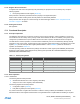
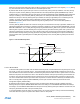
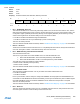
illustrated in Figure 17-2.
The Early Warning Offset bits define the number of GCLK_WDT clocks before the interrupt is generated, relative to the
start of the watchdog time-out period. For example, if the WDT is operating in normal mode with CONFIG.PER = 0x2 and
EWCTRL.EWOFFSET = 0x1, the Early Warning interrupt is generated 16 GCLK_WDT clock cycles from the start of the
watchdog time-out period, and the watchdog time-out system reset is generated 32 GCLK_WDT clock cycles from the
start of the watchdog time-out period. The user must take caution when programming the Early Warning Offset bits. If
these bits define an Early Warning interrupt generation time greater than the watchdog time-out period, the watchdog
time-out system reset is generated prior to the Early Warning interrupt. Thus, the Early Warning interrupt will never be
generated.
Figure 17-2. Normal-Mode Operation
17.6.2.5 Window Mode
In window-mode operation, the WDT uses two different time-out periods, a closed window time-out period (TO
WDTW) and
the normal, or open, time-out period (TO
WDT). The closed window time-out period defines a duration from 8ms to 16s
where the WDT cannot be reset. If the WDT is cleared during this period, the WDT will issue a system reset. The normal
WDT time-out period, which is also from 8ms to 16s, defines the duration of the open period during which the WDT can
be cleared. The open period will always follow the closed period, and so the total duration of the time-out period is the
sum of the closed window and the open window time-out periods. The closed window is defined by the Window Period
bits in the Configuration register (CONFIG.WINDOW), and the open window is defined by the Period bits in the
Configuration register (CONFIG.PER).
By default, the WDT issues a system reset upon a time-out and the Early Warning interrupt is disabled. If an Early
Warning interrupt is required, INTENCLR/SET.EW must be set. Writing a one to INTENSET.EW enables the interrupt,
and writing a one to INTENCLR.EW disables the interrupt. If the Early Warning interrupt is enabled in window mode, the
interrupt is generated at the start of the open window period.
In a typical application where the system is in sleep mode, it can use this interrupt to wake up and clear the Watchdog
Timer, after which the system can perform other tasks or return to sleep mode.
t [ms]
WDT Count
510
15 20 25 30
35
PER[3:0]=1
Timely WDT Clear
TO
WDT
WDT Timeout
System Reset
EWOFFSET[3:0]=0
Early Warning Interrupt