
Data Sheet


230
Atmel | SMART SAM D21 [DATASHEET]
Atmel-42181G–SAM-D21_Datasheet–09/2015
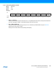
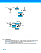
Figure 18-2. RTC Block Diagram (Mode 1 — 16-Bit Counter)
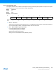
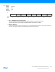
Figure 18-3. RTC Block Diagram (Mode 2 — Clock/Calendar)
18.4 Signal Description
Not applicable.
18.5 Product Dependencies
In order to use this peripheral, other parts of the system must be configured correctly, as described below.
18.5.1 I/O Lines
Not applicable.
18.5.2 Power Management
The RTC can continue to operate in any sleep mode. The RTC interrupts can be used to wake up the device from sleep
modes. The events can trigger other operations in the system without exiting sleep modes. Refer to “PM – Power
Manager” on page 117 for details on the different sleep modes.
The RTC will be reset only at power-on (POR) or by writing a one to the Software Reset bit in the Control register
(CTRL.SWRST).
10-bit
Prescaler
GCLK_RTC
COUNT
PER
Overflow
0
COMPn
Compare n
CLK_RTC_CNT
16
Periodic
Events
16
16
=
=
CLOCK
ALARMn
=
Alarm n
Overflow
0
MATCHCLR
10-bit
Prescaler
GCLK_RTC CLK_RTC_CNT
32
Periodic
Events
32
MASKn
Y/M/D H:M:S
Y/M/D H:M:S