
Data Sheet


361
Atmel | SMART SAM D21 [DATASHEET]
Atmel-42181G–SAM-D21_Datasheet–09/2015
21.6.6 NVM User Configuration
The NVM user configuration resides in the auxiliary space. See “Physical Memory Map” on page 29 for calibration and
auxiliary space address mapping.
The bootloader resides in the main array starting at offset zero. The allocated boot loader section is protected against
write.
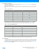
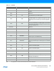
Table 21-2. Boot Loader Size
The EEPROM bits indicates the Flash size reserved for EEPROM emulation according to the Table 21-3. EEPROM
resides in the upper rows of the NVM main address space and are writable, regardless of the region lock status.
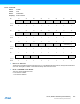
Note: 1. the actual size of the EEPROM depends on the emulation software. For more information see Application Note AT03265
21.6.7 Security Bit
The security bit allows the entire chip to be locked from external access for code security. The security bit can be written
by a dedicated command, Set Security Bit (SSB). Once set, the only way to clear the security bit is through a debugger
Chip Erase command. After issuing the SSB command, the PROGE error bit can be checked. Refer to “DSU – Device
Service Unit” on page 50 for details.
BOOTPROT [2:0] Rows Protected by BOOTPROT Boot Loader Size in Bytes
7 None 0
6 2 512
5 4 1024
4 8 2048
3 16 4096
2 32 8192
1 64 16384
0 128 32768
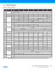
Table 21-3. Flash size for EEPROM emulation
EEPROM[2:0] Rows Allocated to EEPROM EEPROM Size in Bytes for EEPROM emulation
(1)
7 None 0
6 1 256
5 2 512
4 4 1024
3 8 2048
2 16 4096
1 32 8192
0 64 16384