
Data Sheet

443
Atmel | SMART SAM D21 [DATASHEET]
Atmel-42181G–SAM-D21_Datasheet–09/2015
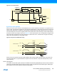
25.5.9 Analog Connections
Not applicable.
25.6 Functional Description
25.6.1 Principle of Operation
The USART uses three communication lines for data transfer:
z RxD for receiving
z TxD for transmitting
z XCK for the transmission clock in synchronous operation
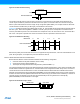
USART data transfer is frame based, where a serial frame consists of:
z 1 start bit
z 5, 6, 7, 8 or 9 data bits
z MSB or LSB first
z No, even or odd parity bit
z 1 or 2 stop bits
A frame starts with the start bit followed by one character of data bits. If enabled, the parity bit is inserted after the data
bits and before the first stop bit. One frame can be directly followed by a new frame, or the communication line can return
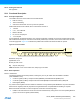
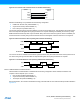
to the idle (high) state. Figure 25-2 illustrates the possible frame formats. Bits inside brackets are optional.
Figure 25-2. Frame Formats
St Start bit; always low
(n) Data bits; 0 to 8
P Parity bit; odd or even
Sp Stop bit; always high
IDLE No transfers on the communication line; always high in this state
25.6.2 Basic Operation
25.6.2.1 Initialization
The following registers are enable-protected, meaning they can only be written when the USART is disabled
(CTRL.ENABLE is zero):
z Control A register (CTRLA), except the Enable (ENABLE) and Software Reset (SWRST) bits
z Control B register (CTRLB), except the Receiver Enable (RXEN) and Transmitter Enable (TXEN) bits
z Baud register (BAUD)
Any writes to these registers when the USART is enabled or is being enabled (CTRL.ENABLE is one) will be discarded.
Writes to these registers) while the peripheral is being disabled will be completed after the disabling is complete.
Before the USART is enabled, it must be configured, as outlined in the following steps:
z USART mode with external or internal clock must be selected first by writing 0x0 or 0x1 to the Operating Mode bit
group in the Control A register (CTRLA.MODE)
1 2 3 4 [5] [6] [7] [8]0St(IDLE) Sp1 [Sp2] (St/IDLE)[P]
Frame