
Data Sheet

654
Atmel | SMART SAM D21 [DATASHEET]
Atmel-42181G–SAM-D21_Datasheet–09/2015
Write-protection is denoted by the Write-Protected property in the register description.
Write-protection does not apply to accesses through an external debugger. Refer to “PAC – Peripheral Access
Controller” on page 41 for details.
30.5.9 Analog Connections
Not applicable.
30.6 Functional Description
30.6.1 Principle of Operation
Each TCC instance has up to four compare/capture channels (CCx).
The following definitions are used throughout the documentation:
In general, the term “timer” is used when the timer/counter clock control is handled by an internal source, and the term
“counter” is used when the clock control is handled externally (e.g. counting external events). When used for compare
operations, the CC channels are referred to as “compare channels.” When used for capture operations, the CC channels
are referred to as “capture channels.”
The counter register (COUNT), period registers with buffer (PER and PERB), and compare and capture registers with
buffers (CCx and CCxB) are 16 or 24-bit registers, depending on each TCC instance. Each buffer register has a buffer
valid (BV) flag that indicates when the buffer contains a new value. During normal operation, the counter value is
continuously compared to the Period (TOP) and to ZERO value to determine whether the counter has reached TOP or
ZERO.
The counter value is also compared to the CCx registers. These comparisons can be used to generate interrupt
requests, request DMA transactions or generate events for the event system. The waveform generator modes use these
comparisons to set the waveform period or pulse width.
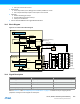
A prescaled generic clock (GCLK_TCCx) and events from the event system can be used to control the counter. The
event system is also used as a source to the input capture.
The recoverable fault module extension enables event controlled waveforms by acting directly on the generated
waveforms from TCC compare channels output. These events can restart, halt the timer/counter period or shorten the
output pulse active time, or disable waveform output as long as the fault condition is present. This can typically be used
for current sensing regulation or zero crossing and demagnetization retriggering.
The MCE0 and MCE1 event sources are shared with the recoverable fault module. Only asynchronous events are used
internally when fault unit extension is enabled. For further details on how to configure asynchronous events routing, refer
to section “EVSYS – Event System” on page 406.
By using digital filtering and/or input blanking, qualification options (as detailed in “Recoverable Faults” on page 671),
recoverable fault sources can be filtered and/or windowed to avoid false triggering, for example from I/O pin glitches.
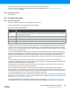
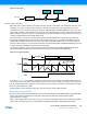
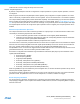
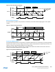
Figure 30-3. Timer/Counter Definitions
Name Description
TOP
The counter reaches TOP when it becomes equal to the highest value in the count sequence. The TOP
value can be equal to the period (PER) or the compare channel A (CCA) register setting. This is selected by
the waveform generator mode.
BOTTOM The counter reaches BOTTOM when it becomes zero
MAX The counter reaches maximum when it becomes all ones
UPDATE The timer/counter signals an update when it reaches BOTTOM or TOP, depending on the direction settings.