
Data Sheet


750
Atmel | SMART SAM D21 [DATASHEET]
Atmel-42181G–SAM-D21_Datasheet–09/2015
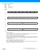
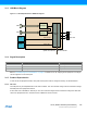
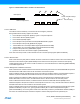
Figure 31-3. Multi-Packet Feature - Reduction of CPU Overhead
31.6.2.4 USB Reset
The USB bus reset is initiated by a connected host and managed by hardware.
During USB reset the following registers are cleared:
z Device Endpoint Configuration (EPCFG) register - except for Endpoint 0
z Device Frame Number (FNUM) register
z Device Address (DADD) register
z Device Endpoint Interrupt Enable Clear/Set (EPINTENCLR/SET) register
z Device Endpoint Interrupt Flag (EPINTFLAG) register
z Transmit Stall 0 bit in the Endpoint Status register (EPSTATUS.STALLRQ0)
z Transmit Stall 1 bit in the Endpoint Status register (EPSTATUS.STALLRQ1)
z Endpoint Interrupt Summary (EPINTSMRY) register
z Upstream resume bit in the Control B register (CTRLB.UPRSM)
At the end of the reset process, the End of Reset bit is set in the Interrupt Flag register (INTFLAG.EORST).
31.6.2.5 Start-of-Frame
When a Start-of-Frame (SOF) token is detected, the frame number from the token is stored in the Frame Number field in
the Device Frame Number register (FNUM.FNUM) and the Start-of-Frame interrupt bit in the Device Interrupt Flag
register (INTFLAG.SOF) is set. If there is a CRC or bit-stuff error, the Frame Number Error status flag (FNUM.FNCERR)
in the FNUM register is set.
31.6.2.6 Management of SETUP Transactions
When a SETUP token is detected and the device address of the token packet does not match DADD.DADD the packet is
discarded and the USB module returns to idle and waits for the next token packet.
When the address matches, the USB module checks if the endpoint is enabled in EPCFG. If the addressed endpoint is
disabled, the packet is discarded and the USB module returns to idle and waits for the next token packet.
When the endpoint is enabled, the USB module then checks on the EPCFG of the addressed endpoint. If the
EPCFG.EPTYPE0 is not set to control, the USB module returns to idle and waits for the next token packet.
When the EPCFG.EPTYPE0 matches, the USB module then fetches the Data Buffer Address (ADDR) from the
addressed endpoint's descriptor and waits for a DATA0 packet. If a PID error or any other PID than DATA0 is detected,
the USB module returns to idle and waits for the next token packet.
When the data PID matches and if Received Setup Complete interrupt bit in the Device Endpoint Interrupt Flag register
(EPINTFLAG.RXSTP) is equal to zero, ignoring the Bank 0 Ready bit in the Device Endpoint Status register
(EPSTATUS.BK0RDY), the incoming data is written to the data buffer pointed to by the Data Buffer Address (ADDR). If
the number of received data bytes exceeds the endpoint's maximum data payload size as specified by the
Maximum Endpoint size
Data Payload
Without Multi-packet support
With Multi-packet support
Transfer Complete Interrupt
&
Data Processing