User Guide (Tech Document) LoRaWAN Gateway and Wireless Sensor User Guide Version: V1.3 1 / 50 © 2008-2019 Seeed Technology Co., Ltd. All rights reserved. www.seeed.
User Guide (Tech Document) Table of Contents Table of Contents ......................................................................................................................................... 2 1 Product Introduction .............................................................................................................................. 4 2 Quick Start ............................................................................................................................................
User Guide (Tech Document) 6 7 5.4.3 Sensor Node Management ........................................................................................... 39 5.4.4 Setting Sensor Node Collects Interval .......................................................................... 40 5.4.5 Delete Device ................................................................................................................ 40 Data Management.................................................................................
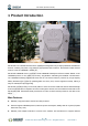
User Guide (Tech Document) 1 Product Introduction SenseCAP is an industrial wireless sensor network that integrates easy-to-deploy hardware and data API services, enabling low-power, long-distance environmental data collection. SenseCAP includes several versions, such as LoRaWAN, LoRaPP, etc. SenseCAP LoRaWAN version products include LoRaWAN Gateways and Sensor Nodes. Based on the LoRaWAN protocol, it can realize one-to-many, long-distance networking and bilateral communication.
User Guide (Tech Document) scenarios ⚫ Super long-distance communication: 10km in the line-of-sight scenario, 2km in the urban scenario ⚫ Easy-to-use cloud platform and API ⚫ Industrial protection rating IP66-rated enclosure, suitable for the outdoor environment at -40℃~70℃ ⚫ Easy-to-deploy, enabling people without engineering background to install the devices quickly ⚫ Modular design for the Sensor Nodes, including a Sensor Node Controller and a Sensor Probe, with a specially-designed bracket for
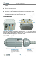
User Guide (Tech Document) Snap to open the device and you will see two parts. The Sensor Node Controller’s circuit shows a power switch, a RESET button, and an indicator LED as well as a mode button and serial ports, which will be used for firmware upgrading. The two parts connect and communicate via two spring connectors. Each Sensor Node comes with a bracket for easy installation on a pole or wall.
User Guide (Tech Document) 7 / 50 © 2008-2019 Seeed Technology Co., Ltd. All rights reserved. www.seeed.
User Guide (Tech Document) 2 Quick Start The main steps are listed for quick use. Please refer to the following section for more details. 1. Checklist. Unpack the package, check the list of devices, and check whether there are any omissions. 2. Assemble the gateway. 1) Install LoRa and 4G antennas. 2) Connect to the Internet (use Ethernet or install 4G card). 3) Connect the power supply. 3. Power on the gateway. 1) The LED indicator light will turn off after 2 seconds and the gateway will start normally.
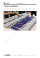
User Guide (Tech Document) 3 Device Installation In this chapter, we will introduce the gateway and sensor nodes, their respective installation processes, as well as the dos and don’ts. Before installing, please check the part list to ensure nothing is missing. 9 / 50 © 2008-2019 Seeed Technology Co., Ltd. All rights reserved. www.seeed.
User Guide (Tech Document) Part List 3.1.1 Gateway Part List The LoRa Gateway comes with a standard antenna. If you need ultra-long-distance communication, you will need to purchase a high-gain fiberglass antenna.
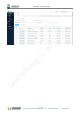
User Guide (Tech Document) 3.1.2 Sensor Node Part List The accessories for different sensors may vary. The common parts are as follows: Item Name Quantity 1 Sensor 1 2 Bracket 1 3 M4 Self-drilling Screw 4 4 M3 Self-drilling Screw 2 3.1.3 Other Accessories & Tool List For installing in different scenarios, you might need to purchase extra accessories or tools. Item Name (2.
User Guide (Tech Document) Gateway Installation 3.2.1 Gateway Installation Methods ⚫ Installing on a pole (Use the Mounts) Firstly, use M5 self-drilling screws (included in the package) to fasten the 4 brackets onto the gateway. And then use cable ties to fasten the gateway onto the pole. The recommended pole diameter is 70mm. Put cable ties through the holes of the bracket and pull to fasten onto the pole.
User Guide (Tech Document) ⚫ Installing on a pole (Use the Ferrules and Aluminum pieces) Firstly, use M5 self-drilling screws (included in the package) to fasten the 2 Aluminum pieces onto the gateway. And then use ferrules to fasten the gateway onto the pole. The recommended pole diameter is 76mm. Note: If the pole is made of metal, the antenna should be pulled higher than the metallic part of the pole, or the communication signal will have interfered.
User Guide (Tech Document) Note: The screws (that fasten gateway onto the wall) are not included in the package. Please prepare screws according to the wall materials (recommended screw diameter: 6mm). 3.2.2 Installation Precautions 1) In mountainous or thunderstorm-stricken areas, please take lightening protection measures. For the fiberglass LoRa antenna, you will need to install a lightening arrester and make sure it is connected to the ground.
User Guide (Tech Document) Note: The tape must be wound clockwise because the antenna is fastened clockwise. Otherwise, the antenna may loosen. If the sensor has wires, install threaded tubes: 3.2.3 Install SIM Card ⚫ Use the hex key (included in the package) to unscrew the 6 screws and open the lid. 15 / 50 © 2008-2019 Seeed Technology Co., Ltd. All rights reserved. www.seeed.
User Guide (Tech Document) ⚫ Swipe downward to open the SIM card socket, insert the Micro SIM card and swipe upward to lock the SIM card socket. Make sure it is installed correctly and close the lid with the screws. 3.2.4 Connecting to Ethernet Cable Unscrew to open the protection cap, plug the Ethernet cable through the cap and then into the Ethernet port. Screw to fasten this part. 3.2.
User Guide (Tech Document) Note: When installing the antenna, do not connect the power supply, otherwise it will cause damage to the antenna circuit! 3.2.6 Installing LoRa Antenna There are two kinds of LoRa antennas: the normal LoRa antenna (included in the package), and the fiberglass LoRa antenna (to be purchased separately). The installation method for the normal LoRa antenna is the same as that of the 4G antenna. Here we will introduce how to install the fiberglass LoRa antenna.
User Guide (Tech Document) 3) Use a 1-meter antenna feed line to connect the lightening arrester with the fiberglass antenna. 3.2.7 Installing Ground Cable Here we will connect the lightening arrester to the GND screw port on the gateway with a ground cable, and then connect the whole device to the ground. The image below shows the location of the GND port at the backside of the gateway. 18 / 50 © 2008-2019 Seeed Technology Co., Ltd. All rights reserved. www.seeed.
User Guide (Tech Document) 1 Gateway's ground screw port 2 1) Prepare two copper cables, a shorter one (approx. 30cm) for connecting the lightening arrester with the GND screw port (on the gateway), and a longer one for connecting the device to the ground. 2) Fasten the lightening arrester to the short copper cable with screws, and then connect the two copper cables to the GND screw port. Use the screw to connect and fasten them.
User Guide (Tech Document) Installing Sensor Node 3.3.1 Power On The power switch is hidden inside the device. Open the device and turn on the power before installing the sensors. Here is the step-by-step instruction: 1) Loosen the Sensor Probe by turning the cap counterclockwise. Use the white cap opener to make this process easier. The image below uses TH Sensor as an example and applies to all other SenseCAP sensors.
User Guide (Tech Document) 3.3.2 Installing the Sensor Node Bracket Specially designed for installing SenseCAP Sensor Nodes, the bracket consists of a bracket and a sliding cap. With designated screw-holes, the bracket helps fasten the Sensor Node firmly onto a pole or a wall. 1) To install on a pole, you can use zip ties to fasten the bracket (recommended pole dimension is 5070mm in diameter). Please refer to the following image for bracket directions. 21 / 50 © 2008-2019 Seeed Technology Co., Ltd.
User Guide (Tech Document) 2) To install on the wall or other surfaces, you can use self-drilling screws to fasten the bracket onto the surface. 3.3.3 Installing Sensor Nodes After installing brackets, let’s install sensors. 1) The Sensor Probe should be placed vertically downward with the label facing outward. Be consistent with the bracket gap. Make sure the circle part in the middle of Sensor Node is aligned with the middle of the bracket, and then press the Sensor Node to fit into the bracket.
User Guide (Tech Document) Note:Do not insert the Sensor Node into the bracket from the top, or it will not fasten the onto the bracket securely. 3.3.4 Dos and Don’ts in Installing Sensor Probes The same instruction applies to installing the different Sensor Nodes. However, there are some tips to keep in mind when installing certain Sensor Nodes.
User Guide (Tech Document) ⚫ CO2 Sensor The Sensor Probe can be fastened with self-drilling screws. Please refer to the image below for the probe direction. The end without the cables should point downward to prevent rain or dust from getting into the probe. Also, the device should be in a place with good ventilation. 24 / 50 © 2008-2019 Seeed Technology Co., Ltd. All rights reserved. www.seeed.
User Guide (Tech Document) 4 Network Configuration After installing the device, you need to test and configure the network. If the device is to be installed in a high place, you can also test and set up the network connection before installing it. 25 / 50 © 2008-2019 Seeed Technology Co., Ltd. All rights reserved. www.seeed.
User Guide (Tech Document) Gateway Network Configuration Make sure all antennas are correctly installed before powering on the gateway. Please note the device should be POWERED OFF when installing the antenna, or the antenna circuits might be damaged. 4.1.1 Connecting to Ethernet Please refer to the previous chapter to connect the gateway to the Ethernet cable and power cable. Power on the gateway and wait for 1~2 minutes.
User Guide (Tech Document) 4.1.2 Connecting to 4G Please refer to the previous chapter to install a SIM card. Please make sure it is a 4G SIM card because the device only supports the 4G network. Then connect the gateway to the Ethernet cable and power cable. Power on the gateway. The process and LED indications are the same as connecting to Ethernet (as shown above). 27 / 50 © 2008-2019 Seeed Technology Co., Ltd. All rights reserved. www.seeed.
User Guide (Tech Document) Device Status Check, Dos & Don’ts 4.2.1 Checking Gateway Connection Status After powering on the gateway, you can check gateway working status through the following methods: ⚫ Light Indicator: ON means the gateway is connected and in working condition, flashing means network latency or no connection. When the connection resumes, the indicator will be ON.
User Guide (Tech Document) Note: 1. Each device will constantly sync with the cloud within 1 minute of connecting to the network. This process takes up the LoRa communication channel. When multiple devices are powered on and connected to the network at the same time, it might congest the LoRa network, leading to failure to access the network. Hence, we suggest that you wait one minute after turning on one Sensor Node to turn on the next one. 2.
User Guide (Tech Document) ① Sensor Count, If the display is 0, it means that the network access is abnormal, and the sensor needs to be restarted to enter the network again. Greater than 0 means normal. ② Online Status, “online” or “offline”. Note: After joining the network, the Sensor Count must be greater than 0, otherwise the node cannot use functions such as data charts. If it is 0, use the "RESET" button of the node to re-enter the network and return to normal.
User Guide (Tech Document) 5 SenseCAP Portal The main function of the SenseCAP Portal is to manage SenseCAP devices and to store data. It is built on Azure, a secure and reliable cloud service from Microsoft. You can apply for an account and bind all devices to this account. SenseCAP provides the web portal and API. The web portal includes Dashboard, Device Management, Data Management, and Access Key Management, while API is open to users for further development. 31 / 50 © 2008-2019 Seeed Technology Co.
User Guide (Tech Document) Explanation of Terms and Tags Term Explanation EUI The unique identifier for each SenseCAP device Access Key The key for accessing API Cloud Service The general term that includes a series of services: cloud platform, API, and App, etc. Dashboard The interface that monitors and displays data SenseCAP App The iOS/Android tool that binds the devices to your account.
User Guide (Tech Document) Account and Login 33 / 50 © 2008-2019 Seeed Technology Co., Ltd. All rights reserved. www.seeed.
User Guide (Tech Document) Portal Website: http://sensecap.seeed.cc ① Select register account, enter email information and click "register", the registered email will be sent to the user's mailbox. ② Open the "SenseCAP…"Email, click the jump link, fill in the relevant information, and complete the registration. ③ Return to the login interface and complete the login. Note: If you can't find the email, it may be automatically identified as "spam" and put in the "trash can".
User Guide (Tech Document) Dashboard ① Add “Scene” or “Chart”. ② Devices Overview: displays the total number of devices. ③ Monitoring: count all offline devices and low power devices. ④ Data update interval: sets how and at what time the page (web page) is refreshed. ⑤ Announcement: prompt for portal version upgrade and other information. ⑥ Scene: the corresponding visual display module is configured according to the sensor area.
User Guide (Tech Document) ① Customize the name, create the scene display of "station-1", and select “Add measurement type”. ② Select the measurement data to be displayed under the group of "station-1" and confirm. 5.3.2 Configure Charts You can create charts to show the info such as measurement type, device EUI, and time range, etc. 36 / 50 © 2008-2019 Seeed Technology Co., Ltd. All rights reserved. www.seeed.
User Guide (Tech Document) ① Select “Add”- “Chart”. ② Customize the name and select “add measure type". ③ Select the data type and time to display. ④ Select group. ⑤ Select the specific sensor node under the group. ⑥ Select the measurement type. ⑦ Confirm. Note: Only one measurement type can be added per chart. Add up to 5 curves per chart. 37 / 50 © 2008-2019 Seeed Technology Co., Ltd. All rights reserved. www.seeed.
User Guide (Tech Document) Device Management Here you are offered several methods to manage SenseCAP devices, including Gateway Management, Node Group Management, and Sensor Node Management. 5.4.1 Gateway ① Filter the gateway based on EUI, frequency, status, and registration time. ② List of gateways, displaying EUI, name, status, and so on. ③ Click EUI to enter the device details page to view basic information, location, binding, etc. 5.4.
User Guide (Tech Document) 5.4.3 Sensor Node Management At the page of Sensor Node, you can see all the Sensor Nodes bound to your account. ① Devices contain types such as "LoRa" and "NB-IoT" and can be viewed by category. ② Filter criteria, according to EUI, frequency, group, status, registration time filter node. ③ Sensor Node list, displaying EUI, name, status, data type, and so on. ④ Click EUI to enter the device details page. 39 / 50 © 2008-2019 Seeed Technology Co., Ltd. All rights reserved. www.
User Guide (Tech Document) 5.4.4 Setting Sensor Node Collects Interval ① On the device details page, click "Setting". ② Configure collection frequency (5 minutes ~ 30 days). ③ View the record of the command. 5.4.5 Delete Device ① On the device details page, click "Binding". ② Remove from organization: delete the device. ③ Transfer to other organization: transfer device to another account. 40 / 50 © 2008-2019 Seeed Technology Co., Ltd. All rights reserved. www.seeed.
User Guide (Tech Document) Data Management ⚫ Table ① Devices contain types such as "LoRa" and "NB-IoT" and can be viewed by category. ② Filter criteria, according to EUI, frequency, group, status, registration time filter node. ③ List of data showing EUI, device name, data type, measurements, collection and upload time, etc. ④ Click EUI to enter the device details page and view the basic information of the Sensor Node. ⚫ Graph 41 / 50 © 2008-2019 Seeed Technology Co., Ltd. All rights reserved. www.
User Guide (Tech Document) ① Add a new page, enter a page name, and select the number of rows and columns. ② Select the measurements and time intervals to be displayed. ③ Select specific sensor data. Note: Up to three rows and three columns can be set per page, and multiple pages can be created. Please refer to the Dashboard chart for detailed steps. 42 / 50 © 2008-2019 Seeed Technology Co., Ltd. All rights reserved. www.seeed.
User Guide (Tech Document) Security 5.6.1 Check Account Info In the Account Management page, you can check your account info and click to change the info. 5.6.2 Access Key Management Access Key is used for accessing API. And Security Credentials provides functions such as “Create”, “Update”, and “Check” for you to manage Access Key. 43 / 50 © 2008-2019 Seeed Technology Co., Ltd. All rights reserved. www.seeed.
User Guide (Tech Document) 6 SenseCAP App Instructions As a tool, SenseCAP App is used to bind devices to your account and check device basic info. Download SenseCAP App ⚫ For iOS, please search for “SenseCAP” in the App Store and download it. ⚫ For Android, you can download the App from http://sensecap-app-download.seeed.cn 44 / 50 © 2008-2019 Seeed Technology Co., Ltd. All rights reserved. www.seeed.
User Guide (Tech Document) Bind Devices ⚫ Scan QR Code Click “Bind” on the upper-right corner to enter the device binding page. Scan the QR code on the device to bind the device to your account. If you do not set it to a designated group, the device will be put into the “default” group. ⚫ Manually fill in the EUI If the QR code sticker is damaged, you can manually fill in the EUI of the device to bind the device to your account.
User Guide (Tech Document) 6.2.1 Group Management 6.2.2 Check Groups Click “Group” on the upper-left corner to check the list of Groups and manage Groups. 6.2.3 Create New Groups On the upper right corner, click “Create” to add a new Group, fill in the group name, click “Confirm”. 46 / 50 © 2008-2019 Seeed Technology Co., Ltd. All rights reserved. www.seeed.
User Guide (Tech Document) Device Management 6.3.1 Check Device On the SenseCAP App homepage, the devices are shown in Groups. You can click “Unfold” to show the devices in respective Groups. The info shown here includes the device name, type, and EUI. 6.3.2 Device Details Click device name to enter its respective page, showing device name, type, EUI, status, time of the latest 47 / 50 © 2008-2019 Seeed Technology Co., Ltd. All rights reserved. www.seeed.
User Guide (Tech Document) message and 10 recent RAW messages. User Profile 6.4.1 Check Current Account At the “My Profile” page, you can check the current account. 48 / 50 © 2008-2019 Seeed Technology Co., Ltd. All rights reserved. www.seeed.
User Guide (Tech Document) 6.4.2 Settings You can change the map service provider based on the actual needs in the local areas where you deploy the solution. 6.4.3 Sign Out Click “Sign Out” to log out of your current account. 49 / 50 © 2008-2019 Seeed Technology Co., Ltd. All rights reserved. www.seeed.
User Guide (Tech Document) 7 API Instruction SenseCAP API is for users to manage IoT devices and data. It combines three types of API methods: HTTP protocol, MQTT protocol, and Websocket protocol. ⚫ With HTTP API, users can manage LoRa and NB-IoT devices, to get RAW data or historical data. ⚫ With MQTT API, users can subscribe to the sensor's real-time measurement data through the MQTT protocol. ⚫ With Websocket API, users can get real-time measurement data of sensors through Websocket protocol.