User Manual SenseCAP LoRaWAN Sensor User Manual Version: V1.1 1 / 37 © 2008-2019 Seeed Technology Co., Ltd. All rights reserved. www.seeed.
User Manual Table of Contents 1 2 3 4 5 6 7 Product Introduction .............................................................................................................................. 3 Key Parameters of the Sensor Node .................................................................................................... 5 Introduction of Key Parameters ................................................................................................. 5 Get Device EUI, App EUI and Key............
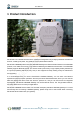
User Manual 1 Product Introduction SenseCAP is an industrial wireless sensor network that integrates easy-to-deploy hardware and data API services, enabling low-power, long-distance environmental data collection. SenseCAP LoRaWAN products include LoRaWAN Gateways and Sensor Nodes. Based on the LoRaWAN protocol, it can realize one-to-many, long-distance networking and bilateral communication. The LoRaWAN Gateway supports Ethernet and 4G.
User Manual 4 / 37 © 2008-2019 Seeed Technology Co., Ltd. All rights reserved. www.seeed.
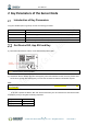
User Manual 2 Key Parameters of the Sensor Node Introduction of Key Parameters Using the LoRaWAN protocol generally involves the following parameters. Parameters Description Device EUI Unique identification of device, one of the network join parameters. Device Code For device binding and API call. App EUI Unique identification of application, one of the network join parameters. App Key Application key, one of the network join parameters.
User Manual { "code": "0", "data": { "nodeEui": "2CF7F12014700297", "deviceCode": "34BF25920A4EFBF4", "lorawanInformation": { "dev_eui": "2CF7F12014700297", "app_eui": "8000000000000006", "app_key": "6FD0EF47CBC6E00F1921A08C2E94E8E5" } }, "time": 0.019 } Tips: The SenseCAP LoRaWAN Sensor can modify to EUI and Key. Please refer to the following sections. 6 / 37 © 2008-2019 Seeed Technology Co., Ltd. All rights reserved. www.seeed.
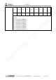
User Manual 3 Connect to Gateway and Servers. Configuration Overview Device Parameters LoRaWAN MAC version 1.0.2 LoRaWAN Regional Parameters revision B Join Type OTAA Device EUI Refer to section 2 for details. App EUI Refer to section 2 for details. App Key Refer to section 2 for details. Frequency Plans EU868 (LoRa-S-868XXX-XX) Uplink: 868.1 - SF7BW125 to SF12BW125 868.3 - SF7BW125 to SF12BW125 and SF7BW250 868.5 - SF7BW125 to SF12BW125 867.1 - SF7BW125 to SF12BW125 867.
User Manual Channel 64 to 71 903 904.6 906.2 907.8 909.4 911 912.6 914.2 500kHz DR4 Sub-band Sub-band Sub-band Sub-band Sub-band Sub-band Sub-band Sub-band 1 2 3 4 5 6 7 8 Downlink: 923.3 - SF7BW500 to SF12BW500 923.9 - SF7BW500 to SF12BW500 924.5 - SF7BW500 to SF12BW500 925.1 - SF7BW500 to SF12BW500 925.7 - SF7BW500 to SF12BW500 926.3 - SF7BW500 to SF12BW500 926.9 - SF7BW500 to SF12BW500 927.5 - SF7BW500 to SF12BW500 8 / 37 © 2008-2019 Seeed Technology Co., Ltd.
User Manual Connect to the SenseCAP Gateway (Recommend Product) It only takes 4 steps to get started and install. Step1: Scan code to bind the Gateway and Sensors. Step2: Turn on the Gateway and Sensors. 9 / 37 © 2008-2019 Seeed Technology Co., Ltd. All rights reserved. www.seeed.
User Manual Step3: Log on to the SenseCAP Portal to view the data. Step4: Install the gateway and sensors. Refer to SenseCAP LoRaWAN Gateway for more details: https://www.seeedstudio.com/LoRaWAN-Gateway-EU868-p-4305.html 10 / 37 © 2008-2019 Seeed Technology Co., Ltd. All rights reserved. www.seeed.
User Manual Connect to a Standard LoRaWAN Gateway SenseCAP Sensor Nodes support standard LoRaWAN 1.0.2 protocol, making it possible to connect to standard LoRaWAN gateways and servers. 3.3.1 Power On The power switch is hidden inside the device. Open the device and turn on the power before installing the sensors. Here is the step-by-step instruction: 1) Loosen the Sensor Probe by turning the cap counterclockwise. Use the white cap opener to make this process easier.
User Manual 3) After the device is connected to the network, connect the Sensor Probe back with the Sensor Node Controller by turning it clockwise. Please note that the labels on both parts should be aligned as shown in the image below, otherwise the two parts will not be attached to function properly and data will not be uploaded. 3.3.2 Sensor Node Working Status You can refer to the LED indicator for the Sensor Node for its working status. Please see the status explanations in the image below: 3.3.
User Manual You can learn more about LPS8 Gateway: https://www.seeedstudio.com/LPS8-Indoor-LoRaWAN-Gateway-Included-SX1308-LoRa-Concentrator-p4251.html 1) Gateway Registration on TTN TTN website: https://www.thethingsnetwork.org Follow the instruction to create your account, and access “Console”. Register Gateway: ① Gateway EUI: View the labels on the gateway. 13 / 37 © 2008-2019 Seeed Technology Co., Ltd. All rights reserved. www.seeed.
User Manual Select ‘I’m using the legacy packet forwarder’. ② Frequency Plan: View the labels on the gateway. ③ Router: Select the router that is right for you. ④ Register. Gateway Status displays connected, indicating successful registration. 2) Create an Application TTN console → Application → Add application ① ② ③ ④ Application ID: Enter a unique name. Description: Enter a description. Handler registration: Select the same handler as the gateway router. Add application.
User Manual ① ② ③ ④ Application → Application EUIS → Manage EUIs. →Add EUI. Enter the node’s AppEui that you got in the 3.1 step. →Add EUI. 15 / 37 © 2008-2019 Seeed Technology Co., Ltd. All rights reserved. www.seeed.
User Manual 3) Sensor Node Registration on TTN Application → Devices → register device ① ② ③ ④ ⑤ Device ID: Enter a unique name. Device EUI: Enter the node’s Device EUI that you got in the previous step. App Key: Enter the node’s App Key that you got in the previous step. App EUI: Select the node’s App EUI. Register. 16 / 37 © 2008-2019 Seeed Technology Co., Ltd. All rights reserved. www.seeed.
User Manual 4) Gateway Settings Find radio settings or frequency settings in the background of the gateway. Configure the gateway as Sub-band 2. Please refer to the Configuration Overview for channel settings. 17 / 37 © 2008-2019 Seeed Technology Co., Ltd. All rights reserved. www.seeed.
User Manual 5) Power on Refer to the previous steps. 18 / 37 © 2008-2019 Seeed Technology Co., Ltd. All rights reserved. www.seeed.
User Manual 6) Checking Data on the TTN On the Device Overview page, Status turns green. On the Data page, data package is uploaded. For the format of the payload, refer to the Decoding section. 19 / 37 © 2008-2019 Seeed Technology Co., Ltd. All rights reserved. www.seeed.
User Manual 4 How to Modify the Key Parameters Preparation Tools USB to TTL Serial Tool *1 Software SenseCAP Node Configuration Tool Windows: SenseCAP-Node-Configuration-Tool-x.x.x.exe Mac: SenseCAP-Node-Configuration-Tool-x.x.x.dmg Download: https://github.com/Seeed-Solution/SenseCAP-Node-ConfigurationTool/releases/tag/v1.0.3 Connect serial ports (as shown in the image below), turn on the power, launch the serial port monitoring tool on your computer.
User Manual Select the COM Port that your tool uses, and click “CONNECT”. Power the Sensor Node. Press “SET” button on the Sensor Controller, meanwhile press “RESET” once, and you will see “SenseCAP”. 21 / 37 © 2008-2019 Seeed Technology Co., Ltd. All rights reserved. www.seeed.
User Manual Modify the Device EUI, App EUI & Key and Data Interval (1) ①Device EUI (16 bit) ②App EUI (16 bit) ③App Key (32 bit) ④Data Interval (Sensor collection cycle) (2) For example: modify the Device EUI ① Write the new Device EUI. ② Click “WRITE” 22 / 37 © 2008-2019 Seeed Technology Co., Ltd. All rights reserved. www.seeed.
User Manual 23 / 37 © 2008-2019 Seeed Technology Co., Ltd. All rights reserved. www.seeed.
User Manual Modify the Sub-band Example: You can type commands at the green cursor: b Set the sub-band to 7: 7 24 / 37 © 2008-2019 Seeed Technology Co., Ltd. All rights reserved. www.seeed.
User Manual Modify the Data Interval Remotely (1) Using the Network Server’s portal or API to send downlink command, then the Node will respond to the ack. Note: The downlink command takes effect and responds the next time the node uploads data.
User Manual 5 Decoding TTN payload decoding script for SenseCAP LoRaWAN: https://github.com/Seeed-Solution/TTN-Payload-Decoder/ In the gateway or server background, similar packets can be viewed. (If the data is encrypted, it usually needs to be decrypted using base64) Note: With successful access to the network, please connect the Sensor Probe back to the Sensor Node Controller by turning it clockwise.
User Manual Packet Parsing Packet Initialization After being powered on or reboot, SenseCAP Sensor Nodes will be connected to the network using the OTAA activation method.
User Manual Divide the data into 3 sections 1 Air 010110B0680000 01 is the channel number. 0110 is 0x1001(little-endian byte order), which is Temperature the measurement ID for air temperature. B0680000 is actually 0x000068B0, whose equivalent decimal value is 26800. Divide it by 1000, and you’ll get the actual measurement value for air temperature as 26.8℃. 2 Air Humidity 01021088F40000 0210 is 0x1002(little-endian byte order), which is the measurement ID for air humidity.
User Manual E08D0500 is actually 0x00058DE0, whose equivalent decimal value is 364000. Divide it by 1000, and you’ll get the actual measurement value for CO2 as 364ppm. 3 CRC 9802 The CRC verification part. 5.1.3 Example 3 - Soil Moisture and Temperature Sensor: Soil Moisture and Temperature Sensor measurement packet: 010610007D0000010710725100009A21 Divide the data into 3 sections 1 Soil 010610007D0000 01 is the channel number.
User Manual Moisture as 20.85%. 3 CRC 9A21 The CRC verification part. 5.1.4 Example 4 – Light Intensity Sensor: Light Intensity Sensor measurement packet: 010310A0320000C3B6 Divide the data into 3 sections 1 Light Intensity 010310A0320000 01 is the channel number. 0310 is 0x1003(little-endian byte order), which is the measurement ID for Light Intensity. A0320000 is actually 0x000032A0, whose equivalent decimal value is 12960.
User Manual 284A1406 is actually 0x06144A28, whose equivalent decimal value is 101993000. Divide it by 1000, and you’ll get the actual measurement value for Barometric Pressure as 101993Pa. 3 CRC 52B7 The CRC verification part. 31 / 37 © 2008-2019 Seeed Technology Co., Ltd. All rights reserved. www.seeed.
User Manual Battery Information Please note the counter number. After 10 packets, it will follow one special packet with battery info. You can either ignore this packet or get rid of the battery info in your code.
User Manual 58660000 is actually 0x00006658, whose equivalent decimal value is 26200. Divide it by 1000, and you’ll get the actual measurement value for air temperature as 26.2℃. 2 Humidity 01021070F80000 0210 is 0x1002(little-endian byte order), which is the measurement ID for air humidity. 70F80000 is actually 0x0000F870, whose equivalent decimal value is 63600. Divide it by 1000, and you’ll get the actual measurement value for air humidity as 63.6%RH. 3 CRC 443E The CRC verification part.
User Manual 6 Device Installation Installing Sensor Node 6.1.1 Installing the Sensor Node Bracket Specially designed for installing SenseCAP Sensor Nodes, the bracket consists of a bracket and a sliding cap. With designated screw-holes, the bracket helps fasten the Sensor Node firmly onto a pole or a wall. 1) To install on a pole, you can use zip ties to fasten the bracket (recommended pole dimension is 5070mm in diameter). Please refer to the following image for bracket directions.
User Manual surface. 6.1.2 Installing Sensor Nodes After installing brackets, let’s install sensors. 1) The Sensor Probe should be placed vertically downward with the label facing outward. Be consistent with the bracket gap. Make sure the circle part in the middle of Sensor Node is aligned with the middle of the bracket, and then press the Sensor Node to fit into the bracket. A click/snap sound indicates that the Sensor Node has been installed successfully.
User Manual 6.1.3 Dos and Don’ts in Installing Sensor Probes The same instruction applies to installing the different Sensor Nodes. However, there are some tips to keep in mind when installing certain Sensor Nodes. ⚫ Light Sensor The Sensor Probe of the Light Sensor needs to be placed vertically upward, and there should not be anything obstructing sunlight from the Sensor Probe. ⚫ CO2 Sensor The Sensor Probe can be fastened with self-drilling screws.
User Manual 7 Trouble Shooting Sensor Node not join the network, how to do? 1. Check the gateway channels configuration. Make sure the gateway and Sensor Node have the same uplink and downlink channels. 2. Check the gateway real-time log and RESET the sensor to see if there are any sensor data packets. If there are packets, check whether the gateway is sending downlink packets. 3.