STM32F030x4 STM32F030x6 STM32F030x8 STM32F030xC Value-line ARM®-based 32-bit MCU with up to 256-KB Flash, timers, ADC, communication interfaces, 2.4-3.6 V operation Datasheet - production data Features • Core: ARM® 32-bit Cortex®-M0 CPU, frequency up to 48 MHz • Memories – 16 to 256 Kbytes of Flash memory – 4 to 32 Kbytes of SRAM with HW parity • CRC calculation unit • Reset and power management – Digital & I/Os supply: VDD = 2.4 V to 3.6 V – Analog supply: VDDA = VDD to 3.
STM32F030x4/6/8/C Contents Contents 1 Introduction . . . . . . . . . . . . . . . . . . . . . . . . . . . . . . . . . . . . . . . . . . . . . . . . 8 2 Description . . . . . . . . . . . . . . . . . . . . . . . . . . . . . . . . . . . . . . . . . . . . . . . . . 9 3 Functional overview . . . . . . . . . . . . . . . . . . . . . . . . . . . . . . . . . . . . . . . . 12 3.1 ARM®-Cortex®-M0 core with embedded Flash and SRAM . . . . . . . . . . . 12 3.2 Memories . . . . . . . . . . . . . . . . . . . . .
Contents STM32F030x4/6/8/C 3.15 Serial peripheral interface (SPI) . . . . . . . . . . . . . . . . . . . . . . . . . . . . . . . . 23 3.16 Serial wire debug port (SW-DP) . . . . . . . . . . . . . . . . . . . . . . . . . . . . . . . . 23 4 Pinouts and pin descriptions . . . . . . . . . . . . . . . . . . . . . . . . . . . . . . . . . 24 5 Memory mapping . . . . . . . . . . . . . . . . . . . . . . . . . . . . . . . . . . . . . . . . . . . 38 6 Electrical characteristics . . . . . . . . . . . . . . .
STM32F030x4/6/8/C 7 Contents Package characteristics . . . . . . . . . . . . . . . . . . . . . . . . . . . . . . . . . . . . . 81 7.1 Package mechanical data . . . . . . . . . . . . . . . . . . . . . . . . . . . . . . . . . . . . 81 7.2 Thermal characteristics . . . . . . . . . . . . . . . . . . . . . . . . . . . . . . . . . . . . . . 93 7.2.1 Reference document . . . . . . . . . . . . . . . . . . . . . . . . . . . . . . . . . . . . . . . 93 8 Part numbering . . . . . . . . . . . . . . . . . . . .
STM32F030x4/6/8/C List of tables List of tables Table 1. Table 2. Table 3. Table 4. Table 5. Table 6. Table 7. Table 8. Table 9. Table 10. Table 11. Table 12. Table 13. Table 14. Table 15. Table 16. Table 17. Table 18. Table 19. Table 20. Table 21. Table 22. Table 23. Table 24. Table 25. Table 26. Table 27. Table 28. Table 29. Table 30. Table 31. Table 32. Table 33. Table 34. Table 35. Table 36. Table 37. Table 38. Table 39. Table 40. Table 41. Table 42. Table 43. Table 44. Table 45. Table 46. Table 47.
List of tables Table 48. Table 49. Table 50. Table 51. Table 52. Table 53. Table 54. Table 55. Table 56. Table 57. Table 58. Table 59. Table 60. Table 61. Table 62. Table 63. Table 64. Table 65. 6/96 STM32F030x4/6/8/C I/O AC characteristics . . . . . . . . . . . . . . . . . . . . . . . . . . . . . . . . . . . . . . . . . . . . . . . . . . . . . 70 NRST pin characteristics . . . . . . . . . . . . . . . . . . . . . . . . . . . . . . . . . . . . . . . . . . . . . . . . . . 71 ADC characteristics . . . . . .
STM32F030x4/6/8/C List of figures List of figures Figure 1. Figure 2. Figure 3. Figure 4. Figure 5. Figure 6. Figure 7. Figure 8. Figure 9. Figure 10. Figure 11. Figure 12. Figure 13. Figure 14. Figure 15. Figure 16. Figure 17. Figure 18. Figure 19. Figure 20. Figure 21. Figure 22. Figure 23. Figure 24. Figure 25. Figure 26. Figure 27. Figure 28. Figure 29. Figure 30. Figure 31. Figure 32. Figure 33. Figure 34. Figure 35. Figure 36. Figure 37. Figure 38. Block diagram . . . . . . . . . . . . . . . . . .
STM32F030x4/6/8/C 1 Introduction Introduction This datasheet provides the ordering information and mechanical device characteristics of the STM32F030x4/6/8/C microcontrollers. This document should be read in conjunction with the STM32F0x0xx reference manual (RM0360). The reference manual is available from the STMicroelectronics website www.st.com. For information on the ARM® Cortex®-M0 core, please refer to the Cortex®-M0 Technical Reference Manual, available from the www.arm.com website.
Description 2 STM32F030x4/6/8/C Description The STM32F030x4/6/8/C microcontrollers incorporate the high-performance ARM® Cortex®-M0 32-bit RISC core operating at a 48 MHz frequency, high-speed embedded memories (up to 256 Kbytes of Flash memory and up to 32 Kbytes of SRAM), and an extensive range of enhanced peripherals and I/Os.
STM32F030x4/6/8/C Description Table 2. STM32F030x4/6/8/C family device features and peripheral counts STM32 F030F4 STM32 F030K6 STM32 F030C6 STM32 F030C8 STM32 F030CC STM32 F030R8 STM32 F030RC Flash (Kbytes) 16 32 32 64 256 64 256 SRAM (Kbytes) 4 4 4 8 32 8 32 Peripheral Advanced control Timers General purpose 1 (16-bit) 4 (16-bit)(1) 4 (16-bit)(1) 4 (16-bit)(1) Basic 5 (16-bit) 1 (16-bit)(2) 2 (16-bit) 1 (16-bit)(2) 2 (16-bit) (3) - - - (3) (3) SPI Comm.
Description STM32F030x4/6/8/C Figure 1. Block diagram 9'' 2EO )ODVK LQWHUIDFH 6HULDO :LUH 'HEXJ 6:&/. 6:',2 DV $) 65$0 FRQWUROOHU 19,& %XV PDWUL[ &257(; 0 &38 I+&/. 0+] )ODVK XS WR .% ELWV 65$0 .% 325 5HVHW ,QW 5& /6 3// *3,2 SRUW % 3&> @ *3,2 SRUW & 3' *3,2 SRUW ' 3)> @ 3)> @ *3,2 SRUW ) 5(6(7 &/2&. &21752/ $+% GHFRGHU 3%> @ 6833/< 683(59,6,21 325 3'5 # 9''$ 5& +6 0+] *3,2 SRUW $ $+%3&/. $3%3&/. $'&&/. 86$57&/. +&/. )&/.
STM32F030x4/6/8/C Functional overview 3 Functional overview 3.1 ARM®-Cortex®-M0 core with embedded Flash and SRAM The ARM® Cortex®-M0 processor is the latest generation of ARM processors for embedded systems. It has been developed to provide a low-cost platform that meets the needs of MCU implementation, with a reduced pin count and low-power consumption, while delivering outstanding computational performance and an advanced system response to interrupts.
Functional overview 3.4 STM32F030x4/6/8/C Cyclic redundancy check calculation unit (CRC) The CRC (cyclic redundancy check) calculation unit is used to get a CRC code using a configurable generator polynomial value and size. Among other applications, CRC-based techniques are used to verify data transmission or storage integrity. In the scope of the EN/IEC 60335-1 standard, they offer a means of verifying the Flash memory integrity.
STM32F030x4/6/8/C 3.5.4 Functional overview Low-power modes The STM32F030x4/6/8/C microcontrollers support three low-power modes to achieve the best compromise between low power consumption, short startup time and available wakeup sources: • Sleep mode In Sleep mode, only the CPU is stopped. All peripherals continue to operate and can wake up the CPU when an interrupt/event occurs. • Stop mode Stop mode achieves very low power consumption while retaining the content of SRAM and registers.
Functional overview STM32F030x4/6/8/C Figure 2. Clock tree &,)4&#,+ TO &LASH PROGRAMMING INTERFACE (3) TO ) # 393#,+ ,3% -(Z (3) (3) 2# (#,+ 0,,32# 0,,-5, 0,, X X X 37 (3) 0,,#,+ (3% !(" !(" PRESCALER 393#,+ #33 /3#?/54 /3#?). -(Z (3% /3# -(Z (3) (3) 2# /3# ?).
STM32F030x4/6/8/C 3.8 Functional overview Direct memory access controller (DMA) The 5-channel general-purpose DMA manages memory-to-memory, peripheral-to-memory and memory-to-peripheral transfers. The DMA supports circular buffer management, removing the need for user code intervention when the controller reaches the end of the buffer. Each channel is connected to dedicated hardware DMA requests, with support for software trigger on each channel.
Functional overview 3.10 STM32F030x4/6/8/C Analog to digital converter (ADC) The 12-bit analog to digital converter has up to 16 external and two internal (temperature sensor, voltage reference measurement) channels and performs conversions in single-shot or scan modes. In scan mode, automatic conversion is performed on a selected group of analog inputs. The ADC can be served by the DMA controller.
STM32F030x4/6/8/C 3.11 Functional overview Timers and watchdogs The STM32F030x4/6/8/C devices include up to six general-purpose timers, two basic timers and one advanced control timer. Table 5 compares the features of the different timers. Table 5.
Functional overview 3.11.1 STM32F030x4/6/8/C Advanced-control timer (TIM1) The advanced-control timer (TIM1) can be seen as a three-phase PWM multiplexed on six channels. It has complementary PWM outputs with programmable inserted dead times. It can also be seen as a complete general-purpose timer.
STM32F030x4/6/8/C Functional overview The TIM15, TIM16 and TIM17 timers can work together, and TIM15 can also operate withTIM1 via the Timer Link feature for synchronization or event chaining. TIM15 can be synchronized with TIM16 and TIM17. TIM15, TIM16 and TIM17 have a complementary output with dead-time generation and independent DMA request generation. Their counters can be frozen in debug mode. 3.11.3 Basic timers TIM6 and TIM7 These timers can be used as a generic 16-bit time base. 3.11.
Functional overview 3.12 STM32F030x4/6/8/C Real-time clock (RTC) The RTC is an independent BCD timer/counter. Its main features are the following: • Calendar with subseconds, seconds, minutes, hours (12 or 24 format), week day, date, month, year, in BCD (binary-coded decimal) format. • Automatic correction for 28, 29 (leap year), 30, and 31 day of the month. • Programmable alarm with wake up from Stop and Standby mode capability. • Periodic wakeup unit with programmable resolution and period.
STM32F030x4/6/8/C Functional overview In addition, I2C1 provides hardware support for SMBUS 2.0 and PMBUS 1.1: ARP capability, Host notify protocol, hardware CRC (PEC) generation/verification, timeouts verifications and ALERT protocol management The I2C interfaces can be served by the DMA controller. Refer to Table 7 for the differences between I2C1 and I2C2. Table 7.
Functional overview STM32F030x4/6/8/C 1. Where X means supported. 2. Not available on STM32F030x4/6 devices. 3. Available only on STM32F030xC devices. 3.15 Serial peripheral interface (SPI) Up to two SPIs are able to communicate up to 18 Mbit/s in slave and master modes in fullduplex and half-duplex communication modes. The 3-bit prescaler gives 8 master mode frequencies and the frame size is configurable from 4 bits to 16 bits.
STM32F030x4/6/8/C Pinouts and pin descriptions 3' 3& 3& 3& 3$ 3$ 3% 3% 3% 3% 3% /4)3 3) 3) 3$ 3$ 3$ 3$ 3$ 3$ 3& 3& 3& 3& 3% 3% 3% 3% 3$ 3$ 3$ 3$ 3& 3& 3% 3% 3% 3% 3% 966 9'' 9'' 3& 3& 26& B,1 3& 26& B287 3) 26&B,1 3) 26&B287 1567 3& 3& 3& 3&
Pinouts and pin descriptions STM32F030x4/6/8/C 3% 3% 3% 3% 3% 3' 3& 3& 3& 3$ 3$ 9'' 966 3$ 3$ 3$ 3$ 3$ 3$ 3& 3& 3& 3& 3% 3% 3% 3% 3$ 3$ 3$ 3$ 3& 3& 3% 3% 3% 3% 3% 966 9'' /4)3 3$ 966 9'' 9'' 3& 3& 26& B,1 3& 26& B287 3) 26&B,1 3) 26&B287 1567 3&
STM32F030x4/6/8/C Pinouts and pin descriptions 9'' 966 3% 3% %227 3% 3% 3% 3% 3% 3$ 3$ Figure 6.
Pinouts and pin descriptions STM32F030x4/6/8/C Figure 8. TSSOP20 20-pin package pinout (top view) 3$ 3) 26&B,1 3$ 3) 26&B287 3$ 1567 3$ 9''$ 9'' 3$ 966 3$ 3% 3$ 3$ 3$ 3$ 3$ 3$ %227 06Y 9 Table 10.
STM32F030x4/6/8/C Pinouts and pin descriptions Table 11.
Pinouts and pin descriptions STM32F030x4/6/8/C Table 11.
STM32F030x4/6/8/C Pinouts and pin descriptions Table 11.
Pinouts and pin descriptions STM32F030x4/6/8/C Table 11.
STM32F030x4/6/8/C Pinouts and pin descriptions Table 11.
Pinouts and pin descriptions STM32F030x4/6/8/C Table 11. STM32F030x4/6/8/C pin definitions (continued) Pin functions LQFP48 LQFP32 TSSOP20 I/O structure LQFP64 Pin name (function after reset) Pin type Pin number 63 47 32 15 VSS S Ground 64 48 1 16 VDD S Digital power supply Notes Alternate functions Additional functions 1. PC13, PC14 and PC15 are supplied through the power switch.
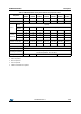
DocID024849 Rev 2 Pin name AF0 AF1 PA0 - PA1 EVENTOUT PA2 TIM15_CH1(2)(3) PA3 TIM15_CH2(2)(3) PA4 SPI1_NSS PA5 SPI1_SCK USART1_CTS(1) USART2_CTS(2)(3) USART1_RTS(1) USART2_RTS(2)(3) USART1_TX(1) USART2_TX(2)(3) USART1_RX(1) USART2_RX(2)(3) USART1_CK(1) USART2_CK(2)(3) - AF2 AF3 AF4 AF5 AF6 - - USART4_TX(2) - - - - USART4_RX(2) TIM15_CH1N(2) - - - - - - - - - - - - - TIM14_CH1 USART6_TX(2) - - - - USART6_RX(2) - TIM16_CH1 EVENTOUT PA6 SPI1_MISO TIM3_CH1
/96 3. This feature is available on STM32F030x8 devices only. Table 13.
3. This feature is available on STM32F030x8 devices only. STM32F030x4/6/8/C 2. This feature is available on STM32F030x4 and STM32F030x6 devices only.
STM32F030x4/6/8/C Table 14.
STM32F030x4/6/8/C 5 Memory mapping Memory mapping Figure 9. STM32F030x4/6/8/C memory map [)))) )))) [ )) $+% [( [( [ &RUWH[ 0 LQWHUQDO SHULSKHUDOV 5HVHUYHG [& [ )) $+% [ 5HVHUYHG [$ [ $3% [ ))) )))) [ ))) ) [ 2SWLRQ %\WHV [ 5HVHUYHG 6\VWHP PHPRU\ [ [ ))) & $3% [ [ 5HVHUYHG [ 3HULSKHUDOV [ )ODVK PHPRU\ [
Memory mapping STM32F030x4/6/8/C Table 17.
STM32F030x4/6/8/C Memory mapping Table 17.
STM32F030x4/6/8/C Electrical characteristics 6 Electrical characteristics 6.1 Parameter conditions Unless otherwise specified, all voltages are referenced to VSS. 6.1.1 Minimum and maximum values Unless otherwise specified, the minimum and maximum values are guaranteed in the worst conditions of ambient temperature, supply voltage and frequencies by tests in production on 100% of the devices with an ambient temperature at TA = 25 °C and TA = TAmax (given by the selected temperature range).
Electrical characteristics 6.1.6 STM32F030x4/6/8/C Power supply scheme Figure 12. Power supply scheme 287 *3 , 2V ,1 /HYHO VKLIWHU /6( 57& :DNHXS ORJLF 9'' [ 9'' [ Q) [ ) , 2 ORJLF .HUQHO ORJLF &38 GLJLWDO PHPRULHV 5HJXODWRU [ 966 9''$ 9''$ 95() Q) ) $'& '$& 95() $QDORJ 5&V 3// FRPSDUDWRUV 23$03 966$ 06 9 Caution: 42/96 Each power supply pair (VDD/VSS, VDDA/VSSA etc.) must be decoupled with filtering ceramic capacitors as shown above.
STM32F030x4/6/8/C 6.1.7 Electrical characteristics Current consumption measurement Figure 13. Current consumption measurement scheme ,'' 9'' ,''$ 9''$ 06 9 6.2 Absolute maximum ratings Stresses above the absolute maximum ratings listed in Table 18: Voltage characteristics, Table 19: Current characteristics and Table 20: Thermal characteristics may cause permanent damage to the device. These are stress ratings only and functional operation of the device at these conditions is not implied.
Electrical characteristics STM32F030x4/6/8/C Table 19. Current characteristics Symbol Ratings Max.
STM32F030x4/6/8/C Electrical characteristics 6.3 Operating conditions 6.3.1 General operating conditions Table 21. General operating conditions Symbol Parameter Conditions Min Max Unit fHCLK Internal AHB clock frequency - 0 48 fPCLK Internal APB clock frequency - 0 48 VDD Standard operating voltage - 2.4 3.6 V VDDA Analog operating voltage Must have a potential equal to or higher than VDD 2.4 3.6 V TC and RST I/O -0.3 VDDIOx+0.3 TTa I/O -0.3 VDDA+0.
Electrical characteristics 6.3.3 STM32F030x4/6/8/C Embedded reset and power control block characteristics The parameters given in Table 23 are derived from tests performed under the ambient temperature and supply voltage conditions summarized in Table 21: General operating conditions. Table 23. Embedded reset and power control block characteristics Symbol VPOR/PDR(1) VPDRhyst tRSTTEMPO(4) Parameter Power on/power down reset threshold Conditions Min Typ Max Unit Falling edge(2) 1.80 1.88 1.
STM32F030x4/6/8/C Electrical characteristics All Run-mode current consumption measurements given in this section are performed with a reduced code that gives a consumption equivalent to CoreMark code.
Electrical characteristics STM32F030x4/6/8/C 3. For STM32F030x4/6/8 devices. 4. For STM32F030xC devices only. Table 26. Typical and maximum current consumption from the VDDA supply(1) VDDA = 3.6 V Symbol Parameter Conditions(2) fHCLK Typ Max @ TA(3) Unit 85 °C 48 MHz(4) 175(4) 215(4) 48 MHz(5) 160(5) 192(5) 8 MHz(4) 3.9(4) 4.9(4) 8 MHz(5) 3.7(5) 4.6(5) 1 MHz(4) 3.9(4) 4.1(4) 1 MHz(5) 3.3(5) 4.
STM32F030x4/6/8/C Electrical characteristics Table 27. Typical and maximum consumption in Stop and Standby modes Symbol IDD Parameter Supply current in Stop mode Typ @VDD (VDD = VDDA) Max(1) 3.6 V TA = 85 °C Regulator in run mode, all oscillators OFF 19 48 Regulator in low-power mode, all oscillators OFF 5 32 2 - Regulator in run or lowpower mode, all oscillators OFF 2.9 3.5 LSI ON and IWDG ON 3.3 - LSI OFF and IWDG OFF 2.8 3.
Electrical characteristics STM32F030x4/6/8/C Typical current consumption The MCU is placed under the following conditions: • VDD = VDDA = 3.
STM32F030x4/6/8/C Electrical characteristics I/O system current consumption The current consumption of the I/O system has two components: static and dynamic. I/O static current consumption All the I/Os used as inputs with pull-up generate current consumption when the pin is externally held low. The value of this current consumption can be simply computed by using the pull-up/pull-down resistors values given in Table 46: I/O static characteristics.
Electrical characteristics STM32F030x4/6/8/C Table 29. Switching output I/O current consumption Symbol Parameter Conditions(1) VDDIOx = 3.3 V CEXT = 0 pF C = CINT + CEXT+ CS ISW I/O current consumption VDDIOx = 3.3 V CEXT = 22 pF C = CINT + CEXT+ CS VDDIOx = 3.3 V CEXT = 47 pF C = CINT + CEXT+ CS C = Cint 1. CS = 7 pF (estimated value). 52/96 DocID024849 Rev 2 I/O toggling frequency (fSW) Typ 4 MHz 0.18 8 MHz 0.37 16 MHz 0.76 24 MHz 1.39 48 MHz 2.188 4 MHz 0.49 8 MHz 0.
STM32F030x4/6/8/C 6.3.6 Electrical characteristics Wakeup time from low-power mode The wakeup times given in Table 30 are the latency between the event and the execution of the first user instruction. The device goes in low-power mode after the WFE (Wait For Event) instruction, in the case of a WFI (Wait For Interruption) instruction, 16 CPU cycles must be added to the following timings due to the interrupt latency in the Cortex M0 architecture.
Electrical characteristics 6.3.7 STM32F030x4/6/8/C External clock source characteristics High-speed external user clock generated from an external source In bypass mode the HSE oscillator is switched off and the input pin is a standard GPIO. The external clock signal has to respect the I/O characteristics in Section 6.3.14. However, the recommended clock input waveform is shown in Figure 14: High-speed external clock source AC timing diagram. Table 31.
STM32F030x4/6/8/C Electrical characteristics Low-speed external user clock generated from an external source In bypass mode the LSE oscillator is switched off and the input pin is a standard GPIO. The external clock signal has to respect the I/O characteristics in Section 6.3.14. However, the recommended clock input waveform is shown in Figure 15. Table 32. Low-speed external user clock characteristics Parameter(1) Symbol Min Typ Max Unit kHz fLSE_ext User external clock source frequency - 32.
Electrical characteristics STM32F030x4/6/8/C High-speed external clock generated from a crystal/ceramic resonator The high-speed external (HSE) clock can be supplied with a 4 to 32 MHz crystal/ceramic resonator oscillator. All the information given in this paragraph are based on design simulation results obtained with typical external components specified in Table 33.
STM32F030x4/6/8/C Electrical characteristics Figure 16. Typical application with an 8 MHz crystal 5HVRQDWRU ZLWK LQWHJUDWHG FDSDFLWRUV &/ 26&B,1 0+] UHVRQDWRU &/ 5(;7 I+6( 5) %LDV FRQWUROOHG JDLQ 26&B287 06 9 1. REXT value depends on the crystal characteristics.
Electrical characteristics STM32F030x4/6/8/C Low-speed external clock generated from a crystal resonator The low-speed external (LSE) clock can be supplied with a 32.768 kHz crystal resonator oscillator. All the information given in this paragraph are based on design simulation results obtained with typical external components specified in Table 34.
STM32F030x4/6/8/C Electrical characteristics Figure 17. Typical application with a 32.768 kHz crystal 5HVRQDWRU ZLWK LQWHJUDWHG FDSDFLWRUV &/ 26&B,1 I+6( 'ULYH SURJUDPPDEOH DPSOLILHU N+] UHVRQDWRU 26&B287 &/ 06 9 Note: An external resistor is not required between OSC32_IN and OSC32_OUT and it is forbidden to add one.
Electrical characteristics 6.3.8 STM32F030x4/6/8/C Internal clock source characteristics The parameters given in Table 35 are derived from tests performed under ambient temperature and supply voltage conditions summarized in Table 21: General operating conditions. The provided curves are characterization results, not tested in production. High-speed internal (HSI) RC oscillator Table 35.
STM32F030x4/6/8/C Electrical characteristics Low-speed internal (LSI) RC oscillator Table 37. LSI oscillator characteristics(1) Symbol fLSI tsu(LSI) Parameter Min Typ Max Unit 30 40 50 kHz LSI oscillator startup time - - 85 μs LSI oscillator power consumption - 0.75 - μA Frequency (2) IDDA(LSI)(2) 1. VDDA = 3.3 V, TA = -40 to 85 °C unless otherwise specified. 2. Guaranteed by design, not tested in production. 6.3.
Electrical characteristics 6.3.10 STM32F030x4/6/8/C Memory characteristics Flash memory The characteristics are given at TA = -40 to 85 °C unless otherwise specified. Table 39. Flash memory characteristics Min Typ Max(1) Unit 16-bit programming time TA = -40 to +85 °C - 53.5 - μs Page erase time(2) TA = -40 to +85 °C - 30 - ms tME Mass erase time TA = -40 to +85 °C - 30 - ms IDD Supply current Write mode - - 10 mA Erase mode - - 12 mA 2.4 - 3.
STM32F030x4/6/8/C Electrical characteristics Table 41. EMS characteristics Symbol Parameter Level/ Class Conditions VFESD VDD = 3.3V, LQFP48, TA = +25 °C, Voltage limits to be applied on any I/O pin fHCLK = 48 MHz, to induce a functional disturbance conforming to IEC 61000-4-2 3B VEFTB Fast transient voltage burst limits to be applied through 100 pF on VDD and VSS pins to induce a functional disturbance VDD = 3.
Electrical characteristics 6.3.12 STM32F030x4/6/8/C Electrical sensitivity characteristics Based on three different tests (ESD, LU) using specific measurement methods, the device is stressed in order to determine its performance in terms of electrical sensitivity. Electrostatic discharge (ESD) Electrostatic discharges (a positive then a negative pulse separated by 1 second) are applied to the pins of each sample according to each pin combination.
STM32F030x4/6/8/C 6.3.13 Electrical characteristics I/O current injection characteristics As a general rule, current injection to the I/O pins, due to external voltage below VSS or above VDDIOx (for standard, 3.3 V-capable I/O pins) should be avoided during normal product operation. However, in order to give an indication of the robustness of the microcontroller in cases when abnormal injection accidentally happens, susceptibility tests are performed on a sample basis during device characterization.
Electrical characteristics STM32F030x4/6/8/C Table 46. I/O static characteristics Symbol VIL VIH Vhys Ilkg RPU Parameter Low level input voltage High level input voltage Schmitt trigger hysteresis Input leakage current(2) Weak pull-up equivalent resistor (4) RPD Weak pull-down equivalent resistor(4) CIO I/O pin capacitance Conditions Min Typ Max TC and TTa I/O - - 0.3 VDDIOx+0.07(1) FT and FTf I/O - - 0.475 VDDIOx–0.2(1) BOOT0 - - 0.3 VDDIOx–0.
STM32F030x4/6/8/C Electrical characteristics All I/Os are CMOS- and TTL-compliant (no software configuration required). Their characteristics cover more than the strict CMOS-technology or TTL parameters. The coverage of these requirements is shown in Figure 18 for standard I/Os, and in Figure 19 for 5 V tolerant I/Os. The following curves are design simulation results, not tested in production. Figure 18. TC and TTa I/O input characteristics 3 VIN (V) 2.5 TESTED RANGE TTL standard requirement 2 1.
Electrical characteristics STM32F030x4/6/8/C Figure 19. Five volt tolerant (FT and FTf) I/O input characteristics 3 VIN (V) 2.5 TESTED RANGE TTL standard requirement 2 1.5 1 TTL standard requirement 0.5 TESTED RANGE 0 1.6 1.8 2 2.2 2.4 2.6 2.8 3 3.2 3.4 3.
STM32F030x4/6/8/C Electrical characteristics Output driving current The GPIOs (general purpose input/outputs) can sink or source up to +/-8 mA, and sink or source up to +/- 20 mA (with a relaxed VOL/VOH). In the user application, the number of I/O pins which can drive current must be limited to respect the absolute maximum rating specified in Section 6.
Electrical characteristics STM32F030x4/6/8/C Table 48. I/O AC characteristics(1)(2) OSPEEDRy [1:0] value(1) Symbol Parameter Conditions Min Max Unit - 2 MHz - 125 - 125 - 10 - 25 - 25 CL = 30 pF, VDDIOx ≥ 2.7 V - 50 CL = 50 pF, VDDIOx ≥ 2.7 V - 30 CL = 50 pF, 2.4 V ≤ VDDIOx < 2.7 V - 20 CL = 30 pF, VDDIOx ≥ 2.7 V - 5 CL = 50 pF, VDDIOx ≥ 2.7 V - 8 CL = 50 pF, 2.4 V ≤ VDDIOx < 2.7 V - 12 CL = 30 pF, VDDIOx ≥ 2.7 V - 5 CL = 50 pF, VDDIOx ≥ 2.7 V - 8 CL = 50 pF, 2.
STM32F030x4/6/8/C Electrical characteristics Figure 20. I/O AC characteristics definition W I ,2 RXW W U ,2 RXW 7 0D[LPXP IUHTXHQF\ LV DFKLHYHG LI W W U I 7 DQG LI WKH GXW\ F\FOH LV ZKHQ ORDGHG E\ & - VHH WKH WDEOH , 2 $& FKDUDFWHULVWLFV GHILQLWLRQ 06 9 6.3.15 NRST pin characteristics The NRST pin input driver uses the CMOS technology. It is connected to a permanent pullup resistor, RPU.
Electrical characteristics STM32F030x4/6/8/C Figure 21. Recommended NRST pin protection 9'' ([WHUQDO UHVHW FLUFXLWU\ 538 1567 ,QWHUQDO UHVHW )LOWHU ) 06 9 1. The external capacitor protects the device against parasitic resets. 2. The user must ensure that the level on the NRST pin can go below the VIL(NRST) max level specified in Table 49: NRST pin characteristics. Otherwise the reset will not be taken into account by the device.
STM32F030x4/6/8/C 6.3.16 Electrical characteristics 12-bit ADC characteristics Unless otherwise specified, the parameters given in Table 50 are preliminary values derived from tests performed under ambient temperature, fPCLK frequency and VDDA supply voltage conditions summarized in Table 21: General operating conditions. Note: It is recommended to perform a calibration after each power-up. Table 50.
Electrical characteristics STM32F030x4/6/8/C Table 50. ADC characteristics (continued) Symbol Parameter Conditions tSTAB(2) Power-up time tCONV(2) Total conversion time (including sampling time) Min Typ Max Unit 0 0 1 μs 1 - 18 μs fADC = 14 MHz 14 to 252 (tS for sampling +12.5 for successive approximation) 1/fADC 1. During conversion of the sampled value (12.5 x ADC clock period), an additional consumption of 100 μA on IDDA and 60 μA on IDD should be taken into account. 2.
STM32F030x4/6/8/C Electrical characteristics 3. Better performance may be achieved in restricted VDDA, frequency and temperature ranges. 4. Data based on characterization results, not tested in production. Figure 22.
Electrical characteristics STM32F030x4/6/8/C General PCB design guidelines Power supply decoupling should be performed as shown in Figure 12: Power supply scheme. The 10 nF capacitor should be ceramic (good quality) and it should be placed as close as possible to the chip. 6.3.17 Temperature sensor characteristics Table 53. TS characteristics Symbol Parameter TL(1) Typ Max Unit - ±1 ±2 °C 4.0 4.3 4.6 mV/°C 1.34 1.43 1.
STM32F030x4/6/8/C Electrical characteristics Table 55. IWDG min/max timeout period at 40 kHz (LSI)(1) Prescaler divider PR[2:0] bits Min timeout RL[11:0]= 0x000 Max timeout RL[11:0]= 0xFFF /4 0 0.1 409.6 /8 1 0.2 819.2 /16 2 0.4 1638.4 /32 3 0.8 3276.8 /64 4 1.6 6553.6 /128 5 3.2 13107.2 /256 6 or 7 6.4 26214.4 Unit ms 1. These timings are given for a 40 kHz clock but the microcontroller internal RC frequency can vary from 30 to 60 kHz.
Electrical characteristics STM32F030x4/6/8/C Table 57. I2C analog filter characteristics(1) Symbol Parameter Min Max Unit tAF Maximum pulse width of spikes that are suppressed by the analog filter 50(2) 260(3) ns 1. Guaranteed by design, not tested in production. 2. Spikes with widths below tAF(min) are filtered. 3.
STM32F030x4/6/8/C Electrical characteristics Figure 24. SPI timing diagram - slave mode and CPHA = 0 E^^ ŝŶƉƵƚ ƚĐ;^ <Ϳ ƚŚ;E^^Ϳ ^ < /ŶƉƵƚ ƚ^h;E^^Ϳ W, с Ϭ WK>сϬ ƚǁ;^ <,Ϳƚǁ;^ <>Ϳ W, с Ϭ WK>сϭ ƚǀ;^KͿ ƚĂ;^KͿ D/^K Khd W hd ƚƌ;^ <ͿƚĨ;^ <Ϳ ƚĚŝƐ;^KͿ ƚŚ;^KͿ D^ K hd / dϲ Khd D ^ /E / dϭ /E >^ Khd ƚƐƵ;^/Ϳ DK^/ / EWhd >^ /E ƚŚ;^/Ϳ DL F Figure 25.
Electrical characteristics STM32F030x4/6/8/C Figure 26. SPI timing diagram - master mode (IGH .33 INPUT 3#+ /UTPUT #0(! #0/, 3#+ /UTPUT TC 3#+ #0(! #0/, #0(! #0/, #0(! #0/, TSU -) -)3/ ).0 54 TW 3#+( TW 3#+, -3 "). TR 3#+ TF 3#+ ") 4 ). ,3" ). TH -) -/3) /54054 - 3" /54 TV -/ " ) 4 /54 ,3" /54 TH -/ AI 6 1. Measurement points are done at CMOS levels: 0.3 VDD and 0.7 VDD.
STM32F030x4/6/8/C Package characteristics 7 Package characteristics 7.1 Package mechanical data In order to meet environmental requirements, ST offers these devices in different grades of ECOPACK® packages, depending on their level of environmental compliance. ECOPACK® specifications, grade definitions and product status are available at: www.st.com. ECOPACK® is an ST trademark.
Package characteristics STM32F030x4/6/8/C Figure 27. LQFP64 - 10 x 10 mm 64 pin low-profile quad flat package outline PP *$8*( 3/$1( F $ $ $ 6($7,1* 3/$1( & $ FFF & ' ' ' . / / ( ( ( E 3,1 ,'(17,),&$7,21 H :B0(B9 1. Drawing is not to scale. Table 59. LQFP64 - 10 x 10 mm low-profile quad flat package mechanical data inches(1) millimeters Symbol 82/96 Min Typ Max Min Typ Max A - - 1.600 - - 0.0630 A1 0.050 - 0.150 0.
STM32F030x4/6/8/C Package characteristics Table 59. LQFP64 - 10 x 10 mm low-profile quad flat package mechanical data (continued) inches(1) millimeters Symbol Min Typ Max Min Typ Max D3 - 7.500 - - 0.2953 - E 11.800 12.000 12.200 0.4646 0.4724 0.4803 E1 9.800 10.000 10.200 0.3858 0.3937 0.4016 E3 - 7.500 - - 0.2953 - e - 0.500 - - 0.0197 - L 0.450 0.600 0.750 0.0177 0.0236 0.0295 L1 - 1.000 - - 0.0394 - ccc - - 0.080 - - 0.0031 K 0° 3.
Package characteristics STM32F030x4/6/8/C Device marking for LQFP64 The following figure shows the device marking for the LQFP64 package. Figure 29. LQFP64 marking example (package top view) 5HYLVLRQ FRGH 5 3URGXFW LGHQWLILFDWLRQ 670 ) 5&7 'DWH FRGH z tt 3LQ LGHQWLILHU 06Y 9 1.
STM32F030x4/6/8/C Package characteristics Figure 30. LQFP48 - 7 mm x 7 mm, 48 pin low-profile quad flat package outline C ! ! ! 3%!4).' 0,!.% # MM '!5'% 0,!.% CCC # + ! $ $ , , $ % % % B 0). )$%.4)&)#!4)/. E "?-%?6 1. Drawing is not to scale. Table 60. LQFP48 - 7 mm x 7 mm low-profile quad flat package mechanical data inches(1) millimeters Symbol Min A Typ Max Min Typ Max - 1.600 - - 0.0630 A1 0.050 - 0.150 0.0020 - 0.
Package characteristics STM32F030x4/6/8/C Table 60. LQFP48 - 7 mm x 7 mm low-profile quad flat package mechanical data (continued) inches(1) millimeters Symbol Min Typ Max Min Typ Max E3 - 5.500 - - 0.2165 - e - 0.500 - - 0.0197 - L 0.450 0.600 0.750 0.0177 0.0236 0.0295 L1 - 1.000 - - 0.0394 - ccc - - 0.080 - - 0.0031 K 0° 3.5° 7° 0° 3.5° 7° 1. Values in inches are converted from mm and rounded to 4 decimal digits. Figure 31.
STM32F030x4/6/8/C Package characteristics Device marking for LQFP48 The following figure shows the device marking for the LQFP48 package. Figure 32. LQFP48 marking example (package top view) 3URGXFW LGHQWLILFDWLRQ 670 ) &&7 'DWH FRGH 3LQ LGHQWLILHU < :: 5HYLVLRQ FRGH 5 06Y 9 1.
Package characteristics STM32F030x4/6/8/C Figure 33. LQFP32 - 7 x 7mm 32-pin low-profile quad flat package outline C ! ! ! 3%!4).' 0,!.% # MM CCC '!5'% 0,!.% # + $ , ! $ , $ 0). )$%.4)&)#!4)/. % % % B E 7@.&@7 1. Drawing is not to scale. Table 61. LQFP32 - 7 x 7mm 32-pin low-profile quad flat package mechanical data inches(1) millimeters Symbol Min Typ A 88/96 Max Min Typ 1.600 A1 0.050 A2 1.350 b 0.300 c 0.090 D 8.
STM32F030x4/6/8/C Package characteristics Table 61. LQFP32 - 7 x 7mm 32-pin low-profile quad flat package mechanical data (continued) inches(1) millimeters Symbol D1 Min Typ Max Min Typ Max 6.800 7.000 7.200 0.2677 0.2756 0.2835 D3 5.600 0.2205 E 8.800 9.000 9.200 0.3465 0.3543 0.3622 E1 6.800 7.000 7.200 0.2677 0.2756 0.2835 E3 5.600 0.2205 e 0.800 0.0315 L 0.450 0.600 L1 k 0.750 0.0177 0.0236 1.000 0.0° 0.0295 0.0394 3.5° 7.0° ccc 0.0° 3.5° 0.100 7.
Package characteristics STM32F030x4/6/8/C Device marking for LQFP32 The following figure shows the device marking for the LQFP32 package. Figure 35. LQFP32 marking example (package top view) 3URGXFW LGHQWLILFDWLRQ 670 ) . 7 'DWH FRGH 3LQ LGHQWLILFDWLRQ < :: 5HYLVLRQ FRGH 5 06Y 9 1.
STM32F030x4/6/8/C Package characteristics Figure 36. TSSOP20 - 20-pin thin shrink small outline $ C % % 3%!4).' 0,!.% # MM '!5'% 0,!.% 0). )$%.4)&)#!4)/. K AAA # ! ! , ! B , E 9!?-%?6 1. Drawing is not to scale. Table 62. TSSOP20 - 20-pin thin shrink small outline package mechanical data inches(1) millimeters Symbol Min A Typ Max Min Typ - 1.2 - - 0.0472 A1 0.05 - 0.15 0.002 - 0.0059 A2 0.8 1 1.05 0.0315 0.0394 0.0413 b 0.19 0.3 0.
Package characteristics STM32F030x4/6/8/C Figure 37. TSSOP20 recommended footprint 9!?&0?6 1. Dimensions are in millimeters. Device marking for TSSOP20 The following figure shows the device marking for the TSSOP20 package. Figure 38. TSSOP20 marking example (package top view) 'HYLFH LGHQWLILFDWLRQ ) ) 3 'DWH FRGH 3LQ LGHQWLILFDWLRQ < :: 5 5HYLVLRQ FRGH 06Y 9 1.
STM32F030x4/6/8/C 7.2 Package characteristics Thermal characteristics The maximum chip junction temperature (TJmax) must never exceed the values given in Table 21: General operating conditions.
Part numbering 8 STM32F030x4/6/8/C Part numbering For a list of available options (memory, package, and so on) or for further information on any aspect of this device, please contact your nearest ST sales office. + Table 64.
STM32F030x4/6/8/C 9 Revision history Revision history Table 65. Document revision history Date Revision 04-Jul-2013 1 Initial release. 2 Extended the applicability to STM32F030xC. Updated: – Features and Table 1: Device summary – Section 2: Description – Table 2: STM32F030x4/6/8/C family device features and peripheral counts – Table 1: Block diagram – Section 3.2: Memories – Section 3.7: General-purpose inputs/outputs (GPIOs) – Section 3.
STM32F030x4/6/8/C IMPORTANT NOTICE – PLEASE READ CAREFULLY STMicroelectronics NV and its subsidiaries (“ST”) reserve the right to make changes, corrections, enhancements, modifications, and improvements to ST products and/or to this document at any time without notice. Purchasers should obtain the latest relevant information on ST products before placing orders. ST products are sold pursuant to ST’s terms and conditions of sale in place at the time of order acknowledgement.