RF Explorer User Manual Updated to Firmware Version 1.26 for Standard models Updated to Firmware Version 3.
RF Explorer ® RF Explorer is an affordable Handheld Spectrum Analyzer with a growing list of features. This little powerful unit is the tool you need to reduce the implementation time and cost of your next wireless project. Updates of the RF Explorer User Manual are available online. Please consider the environment before printing this document.
Table of Contents Introduction.............................................................................................................................................. 5 Description of main features ...................................................................................................................... 6 Connecting RF Explorer Standard model ..................................................................................................... 7 Connecting RF Explorer Plus model ...........
SMA-BNC adapter SMA Plug to BNC Jack straight .................................................................................. 44 SMA-N adapter SMA Plug to N Jack straight .......................................................................................... 44 RF Adapter RP-SMA Jack to SMA Plug straight-long version.................................................................... 45 SMA adapter SMA Plug to SMA Jack right angle .......................................................................
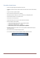
Introduction RF Explorer has been designed to be intuitive and easy to use. There is no need to read large user manuals to get advantage of its advanced functionality. Most of the complexity inherent to full sized Spectrum Analyzers is simplified with automatic functionality resolved by the firmware. For instance, you do not need to adjust Resolution Bandwidth (RBW) everytime you select a different frequency span. Actually, you do not even need to know what RBW is.
Description of main features Pocket size and light weight with solid aluminum metal case. The Spectrum Analyzer calculator includes Peak Max, Max Hold, Normal, Overwrite and Averaging modes. Lifetime free firmware upgrades available. Open to new features requested by user community. High capacity Lithium Ion battery up to 16hs of continuous run, rechargeable by USB. Microsoft Windows software is free and Open Source. Mac OS client is free and Open Source.
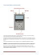
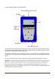
Connecting RF Explorer Standard model The RF Explorer Standard models includes 7 functional buttons in the front side. The unit also includes at least one RF connector 50 ohm impedance standard SMA format. All models have a SMA left connector installed and, optionally, some models have a second SMA connector at the right position for extended range and functionality. For more details see the section Expansion Modules in page 31.
Connecting RF Explorer Plus model The RF Explorer Plus models includes 9 functional buttons in the front side, including context sensitive HELP and easy preset handling with SET button, and a silicone rubber protector. The unit also includes at least one RF connector 50 ohm impedance standard SMA format. All models have a SMA left connector installed and, optionally, some models have a second SMA connector at the right position for extended range and functionality.
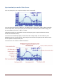
Spectrum Analyzer mode - Main Screen Upon start, RF Explorer goes to Spectrum Analyzer mode automatically. The X axis represents frequency in MHZ and Y axis display actual received power in dBm or dBuV (selectable). In this example above, the frequency span goes from 2390 MHz to 2450 MHz (that is a 60MHz range), and the visual amplitude goes from -1 dBm to -110 dBm. Configuration settings such as amplitude reference and frequency span are preserved between sessions, stored in internal FLASH memory.
The available indicators are: USB / battery status: this indicator will display USB1 when a valid 5V USB connection is available. This will be true even if the connection is through a wall wart charger, so it does not actually means a data connection but a power bus connection. Alternatively, a battery icon with charge level indicator will display when the RF Explorer unit power switch is set to ON.
Using menus There are several menus in RF Explorer. They are organized on different screens, which you can iterate through by using the [Menu] key. If you click [Menu] button multiple times, you will visit every one of them: Optionally, you can use the [Left] and [Right] keys to go from one screen to another. You can exit from a menu anytime by using the [Return] key. The first time you click on [Menu] button in a RF Explorer session, Frequency Menu will open.
actually re-open the last menu you were working with. In this way you save time by not having to navigate through all the menus to go the same place you were before.
Operational Mode menu The menu display different functional modes available in your Analyzer. Use [Up] and [Down] arrow keys to select the desired mode and click on [Enter] to activate it immediately. Spectrum Analyzer mode is the default mode, available in all RF Explorer models RF Generator option is available in some models only. These include models ISM Combo, 2.4G, 433M, 868M and 915M, other models do not have internal RF Generator circuit.
About displays information about installed firmware and versioning. Use any key to get out of this screen.
Frequency Menu Center Freq: Center frequency in MHZ Freq Span: Frequency span (or range) to display on screen in MHZ Start Freq: Lower frequency range to display on screen in MHZ Stop Freq: Higher frequency range to display on screen in MHZ Module: Active selected RF module. When an expansion module is installed, click [Enter] key to enable the module you need.
As an example, a center frequency of 430MHz with a 20MHz span: A click on [Menu] button will open the Frequency Menu: Selecting a span of 10MHz, the Start/Stop frequency changes accordingly: A click on [Return] button will close the menu and go back to Spectrum Analyzer main screen.
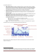
Analyzer screen in Advanced Mode Alternatively, there is a simpler way to increase and decrease frequency span while keeping the center frequency. As this is a usual workflow, the RF Explorer Spectrum Analyzer screen enables the [Return] key to switch between standard visualization mode and advanced mode. In this screen above, the frequency reading at the bottom changed from Start/Center/Stop frequency to Span/Center/RBW.
To put it simple: Selecting the best combination of RBW, scan speed and sensitivity requires significant experience. In most Spectrum Analyzers, operator needs to fully understand and select RBW for each measurement, being this one of the most challenging aspects of proper Spectrum Analyzer usage. Fortunately, this is not the case with RF Explorer: The design of the internal DSP includes sophisticated internal tables and algorithms to make the best possible choice at all times automatically.
Attenuator Menu Calculator: internal DSP calculator mode. Input: select input stage to enable LNA or Attenuator - only in PLUS models Top dBm: Visual max amplitude on screen. Bottom dBm: Visual min amplitude on screen. Iterations: Internal DSP calculator iterations. Offset dB: external dB attenuation or gain value to compensate for external devices, such as attenuators or amplifiers. Units: dBm or dBuV.
by 5dBm each time. This shortcut, together with [Left] and [Right] for moving Center Frequency or Span as described before, are very convenient to make configuration changes real-time with no need to visit the Menu.
Configuration Menu Backlight: Several levels of display backlight. RF Explorer has good visibility indoor and outdoor, including direct sunlight. The level of backlight should be the appropriate for each condition, and you may want to limit backlight brightness to preserve battery capacity. Contrast: There are 10 different display contrast levels to choose from. USB Bauds: Default is 500Kbps, which is also the recommended setting.
Preset Menu Preset is a convenient facility to store multiple configurations which can be easily recovered. This feature is supported in selected models only: RF Explorer Combo models (since firmware v1.26) and RF Explorer Plus models. Identifier: Numerical index of the preset valid from 1-100 (Plus model) or 1-30 (Combo models) Description: Descriptive text up to 12 characters long. An asterisk at the end is automatically added when the preset has actually some data stored.
Using RF Explorer Preset Manager This is an included convenient tool to easily create and edit Presets from a Windows, Linux or Mac computer. It also includes the ability to define custom Description text for each preset. Presets can be uploaded to / downloaded from the RF Explorer device using USB standard connection, and presets definitions can be imported / exported to share definition among devices easily. For more details please visit online help: http://www.rf-explorer.
HELP button (Plus model only) RF Explorer WSUB1G Plus model includes HELP button for easy, intuitive context-sensitive help. The HELP text can be displayed in all functional screens, effectively complementing this User Manual with handy information, always available with a simple click. Use the following keys to interact with Help screen: Scroll text up and down: The bottom of screen shows “…” when additional text is available for scroll.
RF Generator mode Some RF Explorer models can generate a CW RF tone or a configurable sweep for testing RF receivers and simulating interference very easily. Frequency: Transmit frequency in MHZ in single tone mode, or start frequency in MHZ in sweep mode. Power: Transmit power in dBm, increasingly changed by 3dB steps each time [Enter] key is pressed. Accuracy is typically +-3dB and can be significantly influenced by the matching load.
IMPORTANT You must have connected a 50 ohm antenna or RF load before you switch your transmitter ON. If you switch the transmitter ON without a proper antenna, you may damage the RF module of your RF Explorer, as the power amplifier will not have a load to feed. Think of the equivalent to an audio amplifier running at full power with no speakers connected: you are likely damaging the power transistors. You can use any kind of RF 50 ohm load, including a dummy load, a coaxial with a 50 ohm termination, etc.
RF Explorer internal battery The internal battery is a high capacity Lithium-ion polymer 1000mAh. This is the same battery technology used in cell phones and modern laptops and tablet computers. The power switch is a true hard switch connecting the battery in ON position, fully isolating the battery in the OFF position.
It is ok having the battery connected forever to the USB port, the internal charger will stop and start the charge when needed. If your USB port is unpowered it may not be capable of delivering more than 100mA; the battery may not be charged at all. If you have no other option available than a 100mA USB port, set the LCD backlight to OFF in the OPTIONS MENU and keep charging for as long as needed (it may take up to 24hs in these conditions so you should use a powered USB port whenever possible).
overnight. Note: for the sake of clarity, below black/white screen images are depicted when LCD backlight is OFF. In this mode you can stop charging whenever the device reaches 99% or 100%, which may take up to 2 or 3 hours under normal condition and depending on initial battery charge level. When the charging algorithm detects the battery fully charged and a minimum of 2hs connected, it will suggest disconnecting the USB cable.
After the device recalibrates the internal battery charge reference level, it will automatically restart and you should see the Battery icon (on Spectrum Analyzer screen) showing full charge. Charging a fully depleted battery The firmware includes a protection mechanism to shutdown everything if the battery goes too low, in the range of 3.3V or less. However, this state will still keep drawing about 1mA from the battery.
Expansion Modules RF Explorer includes an internal expansion port to enhance the capabilities and frequency coverage of the main unit with RF Explorer compatible Expansion Modules. To learn more about different expansion options available for your unit, please visit www.rf-explorer.com/models Assembling an expansion module is very easy task; see step by step details at www.rf-explorer.
RF Explorer antennas RF Explorer includes one antenna for narrow band models, and two antennas for WSUB1G Plus, ISM Combo, 3G Combo and Wifi Combo models. The antennas are selected for its versatility, and they offer reasonable response over the applicable band. However, certain applications and uses may require additional antennas to be purchased separately, such as directional high gain antennas, narrow band antennas for a specific band, etc.
The RF Explorer WSUB1G Plus includes two antennas described below: Gray articulated antenna is UHF antenna described in section UHF antenna. Black telescopic antenna is NA-773 described in section Nagoya Telescopic NA-773. Nagoya Telescopic NA-773 This is a telescopic, high quality 2dBi antenna ideally suited for 144MHz and 430MHz bands, typically used in two way radios and HAM bands. It offers a good response in all frequencies below 1GHz.
RF Explorer 915M: includes a 2dBi antenna tuned for 915MHz RF Explorer 2.4G: includes a 2dBi antenna tuned for 2450MHz RF Explorer ISM Combo and 3G Combo: In addition to the NA-773, the Combo models include a 2dBi antenna tuned for 2450MHz. Rubber duck 5.8GHz antenna This is a quality antenna with good coverage in the range of 5.4-5.9GHz. It offers reasonable coverage in the 2.4 Ghz band too, so can be used as dual band antenna for WiFi. This antenna is included in RF Explorer 6G, 6G Combo and Wifi Combo.
Additional antennas As a general purpose RF Spectrum Analyzer, RF Explorer can be used to measure and diagnose different frequency bands. For physical reasons, there is no antenna design which can effectively work at all possible frequencies, therefore we provide additional antenna choices based on required band. Any 50ohm antenna can be connected to RF Explorer, but we selected, tested and validated a few convenient quality antennas as listed below.
Cloverleaf dual band 2.4 / 5.8Ghz omnidirectional The CloverLeaf omnidirectional antenna is the perfect choice to use RF Explorer in 2.4Ghz and 5.8GHz bands. CloverLeaf antennas have circular polarization and therefore can detect all direct and bouncing signals, making a way superior choice to detect interference and wanted radiations.
Protecting your instrument from damage RF Explorer is a very sensitive device. It can detect signals as low as -120dBm, which is 10E-12mW or 9nA over a 50ohm load. This extreme sensitivity comes at the price of some fragility; your device needs care handling and protection in order to run for many years without problems. Most RF technicians know the RF instruments have to be protected in order to survive the high Electro Magnetic (EM) fields that may be in the environment.
As an example, the RF Explorer WSUB1G -with a frequency range of 240-960MHz- will not detect a microwave oven (2.4GHz) on the screen but can be very well damaged by it. Similarly, a strong 2m HAM or FM high power transmit station won’t be detected by this model, but still induces enough RF power to kill the RF circuitry with ease.
RF Explorer Power Limiter The RF Explorer Power Limiter is a custom device designed from scratch to be the perfect protection against strong RF fields. All RF Explorer models have some power ranges for input signal beyond which can be damaged. For some models, the limit is on +5dBm, some others are ok up to +10dBm but only 6G, 6G Combo, and the RF SMA connector on the right side in a 3G Combo are protected up to +30dBm. See the table in page 37 for more details.
The Power Limiter is assembled in a rugged aluminum case and it is very compact when compared to other market offerings, not to mention it includes internal DC block and attenuator which makes it a really small device for what it offers. It is a recommended add-on to all users who may expose their unit to strong external fields.
RF Explorer Holder This is a great accessory for the RF Explorer, a high quality stand / holder for the desk while USB cable is connected. The holder is made of robust laser cut blue acrylic and has provisioned room for a USB cable to connect to a PC. The USB cable can be connected from behind the holder or any of the two lateral large holes on each side. They're even large enough for bulky USB cables with ferrite beads.
RF Explorer Near Field antennas The RF Explorer Near Field Antenna Kit is a set of 4 high performance antennas designed for the most demanding RF diagnosis tasks: RFEAH-25 – H-Loop magnetic 25mm diameter RFEAH-15 – H-Loop magnetic 15mm diameter RFEAH-5 – H-Loop magnetic 5mm diameter RFEAE-10 – E-Field stub 10mm length The low loss design of these antennas exhibits at least 10dB more sensitivity than other near field antennas in the market, at a much lower cost.
Magnetic H-Loop antennas There are three different magnetic antenna options: As the antenna diameter gets shorter, the spatial resolution increases at the cost of some sensitivity loss at low frequencies, but best response at high frequencies; you should select RFEAH-25 for best sensitivity with connectors, large ICs and isolated signal traces, whereas RFEAH-5 works best for very narrow selective work in a populated PCB with close-by signal traces. RFEAH-15 is a good in-between compromise.
RF Explorer accessories RF Explorer uses standard SMA quality connectors. By using adapters you can connect RF Explorer to any RF device or antenna. You can buy SMA adapters and devices on any RF shop, but sometimes is difficult to find what you need and have the certainty the connector you are ordering is the right one. Therefore we have included a selection of quality connectors, adapters and RF devices that are fully compatible with RF Explorer.
RF Adapter RP-SMA Jack to SMA Plug straight-long version Some WiFi antennas and cables are designed for RP-SMA (reverse polarity SMA) and cannot be connected to a standard SMA plug. RP-SMA is a variation of the SMA connector specification which reverses the gender of the interface. The reason for that was a decision made by FCC in order to prevent end-users from manipulating certified WiFi devices at home, using other available SMA antennas.
SMA connection cables RF cables are an important tool required to directly connect your Spectrum Analyzer to another device (such as a RF transmitter or an antenna) or with a Signal Generator for tracking. Cables add attenuation to your measurement and, if not correctly connected or if the cable is low quality, it may largely invalidate any measurement.
50cm length - SMA male to SMA female RF pigtail Coaxial Cable RG316 RF cables are required when connecting RF Explorer to other instruments or devices. This 50cm cable is good for any frequency up to 3GHz, and can fit RF Explorer with any external SMA-male device or antenna. If you need extra length for your connection, you can easily daisy chain two or more of these cables in series.
Attenuators SMA attenuators are used to reduce the input power, and therefore enable RF Explorer to measure stronger signals. It is also used to protect the input SMA port of RF Explorer when unknown strong signals may be in the environment, so you can use this attenuator on demand. You can easily unplug the attenuator when measurement is for weak signals. You can also combine multiple attenuators to get additional values.
6GHz SMA Attenuator - 10dB This precision attenuator can measure up to 6GHz frequency range with high amplitude accuracy. Use OffsetDB: +010 when connected to this attenuator. 6GHz SMA Attenuator - 30dB This precision attenuator can measure up to 6GHz frequency range with high amplitude accuracy. Use OffsetDB: +030 when connected to this attenuator.
SMA Male/Female Adaptor All RF connectors wear with use. The RF Explorer SMA ports are subject to minimal wear each time the connector interface is coupled and decoupled with an antenna, a SMA cable, an attenuator or a RF device of any kind. If you repeat plug/unplug operations over the RF Explorer SMA port hundreds of times, the SMA port may underperform over time and exhibit undesired attenuation.
Connecting RF Explorer to a computer RF Explorer device can be connected to a computer (Windows, Linux, Mac and Android) for additional capabilities, including higher resolution screen, additional features and programmability. For free, open source RF Explorer for Windows tool, please check this link: www.rf-explorer.com/windows For additional software options developed by a growing list of 3rd party companies, please check this link: www.rf-explorer.
Specifications For a complete list of features and RF Explorer models, expansion boards available, and accessories please check the RF Explorer Model Map online. www.rf-explorer.com/models Acknowledgments This product could not be possible without the SeeedStudio Team who manufacture, test and distribute RF Explorer worldwide. RF Explorer is a reality thanks to the great community behind, always suggesting features and providing useful feedback.