2ND PRINTING DEC 99 STD VERSION OWNER’S MANUAL SEGA ENTERPRISES, INC. USA MANUAL NO.
Warranty Your new Sega Product is covered for a period of 90 days from the date of shipment. This certifies that the Printed Circuit Boards, Power Supplies and Monitor are to be free of defects in workmanship or materials under normal operating conditions. This also certifies that all Interactive Control Assemblies are to be free from defects in workmanship and materials under normal operating conditions. No other product in this machine is hereby covered.
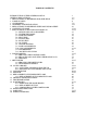
TABLE OF CONTENTS INTRODUCTION OF THE OWNERS MANUAL GENERAL PRECAUTIONS 1. PRECAUTIONS TO BE HEEDED FOR OPERATION 2. NAME OF PARTS 3. ACCESSORIES 4. ASSEMBLY AND INSTALLATION 5. PRECAUTIONS TO BE HEEDED WHEN MOVING MACHINE 6. CONTENTS OF GAME 7. EXPLANATION OF TEST AND DATA DISPLAY 7-1 SWITCH UNIT AND COIN METER 7-2 SYSTEM TEST MODE 7-3 GAME TEST MODE 7-4 INPUT TEST 7-5 OUTPUT TEST 7-6 SOUND TEST 7-7 C.R.T.
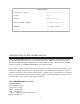
SPECIFICATIONS Installation space: 68 in.(L) x 41 in.(W) Height: 84 in. Weight: Approx. 550 lbs. Power maximum current: 3.5 Amp AC 120V 60 Hz MONITOR: 29” NANAO MONITOR INTRODUCTION OF THE OWNERS MANUAL SEGA ENTERPRISES, LTD., has for more than 30 years been supplying various innovative and popular amusement products to the world market.
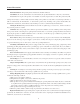
General Precautions Follow Instructions: All operating and use instructions should be followed. Attachments: Do not use attachments not recommended by the product manufacturer as they may cause hazards. Accessories: Do not place this product on an unstable cart, stand, tripod, bracket, or table. The product may fall, causing serious injury to a child or adult, and serious damage to the product. Use only with a cart, stand, tripod, bracket, or table recommended by the manufacturer, or sold with the product.
Safety Check: Upon completion of any service or repairs to this product, ask the service technician to perform safety checks to determine that the product is in proper operating condition. Heat: The product should be situated away from heat sources such as radiators, heat registers, stoves, or other products (including amplifiers) that produce heat. Lithium Battery y- Dispose of batteries only in accordance with the battery manufacturer’s recommendations.
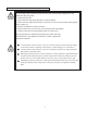
1 . PRECAUTIONS TO BE HEEDED FOR OPERATION In order to prevent accidents, be sure to comply with the following points before and during operation. PRECAUTIONS TO BE HEEDED FOR OPERATION BEFORE STARTING THE OPERATION In order to avoid accidents, check the following before starting the operation: Check if all of the adjusters are in contact with the surface. If they are not, the cabinet can move and cause an accident. Do not climb on the product. Climbing on the product can cause falling down accidents.
PRECAUTIONS TO BE HEEDED DURING OPERATION To avoid injury and accidents, those who fall under the following catagories are not allowed to play the game: * Intoxicated persons * Those who have high blood pressure or heart problems. * Those who have experienced muscle convulsion or loss of consciousness when playing video games, etc. * Persons susceptible to motion sickness. * Persons whose acts runs counter to the products warning displays.
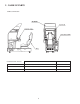
2 . NAME OF PARTS JAMBO SAFARI STD GAME SPECIFICATIONS WIDTH in. LENGTH in. HEIGHT in. WEIGHT lbs. All measurements are and rounded UP DURING SHIPPING 45” X 70” X 84” ~ 600 LBS. WHEN ASSEMBLED 39” X 65” X 80” 550 LBS.
3 .
THE SHIPMENT METHOD DESCRIBED BELOW ONLY APPLIES TO ‘MODEL 3’ BOARDS CONTAINED IN THE FOLLOWING GAMES: LOST WORLD, VIRTUA FIGHTER 3, SUPER GT, SEGA BASS FISHING, STRIKER 2 HARLEY DAVIDSON, RALLY 2, DAYTONA 2, DIRT DEVILS, HOUSE OF THE DEAD 2, OCEAN HUNTER, STAR WARS TRILOGY, ZOMBIE REVENGE, CRAZY TAXI, MAJOR LEAGUE BASEBALL, VIRTUA TENNIS, JAMBO SAFARI !!NEVER SHIP MODEL 3 / NAOMI GAME BOARDS OUTSIDE OF CAGE!! CARTON BOX 601-8928 (1) Used for transporting the GAME BOARD.
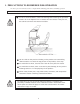
4 . ASSEMBLING AND INSTALLATION Assembling should be performed as per this manual. Since this is a complex machine, erroneous assembling may cause damage to the machine, or malfunctioning to occur. When assembling, be sure to perform work by plural persons. Depending on the assembly work, there are some cases in which performing the work by a single person can cause personal injury or parts damage.
1 Install the coin chute tower on the Right-hand side of cabinet. Open the coin chute door and the cashbox door to secure with the 4 hexagon bolts from inside the doors. Please note that the Coin Chute tower is NOT mounted on the Left-hand side as shown above. NOTE: ON SEGA’s CRAZY TAXI GAME THERE IS NOT TWO COCKPITS SIDE BY SIDE AS PICTURED ABOVE. THE GAME HAS ONLY ONE COCKPIT AND THE COIN TOWER WILL MOUNT ON THE RIGHT SIDE AS YOU FACE THE CABINET..
2 ASSY OF THE BILLBOARD Due to its large size, it is very difficult for one person alone to install the billboard, Make sure 2 or more persons are available to perform this work. Attempting to perform the installation alone can cause an accident. 1 Mount Billboard on cabinet by ensuring the front lip of the Billboard is securely placed under the mounting bracket already installed on the cabinet. Fasten with the 3 hexagon bolts.
3 SECURING IN PLACE (ADJUSTER ADJUSTMENT) Be sure to have all the Adjusters make contact with the surface. Unless the Adjusters come into contact with the surface, the Cabinet can move of itself, causing an accident. This machine has 4 each of casters and adjusters (shown below). When the installation position is determined, cause the adjusters to come into contact with the floor directly, make adjustments in a manner so that the casters will be raised approximately 5mm.
4 POWER SUPPLY Ensure that the power cord is not exposed on the surface (passage, etc.). If exposed, they can be caught and are susceptible to damage. If damaged, the cord can cause an electric shock or short circuit. Ensure that the wiring position is not in the customer's passage way or the wiring has protective covering. Connect the game to the power supply and turn on power to the game.
5 ASSEMBLING CHECK The TEST MENU allows for each part of the cabinet to be checked, the Monitor to be adjusted, and the coin and game related various functions to be performed. Selecting the MEMORY TEST on the test mode menu screen causes the on-board memory to be tested automatically. The game board is satisfactory if the display beside each IC No. shows GOOD. Selecting the INPUT TEST on the Test Mode menu screen causes the screen (on Which each switch adnV.R. are tested) to be displayed.
SOUND TEST VOICE EFFECT B.G.M. In the TEST mode, selecting SOUND TEST causes the screen, on which sound related BD and wiring connections are tested, to be displayed. Be sure to check if the sound is satisfactorily emitted from each of speaker and the sound volume is appropriate. >EXIT SELECT WITH SERVICE BUTTON AND PRESS TEST BUTTON TO EXIT C.R.T.
5 . PRECATIONS TO BE HEEDED WHEN MOVING THE MACHINE When moving the machine, be sure to pull out the plug from the power supply. Moving the machine with the plug as is inserted can damage the power cord and cause a fire or electric shock. When moving the machine on the floor, retract the Adjusters and ensure that Casters make contact with the floor. During transportation, pay careful attention so that Casters do not tread power cords.
6 . CONTENTS OF GAME The following explanations apply to the case the product is functioning satisfactorily. Should there be any moves different from the following contents, some sort of faults may have occured. Immediately look into the cause of the fault and eliminate the cause thereof to ensure satisfactory operation. During the Advertise mode, the Billboard’s Decoration Lamp lights up periodically. When the machine is energized, the Billboard’s Fluorescent Lamp is always lit.
HOW TO PLAY 1 Insert a coin. Coin insertion causes credit(s) to be displayed on the screen. For example, in the case of 2 coins one credits setting, “INSERT MORE COIN(S) CREDIT(S) 1/2” is displayed when one coin is inserted. 2 Inserting one play worht of coin(s) causes “PRESS START BUTTON” to be displayed and START button to flash. Press START button to have the Mode Select Screen appear on the monitor. 3 Select the play mode from either BEGINNER or EXPERT Mode in the Mode Select Screen.
6 When the rope is passed around the animal, pull the rope by inclingin the Lever towards you and approach the animal. Time is increased by at least onesecond each time the player get s the ring attached to the rope. When the rope flashes red and the tension gauge displays “ATTENTION”, release the Lever to loosen the rope. Otherwise the rope will be broken. 7 Throw the net over the animal. When the player’s view changes and the screen displays the sight, throw the net by inclining the Lever backward.
9 Upon completion of the Evaluation Mode, the monitor shifts to the Binoculars Mode. In the Binoculars Mode, various kinds of animals around the player and the distance to the animals are shown. In this mode, when the Steering Wheel is turned, the view point is also shifted to the same direction. Step on the Accelerator pedal whe the animal aimed at appears, and the screen shifts to the Searching for animals mode from thr Binoculars Mode and displays the arrow pointing to the animal on the ground.
KNACK OF PLAY 1 Always keep the animal on the center of the screen when drawing in the rope. If you operate the Steering Wheel keeping the this in mind, you can smoothly get close to the animal. 2 Don’t chase the animal too far. If it seems to take too much time to ge the animal you aim at, change to the animal of lower rank. Know your technical level and pay attention to the time. 3 Use Commands. DASH: With the Steering Wheel in the centering position, quickly step on the Accelerator pedal twice.
7 . EXPLANATION OF TEST AND DATA DISPLAY By operating the switch unit, periodically perform the tests and data check. When installing the machine initially or collecting cash, or when the machine does not function correctly, perform checking in accordance with the explanations given in this section. The following shows tests and modes that should be utilized as applicable.
7 - 1 SWITCH UNIT AND COIN METER Never touch places other than those specified. Touching places not specified can cause electric shock and short circuit. Adjust to the optimum sound volume by considering the environmental requirements of the installation location. If the COIN METER and the game board are electrically disconnected, game play is not possible. Open COIN CHUTE DOOR, and the switch unit shown appears.
7 - 2 SYSTEM TEST MODE The contents of setings chnaged in the TEST mode are stored when the TEST mode is finished from EXIT in the MENU mode. If the power is turned off before the TEST mode is finished, the contents of setting chnage become ineffective. Executing “BACKUP DATA CLEAR” in the SYSTEM TEST MODE does not clear the BOOKKEEPING data in the GAME TEST MODE. Entering the TEST mode clears fractional number of coins less than one credit and BONUS ADDER data.
7 -4 INPUT TEST Select INPUT TEST to have the screen shown below appear and to observe the status of each switch and the value of each V.R. on the Control Panel. Periodically check the status of each switch and V.R. on this screen. INPUT TEST COIN CHUTE #1 COIN CHUTE #2 SERVICE TEST START LEVER UP LEVER DOWN HANDLE ACCEL BRAKE OFF OFF OFF OFF OFF OFF OFF 7bH 3fH 33H PRESS TEST AND SERVICE BUTTON TO EXIT FIG. 7.
7 - 6 SOUND TEST SOUND TEST B.G.M: 0/47 (SOUND STOP) 0/360 (SOUND STOP) 0/7 (SOUND STOP) EFFECT: ICS: >EXIT This test mode allows each sound related board and speaker to be checked. Press the Service Button to select the sound to be tested, and press the Test Button to have the selected Sound Test screen appear. Select EXIT and press the Test Button to return to the Test Menu. SELECT WITH SERVICE BUTTON PRESS TEST BUTTON TO EXIT FIG. 7.6 SOUND TEST 7 - 7 C.R.T. TEST C.R.T.
7 - 8 VOLUME SETTING When VOLUME SETTING is selected, the following appears on the screen and each operating unit’s Volume can be set. If the operability is unsatisfactory, or when the Volume is adjusted or replaced, set the Volume in this mode. The 3 kinds of Volume Settings for HANDLE, ACCEL, and BRAKE are to be set. The Max. value, Min. value for each and the HANDLE’S CENTER value are to be set as applicable.
7 - 9 GAME ASSIGNMENTS Selecting the GAME ASSIGNMENTS in the MENU mode causes the present game settings to be displayed and also the game settings changes (game difficulty, etc.) can be made. Each item displays the following content. SETTING CHANGE PROCEDURE 1 2 3 Press the SERVICE BUTTON to move the “>” to the desired item. Choose the desired setting change item by using the TEST BUTTON. To return to the MENU mode, move the arrow to EXIT and press the TEST BUTTON.
7 - 10 COIN ASSIGNMENTS The “COIN ASSIGNMENTS” mode permits you to set the start number of credits, as well as the basic numbers of coins and credits. This mode expresses “how many coins correspond to how many credits.” SETTING CHANGE PROCEDURE Setting changes cannot be stored unless the TEST BUTTON is pressed while the arrow is on EXIT. 1 Press the SERVICE BUTTON to move the arrow to the desired item. 2 Choose the desired setting change item by using the TEST BUTTON.
TABLE 7.
MANUAL SETTING Selecting MANUAL SETTING in the COIN ASSIGNMENTS mode displays the following screen. MANUAL SETTING COIN TO CREDIT 1 COIN BONUS ADDER NO BONUS ADDER 1 1 CREDIT 2 COIN CHUTE #1 MULTIPLIER 1 COIN COUNTS AS 1 COIN COIN 1 2 3 CREDIT 1 2 3 4 4 5 5 6 6 7 7 8 8 9 9 COIN CHUTE #2 MULTIPLIER 1 COIN COUNTS AS 1 COIN COIN 1 2 3 CREDIT 1 2 3 4 4 5 5 6 6 7 7 8 8 9 9 3 >EXIT SELECT WITH SERVICE BUTTON AND PRESS TEST BUTTON FIG. 7.11b MANUAL SETTING 1 Determines Coin/Credit setting.
7 - 11 BOOKKEEPING Choosing BOOKKEEPING in the MENU mode displays the data of operating status up to the present are shown on 2 pages. Press the TEST BUTTON to proceed to PAGE 2/2. BOOKKEEPING NUMBER OF GAMES Total number of plays. PAGE1/3 NUMBER OF CONTINUE Total number of continues. NUMBER OF GAMES NUMBER OF CONTINUE AVERAGE PLAY TIME 0 0 00H 00M 00S In Page 2/3, Histogram of Number of Play as against Play Time is displayed. For setting the DIFFICULTY, refer to this histogram.
8. HANDLE MECHA In order to prevent an electric shock and short circuit, be sure to turn power off before performing work by touching the interior parts of the product. Be careful so as not to damage wirings. Damaged wiring can cause an electric shock or short circuit accident. In the test mode, if the steering wheel’s VR variations are not within the allowable range, the VR installation position adjustments or VR replacement is needed.
8 - 2 REPLACING AND ADJUSTING THE HANDLE’S VR Never touch places other than those specified. Touching places not specified can cause electric shock and/or short circuit. After the replacement or adjustment of the VR, be sure to set the variable value of the VR in the test mode’s Volume Setting. REPLACING THE VOLUME 1 Turn off the power. 2 Disconnect the connector. 3 Take out the 2 screws which secure the volume Bracket and remove the Volume Bracket.
8 - 3 GREASING Never touch places other than those specified. Touching places not specified can cause electric shock and/or short circuit. After the replacement or adjustment of the VR, be sure to set the variable value of the VR in the test mode’s Volume Setting. Apply greasing to the Volume gear mesh portion every 3 months. For spray greasing, use Grease Mate (Part No. 090-0066).
9. SHIFT LEVER In order to prevent electric shock and short circuit, be sure to turn off the power before performing work on the interior parts of the product. Be careful not to damage wiring. Damaged wiring can cause electric shock or short circuit. Do not touch places other than those specified. Touching places other than those specified can cause an electric shock or short circuit accident.
9 - 2 SWITCH REPLACEMENT Each microswitch is secured with 2 screws. Remove the 2 screws and replace the Microswitch. After replacing the Switch, check to see if the switch is inputted as per Shift Lever operation in the Test Mode.
10. ACCEL & BRAKE(S) In order to prevent an electric shock and short circuit, be sure to turn power off before performing work by touching the interior parts of the product. Be careful so as not to damage wirings. Damaged wiring can cause an electric shock or short circuit accident. Do not touch places other than those specified. Touching places not specified can cause an electric shock or short circuit accident.
Check Volume values in the Test Mode. Since work is performed inside the energized cabinet, be very careful so as not to touch undesignated portions. Touching places not specified can cause an electric shock or short circuit. 1 Take out the 2 truss screws and remove the Front Cover from the Accel. & Brake unit. 2 Loosen the screw which secures the Potentiobase, and adjust the Volume Value by moving the Base. 3 Secure the Potentiobase. 4 Perform Volume setting in the Volume Setting Mode.
11 . COIN SELECTOR HANDLING THE COIN JAM If the coin is not rejected when the REJECT BUTTON is pressed, open the coin chute door and open the selector gate. After removing the jammed coin, put a normal coin in and check to see that the selector correctly functions. CLEANING THE COIN SELECTOR 1 2 3 4 5 6 GATE The coin selector should be cleaned once every 3 months. When cleaning, follow the procedure below: Turn the power for the machine OFF. Open the coin chute door.
OPTIONAL DOLLAR BILL ACCEPTOR THE COIN DOOR ASSEMBLY USED ON JAMBO SAFARI COMES EQUIPPED TO ACCEPT A DOLLAR BILL ACCEPTOR. ALL NEEDED WIRING CONNECTIONS ARE CONVIENENTLY LOCATED INSIDE THE GAME FOR THIS APPLICATION. THE COIN DOOR CAN ACCCOMMODATE THE FOLLOWING VALIDATORS: HOLE POSITION#1 (FORWARD-MOST POSITION) Mars 2000 series HOLE POSITION#2 Mars 2000 series DBV45 (JCM) HOLE POSITION #3 CURRENTLY NOT USED HOLE POSITION #4 DSI01* *The back flange on the chute can be removed for hold position #4.
42
12. MONITOR When performing such work as installing and removing the monitor, inserting and disconnecting the external connectors to and from monitor, be sure to disconnect the power connector (plug) before starting work. Proceeding the work without following this instruction can cause electric shock of malfunctioning. Using the monitor by converting it without obtaining a prior permission is not allowed. SEGA shall not be liable for any malfunctioning and accident caused by said conversion.
For the purpose of static prevention, special coating is applied to the CRT face of this product. To protect the coating, pay attention to the following points. Damaging the coating film can cause electric shock to the customers. For the caution to be heeded when clearing, refer to the Section of Periodic inspection Table. Do not apply or rub with a hard item (a rod with pointed edge, pen, etc.) to or on C.R.T. surfaces. Avoid applying stickers, seals, etc. on the C.R.T. face.
45
13. REPLACEMENT OF FLUORESCENT LAMP When performing the work, be sure to turn power off. Working with power on can cause an electric shock or short circuit accident. The Fluorescent Lamp, when it gets hot, can cause burns. Be very careful when replacing the Fluorescent Lamp. To perform work safely and securely, be sure to prepare a step which is in a secure and stable condition. Not using a step or using an unstable step can cause violent falling down accidents.
14. PERIODIC INSPECTION TABLE The items listed below require periodic check and maintenance to retain the performance of this machine and ensure safe operation. Be sure to check once a year to see if Power Cords are damaged, the plug is securley inserted, dust is accumulated between the Socket Outlet and the Power Plug, etc. Using the product with dust as is accumulated can cause a fire or electrical shock. Periodically once a year, request the place of contact herin stated or the Distributer, etc.
15. TROUBLESHOOTING Should trouble occur, first check connector connections. PROBLEMS CAUSE COUNTERMEASURES With Main SW ON, no activation Power is not supplied. Plug in correctly Power supply/voltage is not correct. Make sure that power supply/voltage is correct. Check fuse. Remove the cause of overload and replace fuse AC main fuse causes the power to be cut off due to momentary overload. Operation is unsatisfactory Volume Setting Failure Perform Volume setting Adjust or replace V.R.
16. GAME BOARD In order to prevent an electrical shock, be sure to turn power off before performing work by touching the interior parts of the product. Be careful so as not to damage wirings. Damaged wiring can cause an electric shock or short circuit accident. Do not expose the Game BD, etc. without a good reason. In this product, setting changes are made during the test mode. The Game BD need not be operated. Use the Game BD, etc. as is with the same setting made at the time of shipment.
16 - 2 REPLACEMENT OF FUSE In order to prevent an electric shock, be sure to turn power off before performing work by touching the interior parts of the product. Be careful so as not to damage wirings. Damaged wiring can cause an electric shock or short circiut accident After eliminating the cause of the blowing of fuse, replace the fuse. Depending on the cause of the fuse blowing, using the fuse as is blown can cause generation of heat resulting in fire.
16 - 3 COMPOSITION OF GAME BOARD Ensure that the DIP SW setting is performed as designated as designated. Failure to observe thisw may cause functioning not suitable for tyhe operation, or malfunctioning. ASSY CASE NAO USA (840-0002D-01) :USA DIP SW SETTING IN the product, set all of the DIP SWes to OFF.
17. DESIGN RELATED PARTS ITEM NO. PART NO.
18. PARTS LIST TOP ASSY JAMBO SAFARI STD ITEM NO. PART NO.
ASSY BILLBOARD STDJBA (999-0887) ITEM NO. PART NO.
ASSY COINCHUTE TOWER (DUT5-0300) 55
ASSY COINCHUTE TOWER (DUT5-0300) ITEM NO. PART NO. DESCRIPTION 1 2 3 4 5 10 11 12 13 101 102 103 104 105 106 SPG1-0350 SPG1-0301 DYN-0302Y DP-1167 BOX-CASH DYN-0305 105-5202 SPG-0302 SPG-0303 92-1003-05* 220-5412 999-0169 220-5574 220-5575 999-0167 SW UNIT COIN CHUTE TOWER COIN METER BRKT TNG LKG CASH BOX TOWER BRKT HOLE COVER WIRE BOX WIRE BOX LID ASSY C.C.
SW UNIT (SPG5-0350) ITEM NO. PART NO.
AC UNIT (DRT1-0400) TEM NO. PART NO. DESCRIPTION 1 101 102 105 SPG5-0401 600-5843-25 280-5134-6N34 509-5453-91-V-B AC BRKT CA & PLUG ASSY 15A W/F-L=2.
ASSY SPEAKER (SPG-1100) ITEM NO. PART NO.
ASSY VIRTUAL BUTTON TWIN (DRT5-1290) ITEM NO. PART NO.
ASSY BASE BOX (DRT1-1500) ITEM NO. PART NO.
MAIN BASE (DRT1-1501) ITEM NO. PART NO.
ASSY SEAT TWIN 1P (DRT-1600) 63
ASSY SEAT TWIN 1P (DRT1-1600) ITEM NO. PART NO.
ASSY WOOFER (STC-1650) ITEM NO. PART NO.
ASSY ACCEL&BRAKE (SPG-2200) 66
ASSY ACCEL&BRAKE (SPG-2200) ITEM NO. PART NO.
ASSY HANDLE MECHA (CTA-2100) 68
ASSY HANDLE MECHA (CTA-2100) ITEM NO. PART NO. DESCRIPTION 1 2 3 4 5 6 7 8 9 10 11 12 13 14 15 16 17 18 19 20 21 22 CTA-2101 CTA-2101 CTA-2103 CTA-2104 CTA-2105 CTA-2106 CTA-2107 DYN-1262 DYN-1269 DYN-1273 BVG-1340 BVG-1341 SLC-1130 SLC-1141X SOR-2112 SOR-2113 SOR-2115 SPG-2109 601-6172 601-6959 601-8966 SLC-1108 HANDLE BASE BASE LID HANDLE SHAFT STOPPER BOLT SPRING HOOK SPACER RING VR BRKT SWING ARM SHAFT EXT SPRING SWING ARM FLT WSHR 8.1-12X2 FLT WSHR 4.
ASSY SHIELD CASE NAO (840-0013D-01) ITEM NO. PART NO.
ASSY ELEC BASE (CTA1-4500-02) ITEM NO. PART NO. DESCRIPTION 1 NOT AVAILABLE WOODEN BASE ELEC 101 102 104 105 106 107 108 560-5250-01 LOCAL PURCHASE 838-11651-91 837-13551-92 840-0002D-01 400-5330-O3 838-11650-29 XFMR 12.
ASSY COCKPIT 1P (DRT1-10001) 72
ASSY COCKPIT 1P (DRT1-10001) ITEM NO. PART NO.
ASSY CONTROL PANEL (DRT5-1201) 74
ASSY CONTROL PANEL (DRT1-1201) ITEM NO. PART NO.
ASSY MAIN BASE 1P (DRT5-20001) 76
ASSY MAIN BASE 1P (DRT5-20001) ITEM NO. PART NO.
VISIT OUR WEBSITE!