st PRINTING APR 00 STD VERSION OWNER’S MANUAL SEGA ENTERPRISES, INC. USA MANUAL NO.
Warranty Your new Sega Product is covered for a period of 90 days from the date of shipment. This certifies that the Printed Circuit Boards, Power Supplies and Monitor are to be free of defects in workmanship or materials under normal operating conditions. This also certifies that all Interactive Control Assemblies are to be free from defects in workmanship and materials under normal operating conditions. No other product in this machine is hereby covered.
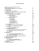
TABLE OF CONTENTS INTRODUCTION OF THE OWNERS MANUAL GENERAL PRECAUTIONS 1. PRECAUTIONS TO BE HEEDED FOR OPERATION 2. NAME OF PARTS 3. ACCESSORIES 4. ASSEMBLY AND INSTALLATION 5. PRECAUTIONS TO BE HEEDED WHEN MOVING MACHINE 6. CONTENTS OF GAME 7. EXPLANATION OF TEST AND DATA DISPLAY 7-1 SWITCH UNIT AND COIN METER 7-2 SYSTEM TEST MODE A C.R.T. TEST B COIN ASSIGNMENTS 7-3 GAME TEST MODE A INPUT TEST B OUTPUT TEST C SOUND TEST D VOLUME SETTING E GAME ASSIGNMENTS F BOOKKEEPING G BACKUP DATA CLEAR 8.
SPECIFICATIONS Installation space: 34 in.(W) x 71 in.(D) Height: 76 in. Weight: Approx. 450 lbs. Power maximum current: 5 Amp AC 120V 60 Hz MONITOR: 29” COLOR MONITOR INTRODUCTION OF THE OWNERS MANUAL SEGA ENTERPRISES, LTD., has for more than 30 years been supplying various innovative and popular amusement products to the world market.
General Precautions Follow Instructions: All operating and use instructions should be followed. Attachments: Do not use attachments not recommended by the product manufacturer as they may cause hazards. Accessories: Do not place this product on an unstable cart, stand, tripod, bracket, or table. The product may fall, causing serious injury to a child or adult, and serious damage to the product. Use only with a cart, stand, tripod, bracket, or table recommended by the manufacturer, or sold with the product.
Safety Check: Upon completion of any service or repairs to this product, ask the service technician to perform safety checks to determine that the product is in proper operating condition. Heat: The product should be situated away from heat sources such as radiators, heat registers, stoves, or other products (including amplifiers) that produce heat. Lithium Battery- Dispose of batteries only in accordance with the battery manufacturer’s recommendations.
1 . PRECAUTIONS TO BE HEEDED FOR OPERATION In order to prevent accidents, be sure to comply with the following points before and during operation. PRECAUTIONS TO BE HEEDED FOR OPERATION BEFORE STARTING THE OPERATION In order to avoid accidents, check the following before starting the operation: Check if all of the adjusters are in contact with the surface. If they are not, the cabinet can move and cause an accident. Do not climb on the product. Climbing on the product can cause falling accidents.
PRECAUTIONS TO BE HEEDED DURING OPERATION To avoid injury and accidents, those who fall under the following catagories are not allowed to play the game: * Intoxicated persons * Those who have high blood pressure or heart problems. * Those who have experienced muscle convulsion or loss of consciousness when playing video games, etc. * Persons susceptible to motion sickness. * Persons whose acts runs counter to the products warning displays.
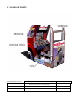
2 . NAME OF PARTS GAME SPECIFICATIONS WIDTH in. LENGTH in. HEIGHT in. WEIGHT lbs. All measurements are and rounded UP DURING SHIPPING 40” X 77” X 84” 500 LBS. WHEN ASSEMBLED 34” X 71” X 76” 450 LBS.
3 .
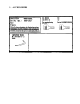
THE SHIPMENT METHOD DESCRIBED BELOW ONLY APPLIES TO ‘MODEL 3’ BOARDS CONTAINED IN THE FOLLOWING GAMES: LOST WORLD, VIRTUA FIGHTER 3, SUPER GT, SEGA BASS FISHING, STRIKER 2 HARLEY DAVIDSON, RALLY 2, DAYTONA 2, DIRT DEVILS, HOUSE OF THE DEAD 2, OCEAN HUNTER, STAR WARS TRILOGY, ZOMBIE REVENGE, CRAZY TAXI, ARILINE PILOTS, 18 WHEELER !!NEVER SHIP MODEL 3 / NAOMI GAME BOARDS OUTSIDE OF CAGE!! CARTON BOX 601-8928 (1) Used for transporting the GAME BOARD.
4 . ASSEMBLING AND INSTALLATION •Assembling should be performed as per this manual. Since this is a complex machine, erroneous assembling may cause damage to the machine, or malfunctioning to occur. •When assembling, be sure to perform work by plural persons. Depending on the assembly work, there are some cases in which a single person performing the work can cause personal injury or parts damage. •Be careful so as not to damage wirings. Damaged wiring can cause electric shock and short circuit hazards.
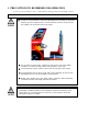
2 SECURING IN PLACE (ADJUSTER ADJUSTMENT) Be sure to have all the Adjusters make contact with the floor surface. Unless the Adjusters come into contact with the floor surface, the Cabinet can move of itself, causing an accident. This machine has 4 each of casters and adjusters (shown below). When the installation position is determined, cause the adjusters to come into contact with the floor directly, make adjustments in a manner so that the casters will be raised approximately 5mm.
3 POWER SUPPLY Ensure that the power cord is not exposed on the surface (passage, etc.). If exposed, they can be caught and are susceptible to damage. If damaged, the cord can cause an electric shock or short circuit. Ensure that the wiring position is not in the customer's passage way or the wiring has protective covering. Connect the game to the power supply and turn on power to the game.
ASSEMBLING CHECK 4 In the TEST MODE, ascertain that the assembly has been made correctly and that the IC BOARD is satisfactory. In the test mode, perform the following test: (1) MEMORY TEST MEMORY TEST MODE RAM TEST IC29 IC34 IC16 IC20 IC9 IC11 GOOD GOOD GOOD GOOD GOOD GOOD IC18 IC22 IC10 IC12 Selecting the RAM TEST item on the test mode menu screen causes the on-board memory to be tested automatically. The game board is satisfactory if the display beside each IC No. shows GOOD.
(3) INPUT TEST INPUT TEST COIN CHUTE #1 COIN CHUTE #2 SERVICE TEST START VIEW HORN SHIFT [L] SHIFT [H] SHIFT [R] HANDLE ACCEL BRAKE OFF OFF OFF OFF OFF OFF OFF OFF OFF OFF XXH XXH XXH Selecting the INPUT TEST on the test mode menu screen carses the screen (on which each switch is tested) to be displayed. Press each switch. For the coin switch test, insert a coin into the coin inlet with the coin chute door open.
5 . PRECATIONS TO BE HEEDED WHEN MOVING THE MACHINE When moving the machine, be sure to pull out the plug from the power supply. Moving the machine with the plug inserted can damage the power cord and cause a fire or electric shock. When moving the machine on the floor, retract the Adjusters and ensure that Casters make contact with the floor. During transportation, pay careful attention so that Casters do not tread power cords. Damaging the power cords can cause an electric shock and/or short circuit.
6 . CONTENTS OF GAME The following explanations apply in the event the product is functioning satisfactorily. Should there be any moves different from the following contents, some sort of faults may have occured. Immediately look into the cause of the fault and eliminate the cause thereof to ensure satisfactory operation. When the product is energized, the Billboard’s fluorescent lamp is always lit.
OPERATION SELECTOR : Turn right or left to select an object. GAME PLAY : Operate the Trailer Truck. SELECTOR : Decide GAME PLAY : Blow the horn to signal the car ahead to move out of the way or to have it increase the speed. Have the trailer ahead increase the speed. SELECTOR : Decide GAME PLAY : Increase your Trailer Truck speed, or stop it. SELECTOR : Void GAME PLAY : Decrease your Trailer Truck speed, or stop it.
SELECTOR TRUCK SELECT Select the truck from among ASPHALT COWBOY, STREAMLINE, HIGHWAY CAT, LONG HORN, and NIHONMARU. Each truck’s abilities in SPEED, TORQUE, and TOUGHNESS differ. TRAILER SELECT When starting in stage 2, 3, or 4, select the trailer for towing from the 2 trailers. The weight, the length, and the transportation fee differ. The heavier the trailer, the more the difficulty.
NAME ENTRY If your score falls within the top 5, you can enter your name.
Name of the destination point.
7 . EXPLANATION OF TEST AND DATA DISPLAY By operating the switch unit, periodically perform the tests and data check. When installing the machine initially or collecting cash, or when the machine does not function correctly, perform checks in accordance with the explanations given in this section. The following shows tests and modes that should be utilized as applicable. A NAOMI GAME BOARD is used for this product.
7 - 1 SWITCH UNIT AND COIN METER Never touch places other than those specified. Touching places not specified can cause electric shock and short circuit. Adjust to the optimum sound volume by considering the environmental requirements of the installation location. If the COIN METER and the game board are electrically disconnected, game play is not possible. Open the COIN CHUTE DOOR, and the switch unit shown will appear.
7 - 2 SYSTEM TEST MODE •The contents of settings changed in the TEST mode are stored when the TEST mode is finished from EXIT in the MENU mode. If the power is turned off before the TEST mode is finished, the contents of the setting changes do not take effect. •Executing “BACKUP DATA CLEAR” in the SYSTEM TEST MODE does not clear the BOOKKEEPING data in the GAME TEST MODE. •Entering the TEST mode clears fractional numbers of coins less than one credit and BONUS ADDER data.
A C.R.T. TEST 1) RGB COLOR ADJUSTMENT SCREEN In this screen, monitor color can be checked. C.R.T. TEST 1/2 1 32 RED Each of red, green, and blue is the darkest at the leftmost end, and becomes brighter towards the right-hand end in 31 gradiations. Monitor brightness is satisfactory if the white color bar is black at the left end and if it is white at the right end. Press the TEST button to proceed to the next screen.
B COIN ASSIGNMENTS The “COIN ASSIGNMENTS” mode permits you to set the start number of credits, as well as the basic numbers of coins and credits. This mode expresses “how many coins correspond to how many credits.” SETTING CHANGE PROCEDURE Setting changes cannot be stored unless the TEST BUTTON is pressed while the arrow is on EXIT. 1 Press the SERVICE BUTTON to move the arrow to the desired item. 2 Change the desired item setting by using the TEST BUTTON.
(C) MANUAL SETTING The Credit’s incremental increase settings as against a coin insertion are shown in further details than in (B) above (refer to Table 2). Also, note that when this MANUAL SETTING is performed, (B) COIN CREDIT setting becomes ineffective.
Table 1: COIN/CREDIT SETTING (COIN CHUTE COMMON TYPE) SETTING SETTING #1 SETTING #2 SETTING #3 SETTING #4 SETTING #5 SETTING #6 SETTING #7 SETTING #8 SETTING #9 SETTING #10 SETTING #11 SETTING #12 SETTING #13 SETTING #14 SETTING #15 SETTING #16 SETTING #17 SETTING #18 SETTING #19 SETTING #20 SETTING #21 SETTING #22 SETTING #23 SETTING #24 SETTING #25 SETTING #26 SETTING #27 FUNCTION OF CHUTE#1 1 COIN 1 CREDIT 1 COIN 2 CREDITS 1 COIN 3 CREDITS 1 COIN 4 CREDITS 1 COIN 5 CREDITS 1 COIN 2 CREDITS 1 COIN 5 C
Table 2: MANUAL SETTING COIN TO CREDIT 1 COIN 2 COINS 3 COINS 4 COINS 5 COINS 6 COINS 7 COINS 8 COINS 9 COINS 1 CREDIT 1 CREDIT 1 CREDIT 1 CREDIT 1 CREDIT 1 CREDIT 1 CREDIT 1 CREDIT 1 CREDIT BONUS ADDER NO BONUS ADDER 2 COINS GIVE 1 EXTRA COIN 3 COINS GIVE 1 EXTRA COIN 4 COINS GIVE 1 EXTRA COIN 5 COINS GIVE 1 EXTRA COIN 6 COINS GIVE 1 EXTRA COIN 7 COINS GIVE 1 EXTRA COIN 8 COINS GIVE 1 EXTRA COIN 9 COINS GIVE 1 EXTRA COIN COIN CHUTE (#1/#2) MULTIPLIER 1 1 1 1 1 1 1 1 1 COIN COUNTS AS COIN COUNTS AS
(G) SEQUENCE SETTING Number of credits required for starting a game, etc. can be set. Each sequence can be set between 1 ~ 5 credit(s).
7 - 3 GAME TEST MODE MENU MODE SYSTEM MENU 18 -WHEELER TEST MENU RAM TEST JVS TEST SOUND TEST C.R.T. TEST SYSTEM ASSIGNMENTS COIN ASSIGNMENTS BOOKKEEPING BACKUP DATA CLEAR CLOCK SETTING INPUT TEST OUTPUT TEST SOUND TEST C.R.T.
A. INPUT TEST Select INPUT TEST to have the screen shown below appear and to observe the status of each switch on the Control Panel. In this mode, Periodically check the status of each switch.
C. SOUND TEST Selecting the SOUND TEST displays the following screen on the monitor. This test mode allows each sound used in the game to be checked. Press the SERVICE button to move the arrow and select an item. Every time the TEST button is pressed, a different sound is played. SOUND TEST B. G. M. EFFECT [ ICS [ -> EXIT ] ] 0/ XX 0/ XX 0/ XX B. G. M. : Sounds used in the game can be played. EFFECT : Sound effects used in the game can be played.
E. VOLUME SETTING Selecting the VOLUME SETTING displays the following screen on the monitor. The volume of the detection for the steering wheel operation can be manually set. The value will be stored upon exiting from the item. VOLUME SETTING HANDLE SETTING SET CENTER [LOCK] 00H ->EXIT SELECT WITH SERVICE BUTTON PRESS TEST BUTTON TO EXIT SETTING THE STEERING WHEEL VOLUME 1 Press the SERVICE button to bring the arrow to SET CENTER. 2 “SET CENTER [LOCK]” display changes to “SET CENTER [SET].
F. BOOKKEEPING Selecting BOOKKEEPING in the MENU mode displays the data of the present operating status on 2 pages. Press the TEST button to proceed to the next screen. Pressing the TEST button while the second page is showing returns the screen to the MENU mode. BOOKKEEPING 1/2 NUMBER OF GAMES NUMBER OF CONTINUE AVERAGE PLAY TIME 0 0 00M00S PRESS TEST BUTTON TO CONTINUE NUMBER OF GAMES : Total number of plays. NUMBER OF CONTINUE : Total number of continues.
G. BACKUP DATA CLEAR Selecting the BACKUP DATA CLEAR displays the following screen on the monitor. In the GAME TEST MODE, this allows the contents of BOOKKEEPING and Player Ranking data to be cleared. The COIN/CREDIT related data can be cleared in the BACKUP DATA CLEAR in the SYSTEM TEST MODE. BACKUP DATA CLEAR YES (CLEAR) -> NO (CANCEL) SELECT WITH SERVICE BUTTON PRESS TEST BUTTON TO EXIT When clearing, use the SERVICE BUTTON to bring the arrow to “YES (CLEAR)” and press the TEST BUTTON.
8. HANDLE MECHA Be sure to turn power off before performing work, and avoid touching undesignated places. Failure to do so can result in electric shock and short circuit accidents. Be careful so as not to damage wirings. Damaged wiring can cause electric shock and short circuit hazards. Do not insert hand(s) into the mechanism so as not to cause hand(s) and fingers to be caught. Doing so can result in serious injury.
1 Turn the power off. 2 Take out the 4 truss screws at the center of the steering wheel to remove the FRAME HORN BUTTON, CUSHION U and the CAP HORN BUTTON. A small part (called the PIN HORN BUTTON) is attached to the CAP HORN BUTTON. Be sure to keep it. 3 Pull out the ROD HORN BUTTON. 4 Remove the SPRING and the CUSHION L. 5 Take out the hexagon nut. 6 Remove the WASHER HANDLE SHAFT. 7 Pull the STEERING HANDLE out of the HANDLE SHAFT.
13 Remove the HANDLE MECHA. Use CAUTION when performing this task. 14 When setting down the HANDLE MECHA, be sure to have the gear and sensor portions face up. Failure to do so may damage the parts due to the weight of the mechanism.
8 - 2 VOLUME ADJUSTMENT/REPLACEMENT Never touch places other than those specified. Touching unspecified places can cause electric shock and/or short circuit. After the replacement or adjustment of the VR, be sure to set the variable value of the VR in the test mode’s Volume Setting. Volume adjustment/replacement should be performed after the HANDLE MECHA has been removed as per 8 - 1. ADJUSTMENT 1 In order to turn the HANDLE SHAFT, insert the STEERING HANDLE into the HANDLE SHAFT.
REPLACEMENT 1 Disconnect the wiring connector. 2 Take out the 2 screws which secure the VOLUME BRACKET to remove the BRACKET together with the Volume. 3 Take out the 2 screws, remove the Volume Gear, and replace the Volume. 4 With the HANDLE SHAFT at the centering position, bring the gear into mesh so that the position of the volume’s shaft is as shown in the Fig. 5 Fasten the screws securing the VOLUME BRACKET. 6 After the work is finished, perform Volume Setting in the TEST mode.
9. SHIFT LEVER In order to prevent electric shock and short circuit, be sure to turn off the power before performing work on the interior parts of the product. Be careful not to damage wiring. Damaged wiring can cause electric shock or short circuit. Do not touch places other than those specified. Touching unspecified places can cause an electric shock or short circuit.
9 - 2 SWITCH REPLACEMENT Each Microswitch is secured with 2 screws. Remove the 2 screws and replace he Microswitch. After replacing the Switch, check its status in the Test Mode.
10. ACCELERATOR & BRAKE Be sure to turn power off before performing work, and avoid touching undesignated places. Failure to do so can result in electric shock and short circuit accidents. Be careful so as not to damage wirings. Damaged wiring can cause electric shock and short circuit hazards.
10 - 2 ADJUSTING OR REPLACING THE VOLUME Check Volume values in the Test Mode. Since work is performed inside the energized cabinet, be very careful not to touch undesignated portions. Touching places not specified can cause electric shock or short circuit. ADJUSTMENT 1 Take out the 2 truss screws and remove the Front Cover from the Accel. & Brake unit. 2 Loosen the screw which secures the Potentiobase, and adjust the Volume Value by moving the Base. 3 Secure the Potentiobase.
REPLACEMENT Be sure to turn the power off first, before performing work, and avoid touching unspecified places. Failure to do so can cause electric shock and/or short circuit. 1 Turn power off. 2 Take out the 2 truss screws and remove the Potentiocover. 3 Disconnect the connector of the volume to be replaced. 4 Remove the screw which secures the Potentiobase. 5 Remove the Potentiobase together with the volume attached. 6 Remove the base and the gear to replace the volume.
11 . COIN SELECTOR HANDLING THE COIN JAM If the coin is not rejected when the REJECT BUTTON is pressed, open the coin chute door and open the selector gate. After removing the jammed coin, put a normal coin in and check to see that the selector correctly functions. CLEANING THE COIN SELECTOR 1 2 3 4 5 6 GATE The coin selector should be cleaned once every 3 months. When cleaning, follow the procedure below: Turn the power for the machine OFF. Open the coin chute door.
OPTIONAL DOLLAR BILL ACCEPTOR THE COIN DOOR ASSEMBLY USED ON 18 WHEELER STD TYPE COMES EQUIPPED TO ACCEPT A DOLLAR BILL ACCEPTOR. ALL NEEDED WIRING CONNECTIONS ARE CONVIENENTLY LOCATED INSIDE THE GAME FOR THIS APPLICATION. THE COIN DOOR CAN ACCCOMMODATE THE FOLLOWING VALIDATOR(S): FORWARD-MOST HOLE POSITION **42-1155-00 Mars 2000 series MARS VALIDATOR $1, 2, 5 300 CAP The frame and cashbox enclosure on this coindoor has been modified to accomodate a Mars 2000 series upstacker.
**Coin door shown with optional dollar bill validator insered**
12. MONITOR 12 - 1 CAUTIONS AND WARNINGS CONCERNING THE SAFETY FOR HANDLING THE MONITORS When performing such work as installing and removing the monitor, inserting and disconnecting the external connectors to and from monitor, be sure to disconnect the power connector (plug) before starting work. Proceeding the work without following this instruction can cause electric shock of malfunctioning. Using the monitor by converting it without obtaining a prior permission is not allowed.
For the purpose of static prevention, special coating is applied to the CRT face of this product. To protect the coating, pay attention to the following points. Damaging the coating film can cause electric shock to the customers. For the caution to be heeded when clearing, refer to the Section of Periodic inspection Table. Do not apply or rub with a hard item (a rod with pointed edge, pen, etc.) to or on C.R.T. surfaces. Avoid applying stickers, seals, etc. on the C.R.T. face.
12 - 3 ADJUSTMENT METHOD Monitor adjustments are made at the time of shipment. Therefore, do not make further adjustments without a justifiable reason. Adjusting a monitor which contains high tension parts is dangerous work. Also, an erroneous adjustment can cause deviated synchronization and image fault, resulting in malfunction. When making adjustments, utilize a resinous Alignment Rod. Servicing with bare hands or using tools made of conductive material can cause electric shock.
13. REPLACING THE FLUORESCENT LAMP AND BUTTONS When performing the work, be sure to turn power off. Working with power on can cause an electric shock or short circuit accident. The Fluorescent Lamp, when it gets hot, can cause burns. Be very careful when replacing the Fluorescent Lamp. To perform work safely and securely, be sure to use a step which is in a secure and stable condition. Not using a step or using an unstable step can cause violent falling accidents.
4 The lamp is on the PCB side. Turn the metallic parts of the 2 buttons, unlock and remove the PCB from the buttons. 5 With the lamp pressed down, turn it counterclockwise to remove.
14. PERIODIC INSPECTION TABLE The items listed below require periodic checks and maintenance in order to retain the performance of this machine and ensure safe operation. Be sure to check once a year to see if Power Cords are damaged, the Plug is securley inserted, dust is accumulated between the Socket Outlet and the Power Plug, etc. Using the product when dust has accumulated can cause a fire or electrical shock.
15. TROUBLESHOOTING Should trouble occur, first check connector connections. PROBLEMS CAUSE With Main SW ON, no activation Power is not supplied. Plug in correctly Power supply/voltage is not correct. Make sure that power supply/voltage is correct. Check fuse. Remove the cause of overload and replace fuse AC main fuse causes the power to be cut off due to momentary overload. Operation is unsatisfactory Volume Setting Failure COUNTERMEASURES Perform Volume setting Adjust or replace V.R.
16. GAME BOARD In order to prevent an electrical shock, be sure to turn power off before performing work. Be careful so as not to damage wirings. Damaged wiring can cause an electric shock or short circuit accident. In this product, setting changes are made during the test mode. The Game BD need not be operated. Use the Game BD, etc. with the same settings made at the time of shipment. Do not expose the Game BD, etc. without good reason . 16 -1 LOCATING THE GAME BOARD 1 Turn power off.
16 - 2 COMPOSITION OF GAME BOARD Be sure to use the specified settings for the DIP SWes on the Filter Board. Failure to do so may cause irregularities or malfunctioning, such as unsatisfactory images displayed on the screen. ASSY CASE NAO PTR USA (840-00023D-01) DIP SW SETTING In this product, be sure to set all of the DIP SWes to OFF.
17. DESIGN RELATED PARTS 1 (4) 3 2 7 (6) 5 ITEM NO. 1 2 3 4 5 6 7 PART NO. 999-0916 999-0915 999-0910 999-0911 999-0912 999-0913 999-0914 DESCRIPTION MARQUEE PLEXI (MACHINED) OVERLAY - CONTROL PANEL DECAL - MAIN CAB L DECAL - MAIN CAB R DECAL - SEAT OUTSIDE L (INCL. EXHAUST) DECAL - SEAT OUTSIDE R (INCL.
18.
ASSY BILLBOARD (999-0922) ITEM NO. 1 2 3 4 5 6 7 PART NO.
ASSY STEERING UNIT
MODIFICATIONS TO PARTS ASSY #PTR-1000 (ASSY CHANGED TO PTR1-1000) PART NOT LISTED OR SHOWN IN DRAWING #999-0903 (3) Steering Spoke Cover Upper PART NOT LISTED OR SHOWN IN DRAWING #999-0904 (3) Steering Spoke Cover Lower Attached to Item #32 (Part No. PTR-2501 STEERING HANDLE) These parts are used for extra support/safety and are included in all US manufactured games.
ASSY AC UNIT (DRT1-0400) ITEM NO. 1 101 102 103 105 PART NO. SPG5-0401 600-5843-25 280-5143-6N34 Local Purchase 509-5453-91-V-B DESCRIPTION AC BRKT CA & PLUG ASSY 15A W/F-L=2.
ASSY COIN CHUTE TOWER (999-0923)
ASSY COIN CHUTE TOWER ITEM NO. (999-0923) PART NO. DESCRIPTION 1 2 3 4 5 6 7 8 9 10 11 INY-1180 PTR-1201 APC-0301 APC-0302 DRT-0301X DP-1167 105-5171 253-5366 421-7501-02 440-WS0002XEG 421-6591-01 SW UNIT TOWER COVER L COINCHUTE TOWER METER HOLE LID COIN METER BRKT TNG LKG CHUTE PLATE SINGLE CASH BOX STICKER 6.3V 0.15A STICKER W POWER OFF ENG STICKER COIN METER 101 102 103 107 108 109 40-6000-10EX 220-5643-01 220-5574 310-5029-F20 601-6231-C045 220-5575 ASSY C.
ASSY SWITCH UNIT (INY-1180) ITEM NO. PART NO.
ASSY HI/LOW/BACK SHIFTER (50-2771-00EX)
ASSY HI/LOW/BACK SHIFTER ITEM NO. 1 2 3 4 5 6 7 8 9 10 11 12 13 14 15 16 17 18 19 20 21 22 23 24 25 26 PART NO.
ASSY ACCEL AND BRAKE (SPG-2200)
ASSY ACCEL AND BRAKE (SPG-2200) ITEM NO. PART NO.
ASSY OF HANDLE MECHA
ASSY SENSOR UNIT (PTR-2550) ITEM NO. PART NO.
ASSY VR BUTTON START AND 1 VIEW (PTR-2600) ITEM NO. 1 2 3 101 102 103 PART NO.
ASSY WOOFER (999-0929) ITEM NO. 101 PART NO.
ASSY MAIN BOARD (PTR-4000) ITEM NO. PART NO. DESCRIPTION 1 2 3 PTR-4001 840-0023D-01 837-13844 MAIN BD BASE ASSY CASE NAO PTR EXP I/O CONTROL BD 2 FOR JVS FRI 201 202 203 204 000-P00416-W 011-T00316 011-T03512 011-F00312 M SCR PH W/FS M4 X 16 TAP SCR TH 3 X 16 TAP SCR TH 3.
ASSY AMP BOARD (PTR1-4200) ITEM NO. PART NO. DESCRIPTION PTR-4201 DRT-4502 421-7914-250630 AMP BD BASE FAN MOTOR BRKT STICKER AC 250V 6.3A 101 102 103 104 105 106 107 110 112 601-10369 560-5419-V 838-13723 260-0011-02 601-8543 514-5086-6300 514-5084 400-5397-01 310-5029-D20 STEREO PWR AMP 47 XFMR 100V 23V 9.6A X 2 WOOFER AMP 50W X 2 AXIAL FLOW FAN AC100V 50-60HZ FAN GUARD FUSE S.B 6.
ASSY OF POWER SUPPLY (PTR-4300) ITEM NO. PART NO. DESCRIPTION 1 2 3 PTR-4301 PTR-4302 PTR-4303 PWR SPLY BASE CONN BRKT VL3P CONN BRKT UP18P 101 106 838-11856-UL 560-5384 202 203 204 205 011-P00325 011-F00310 011-T03512 000-P00616-W CONNECT BD UL XFMR 100-200V 100V 10A WB AC 110 ~ 120V AREA TAP SCR PH 3 X 25 TAP SCR FH 3 X 10 TAP SCR TH 3.
VISIT OUR WEBSITE!