2ND PRINTING MARCH. 01 Standard Version Owner’s Manual SEGA ENTERPRISES, INC. USA MANUAL NO.
Warranty Your new Sega Product is covered for a period of 90 days from the date of shipment. This certifies that the Printed Circuit Boards, Power Supplies and Monitor are to be free of defects in workmanship or materials under normal operating conditions. This also certifies that all Interactive Control Assemblies are to be free from defects in workmanship and materials under normal operating conditions. No other product in this machine is hereby covered.
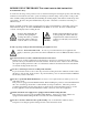
BEFORE USING THE PRODUCT, BE SURE TO READ THE FOLLOWING: To maintain the safety: To ensure the safe usage of the product, be sure to read the following before using the product. The following instructions are intended for the users, operators and the personnel in charge of the operation of the product. After carefully reading and sufficiently understanding the warning displays and cautions, handle the product appropriately.
Specification changes (removal of equipment, conversion and addition) not designated by SEGA are not allowed. The parts of the product include warning labels for safety, covers for personal protection, etc. It is very hazardous to operate the product by removing parts and or modifying the circuits. Should doors, lids and protective parts be damaged or lost, refrain from operating the product, and contact where the product was purchased from or the office herein stated.
TABLE OF CONTENTS BEFORE USING THE PRODUCT, BE SURE TO READ THE FOLLOWING: TABLE OF CONTENTS INTRODUCTION OF THE OWNER’S MANUAL 1. HANDLING PRECAUTIONS .......................................................................................... 2. PRECAUTIONS CONCERNING INSTALLATION LOCATION ................................... 3. OPERATION ..................................................................................................................... 4. ACCESSORIES ......................................
SPECIFICATIONS Installation Space Height Weight Power, maximum current For TAIWAN Power, current MONITOR : 1,360 mm (W) X 2,610 mm (D) (53.5 in. X 102.8 in.) : 2,230 mm (87.8 in.) : 450 kg. (992.1 lbs.) : 625 W 6.70 A (AC 120V 60 Hz AREA) 675 W 4.00 A (AC 220V 50 Hz AREA) 640 W 3.80 A (AC 220V 60 Hz AREA0 675 W 3.60 A (AC 240V 50 Hz AREA) : 750 W 9.20 A (MAX.) 350 W 3.80 A (MIN.
DEFINITION OF LOCATION MAINTENANCE MAN AND SERVICEMAN Non-technical personnel who do not have technical knowledge and expertise should refrain from performing such work that this manual requires the location's maintenance man or a serviceman to carry out, or work which is not explained in this manual. Failing to comply with this instruction can cause a severe accident such as electric shock.
1. HANDLING PRECAUTIONS When installing or inspecting the machine, be very careful of the following points and pay attention to ensure that the player can enjoy the game safely. Non-compliance with the following points or inappropriate handling running counter to the cautionary matters herein stated can cause personal injury or damage to the machine. Before performing work, be sure to turn power off. Performing the work without turning power off can cause an electric shock or short circuit.
2. PRECAUTIONS CONCERNING INSTALLATION LOCATION This product is an indoor game machine. Do not install it outside. Even indoors, avoid installing in places mentioned below so as not to cause a fire, electric shock, injury and or malfunctioning. Places subject to rain or water leakage, or places subject to high humidity in the proximity of an indoor swimming pool and or shower, etc. Places subject to direct sunlight, or places subject to high temperatures in the proximity of heating units, etc.
OPERATION AREA For the operation of this machine, secure a minimum area of 2.0m (W) X 2.8m (D). In order to prevent injury resulting from the falling down accident during game play, be sure to secure the minimum area for operation. Be sure to provide sufficient space so as to allow this product's ventilation fan to function efficiently. To avoid machine malfunctioning and a fire, do not place any obstacles near the ventilation opening.
3. OPERATION PRECAUTIONS TO BE HEEDED BEFORE STARTING THE OPERATION To avoid injury and trouble, be sure to constantly give careful attention to the behavior and manner of the visitors and players. In order to avoid accidents, check the following before starting the operation: To ensure maximum safety for the players and the customers, ensure that where the product is operated has sufficient lighting to allow any warnings to be read.
Do not put any heavy item on this product. Placing any heavy item on the product can cause a falling down accident or parts damage. Do not climb on the product. Climbing on the product can cause falling down accidents. To check the top portion of the product, use a step. To avoid electric shock, check to see if door & cover parts are damaged or omitted. To avoid electric shock, short circuit and or parts damage, do not put the following items on or in the periphery of the product.
Caution lookers-on so as not to touch the operating unit while in play. Failure to observe this may cause bodily contact with the player and trouble between the customers. Caution the player so as not to hold a child in her/his lap to play. Failure to observe this may cause the child to be caught between the Control Panel and the player and fall down. Be careful not to let anyone insert a part of his/her body into the void at the rear of the seat.
4. ACCESSORIES When transporting the machine, make sure that the following parts are supplied. TABLE 4 ACCESSORIES DESCRIPTION Part No. (Qty.) Note KEY MASTER 220-5576 (2) For opening/closing the doors OWNERS MANUAL 420-6588-01 (1) Figures KEY (2) For the CASHBOX DOOR If Part No. has no description, the Number has not been registered or can not be registered. Such a part may not be obtainable even if the customer desires to purchase it. Therefore, ensure that the part is in safekeeping with you.
FLEX TUBE 310-5050-220200 (1) For communication play, refer to Section 17. ASSY FIBER CABLE 600-6275-0500 (1) For communication play, refer to Section 17. NUMBER STICKER(for rear) 421-11304 (1) For communication play, refer to Section 17. CONN 22 310-5051-22 (2) For communication play, refer to Section 17. CARTON BOX 601-10642 (1) Used for transporting the Game Board. Refer to Next Page. NUMBER STICKER(for side) 421-11305 (1) For communication play, refer to Section 17.
HOW TO USE THE CARTON BOX STOP IMPORTANT When asking for the replacement or repair of the product's Game Board (SEGA HIKARU), be sure to put the Game Board together with the Shield Case in a Carton Box. Otherwise, the request is not acceptable. Put the Shield Case in the Carton Box by paying attention to the correct direction as per the following instructions and as shown by the instructions printed on the Carton Box. Handling in an erroneous manner can damage the Game Board.
5. ASSEMBLING AND INSTALLATION Perform assembly work by following the procedure herein stated. Failing to comply with the instructions can cause electric shock hazard. Perform assembling as per this manual. Since this is a complex machine, erroneous assembling can cause an electric shock, machine damage and or not functioning as per specified performance. When assembling, be sure to use plural persons.
When carrying out the assembling and installation, follow the following 6-item sequence. 1 SECURING IN PLACE (ADJUSTER ADJUSTMENT) 2 POWER SUPPLY CONNECTION 3 TURNING POWER ON 4 ASSEMBLING CHECK The master key (accessories) in addition to the tools such as a Phillips type screwdriver, wrench, socket wrench and Ratchet Handle are required for the assembly work.
1 SECURING IN PLACE (ADJUSTER ADJUSTMENT) Make sure that all of the adjusters are in contact with the floor. If they are not, the cabinet can move and cause an accident. This product has 6 casters and 6 Adjusters. (FIG. 5. 3a) When the installation position is determined, cause the adjusters to come into contact with the floor directly, make adjustments in a manner so that the casters will be raised approximately 5mm. from the floor and make sure that the machine position is level.
2 POWER SUPPLY, AND EARTH CONNECTION Be sure to independently use the power supply socket outlet equipped with an Earth Leakage Breaker. Using a power supply without an Earth Leakage Breaker can cause a fire when electric leakage occurs. Ensure that the "accurately grounded indoor earth terminal" and the earth wire cable are available (except in the case where a power cord plug with earth is used). This product is equipped with the earth terminal.
2 Connect one end of the earth wire to the AC Unit earth terminal, and the other end to the indoor earth terminal. The AC Unit earth terminal has a Bolt and Nut combination. Take off the Nut, pass the end of earth wire through the Bolt, and fasten the Nut. Note that the Earth Wire is incorporated in the Power Cord for the Areas of AC 120V (USA) and AC 220 ~ 240V, and therefore, this procedure is not necessary. Connect the Earth Wire to the Earth Terminal. FIG. 5.
3 TURNING POWER ON Connect the power by turning on the AC unit's main switch. Then the billboard's fluorescent light comes on. The monitor displays a system power-on message, and then an advertising screen (a plying-forhire screen) appears. At the same time the right and left speakers on the control panel output an advertise sound. The sound is inaudible, however, when you have disabled its function. Before an advertising screen appears the system automatically conducts an initialization.
ASSEMBLING CHECK 4 In the TEST MODE, ascertain that the assembly has been made correctly and IC BD. is satisfactory (refer to Section 8). In the test mode, perform the following test: (1) MEMORY TEST RAM TEST Selecting the RAM TEST on the system test mode menu screen causes the on-board memory to be tested automatically. The game board is satisfactory if the display beside each IC No. shows GOOD.
(3) SOUND TEST In the system test mode, selecting SOUND TEST causes the screen (on which sound related BD and wiring connections are tested) to be displayed. Check if the sound is satisfactorily emitted from each speaker and the sound volume is appropriate.
(5) OUTPUT TEST Select OUTPUT TEST from the Menu screen in the Game Test Mode to cause the screen (on which output unit such as lamps and wiring connections are tested) to appear. Ensure that the output unit functions satisfactorily. OUTPUT TEST > START BUTTON VIEW CHANGE BUTTON BASS SHAKER(FRONT) BASS SHAKER(FRONT+REAR) PRESS TEST BUTTON TO EXIT Perform the above inspections also at the time of monthly inspection.
6. PRECAUTIONS TO BE HEEDED WHEN MOVING THE MACHINE When moving the machine, be sure to unplug the power plug. Moving the machine with the plug as is inserted can damage the power cord and cause fire and electric shock hazards. When moving the machine on the floor, retract the Adjusters and ensure that Casters make contact with the floor. During transportation, pay careful attention so that Casters do not tread power cords and earth wires.
7. CONTENTS OF GAME The following explanations apply to the case the product is functioning satisfactorily. Should there be any moves different from the following contents, some sort of faults may have occurred. Immediately look into the cause of the fault and eliminate the cause thereof to ensure satisfactory operation. Advertising (Plying-for-Hire) Performance The billboard's fluorescent light is always on when the power is connected. The monitor displays the demonstration images and ranking data.
HOW TO PLAY Operation of a single machine allows a Single Play. Operation of interconnected machines allows a Communication Play. VIEW CHANGE BUTTON STEERING WHEEL HANDLE START BUTTON 4 SPEED SHIFTER SHIFT LEVER BRAKE PEDAL GAS (ACCELLETOR) PEDAL [Single Play] SEAT LOCK LEVER FIG. 7 b 1 Sit down on the seat. You can slide the seat back and forth. Facing the screen you can find the seat lock lever on the seat's right bottom. Pull it to unlock and slide the seat.
4 After you select a transmission, the TRANSMISSION SELECT screen race starts. If you press the view change button on the TRANSMISSION SELECT screen, you can activate a time attack mode. Rules with Time Attack Mode You drive a car alone to compete in the lap time. You must cycle the course within a limited time. If you succeed to cycle the course within a limited time, the remaining time is added to the limited time of a next cycling.
[Communication Play] Starting/playing procedures of a communication play are different from those of a single play. 1 When a player inserts the coins enough for one play, an entry screen appears. At the same time the start button flashes. 2 A player who wants a communication play must insert the coins (enough for one communication play) into the separate coin chute slot. A player who wants a single play must press the start button immediately when an entry screen appears.
8 Players compete with each other in the position. The top player can add the time remained after a cycling to the limited time of a next cycling. 9 When the top player clears the specified number of cycling times, the game is finished. If a player fails to cycle the course within a limited time, the game is over.
8. EXPLANATION OF TEST AND DATA DISPLAY By operating the switch unit, periodically perform the tests and data check. When installing the machine initially or collecting cash, or when the machine does not function correctly, perform checking in accordance with the explanations given in this section. The following shows tests and modes that should be utilized as applicable. SEGA HIKARU GAME BOARD is used for the product.
TABLE 8 EXPLANATION OF TEST MODE ITEMS DESCRIPTION INSTALLATION OF MACHINE When the machine is installed, perform the following: 1. Check to see that each setting is as per standard setting made at the time of shipment. 2. In the INPUT TEST mode, check such input devices as each SW, V.R., etc. 3. In the OUTPUT TEST mode, check such output devices as lamps, motors, etc. 4. In the SELF-TEST mode, check ICs on the IC Board.
8 - 1 SWITCH UNIT AND COIN METER Never touch places other than those specified. Touching places not specified can cause electric shock and short circuit hazards. Adjust to the optimum sound volume by considering the environmental requirements of the installation location. If the COIN METER and the game board are electrically disconnected, game play is not possible. A cover is provided on the bass shaker output adjustment volume in order to prevent the BASE SHAKER against being carelessly adjusted.
TEST BUTTON : For the handling of the test button, refer to the following pages. TEST SERVICE BUTTON : Gives credits without registering on the coin meter. SERVICE SOUND VOLUME : Adjusts the sound volume of the left and right speakers on the control panel. FRONT SPEAKER SOUND VOLUME : Adjusts the sound volume of the left and right speakers on the seat backrest.
8 - 2 SYSTEM TEST MODE A. SYSTEM TEST MODE MENU Press TEST Button to enter the TEST MODE, and the following Menu screen will be displayed. Press SERVICE Button to move the arrow (>) to the desired item and select with TEST Button. SYSTEM MENU XXXXXXXXX VERSION RAM TEST JVS TEST SOUND TEST C.R.T. TEST SYSTEM ASSIGNMENTS COIN ASSIGNMENTS BOOKKEEPING BACKUP DATA CLEAR ROMBD TEST CLOCK SETTING GAME TEST MODE > EXIT Bring the arrow to EXIT and press TEST Button to return to the GAME Mode.
C. JVS TEST In this test, Functioning of the I/O Board connected to Game Board is displayed and INPUT TEST can be performed. JVS TEST INPUT TEST > EXIT NODE 1/1 NAME SEGA ENTERPRISES,LTD.;837-13741 I/O CONTROL BD2;Ver0.15;99/06 CMD VER 1.1 JVS VER 2.0 COM VER 1.0 SWITCH 2PLAYERS 12BITS COIN 2SLOTS ANALOG 8CH DRIVER OUT 22CH SELECT WITH SERVICE BUTTON AND PRESS TEST BUTTON Execute EXIT to return to the MENU screen. When INPUT TEST is selected and executed, the following screen appears.
D. SOUND TEST This is a sound output test. Each speaker outputs the game's playing message in English.
E. C.R.T. TEST In this test, monitor adjustment can be performed. Periodically check to see if the monitor adjustment is appropriate in this test. This test consists of 2 screens. Use SERVICE Button to change the screen displayed. Press TEST Button to return to the MENU screen. C.R.T. TEST PAGE#1 0 31 RED GREEN The first screen displays color bars. The color adjustment can be checked. Each of red, green, blue is the darkest at the leftmost end, and becomes brighter towards the right-hand end.
F. SYSTEM ASSIGNMENTS STOP IMPORTANT Set the CABINET TYPE and MONITOR TYPE to a correct value according to the cabinet you use. If you fail to observe this, an error message appears when connecting the power and when exiting from a test mode; and eventually you cannot play the game. Performs setting for the whole system. Set each item in accordance with the cabinet. Use the items except ADVETISE SOUND and COMMUNICATION MODE as they are at the time of shipment.
G. COIN ASSIGNMENTS In this mode, the setting of incremental credit increase as against coin insertion can be changed. This test consists of 3 screens, and the following is the first screen. The setting done in the first screen will be stored when exited.
MANUAL SETTING When MANUAL SETTING is selected in the first screen, the following second screen appears. COIN ASSIGNMENTS MANUAL SETTING COIN TO CREDIT 1 BONUS ADDER 0 COIN CHUTE #1 MULTIPLIER 1 COINCOUNT AS 1COIN COIN 1 2 3 4 5 6 7 8 9 CREDIT 1 2 3 4 5 6 7 8 9 COIN CHUTE #2 MULTIPLIER 1 COINCOUNT AS 1COIN COIN 1 2 3 4 5 6 7 8 9 CREDIT 1 2 3 4 5 6 7 8 9 SEQUENCE SETTING > EXIT SELECT WITH SERVICE BUTTON AND PRESS TEST BUTTON COIN TO CREDIT determines how many coins are needed for one credit.
TABLE 1 COIN/CREDIT SETTING NAME OF SETTING SETTING SETTING SETTING SETTING SETTING SETTING SETTING SETTING SETTING SETTING SETTING SETTING SETTING SETTING SETTING #1 #2 #3 #4 #5 #6 #7 #8 #9 #10 #11 #12 #13 #14 #15 FUNCTIONING OF COIN CHUTE #1 1 1 1 1 1 1 1 1 1 1 1 2 1 1 1 2 1 COIN COIN COIN COIN COIN COIN COIN COIN COIN COIN COIN COINS COIN COIN COIN COINS COIN 1 2 3 4 5 2 5 3 4 5 6 1 1 2 1 3 3 CREDIT CREDITS CREDITS CREDITS CREDITS CREDITS CREDITS CREDITS CREDITS CREDITS CREDITS CREDIT CREDIT CREDI
Table 2: COIN/CREDIT SETTING (COIN CHUTE INDIVIDUAL TYPE) NAME OF SETTING SETTING #1 SETTING #2 SETTING #3 SETTING #4 SETTING #5 SETTING #11 SETTING #12 SETTING #15 SETTING #17 SETTING #18 SETTING #19 EACH SEAT'S COIN CHUTE 1 COIN 1 CREDIT 1 COIN 2 CREDITS 1 COIN 3 CREDITS 1 COIN 4 CREDITS 1 COIN 5 CREDITS 1 COIN 6 CREDITS 2 COINS 1 CREDIT 1 COIN 1 CREDIT 2 COINS 3 CREDITS 3 COINS 1 CREDIT 4 COINS 1 CREDIT 1 COIN 1 CREDIT 2 COINS 2 CREDITS 3 COINS 3 CREDITS 4 COINS 5 CREDITS NAME OF SETTING EACH SEAT'S C
SEQUENCE SETTING When SEQUENCE SETTING is selected in either first or second screen, the SEQUENCE SETTING Mode (the third screen) appears. In this mode, number of credits required for starting game can be set. COIN ASSIGNMENTS SEQUENCE SETTING SEQUENCE1 SEQUENCE2 SEQUENCE3 SEQUENCE4 SEQUENCE5 SEQUENCE6 SEQUENCE7 SEQUENCE8 > EXIT *CREDIT *CREDIT *CREDIT *CREDIT *CREDIT *CREDIT *CREDIT *CREDIT [ XXXXXXXXXXXXXXXXXXXXX ] [ SEGA ENTERPRISES,LTD.
H. BOOKKEEPING This allows such data as operating time/No. of coins inserted/ No. of credits to be checked, etc. This test consists of 2 screens. Pressing SERVICE Button causes screen to be changed. Press TEST Button to return to the MENU screen. On the first screen, such data as total time, coin, and credit are displayed.
I. BACKUP RAM CLEAR This enables you to clear the BOOKKEEPING data (coin- and credit-related data and TOTAL TIME data) in the SYSTEM MENU screen. NOTE: The same screen appears also in the GAME TEST MENU screen to clear the operating data. BACKUP DATA CLEAR YES (CLEAR) > NO (CANCEL) SELECT WITH SERVICE BUTTON AND PRESS TEST BUTTON Press the service button to move the > mark to YES (CLEAR) item, and press the test button. When the system completes clearing, a 'COMPLETED' message appears on the screen.
K. CLOCK SETTING The ranking data appears during advertising. It is automatically updated weekly; therefore correctly set the clock in the CLOCK SETING screen. YEAR, MONTH, DAY, HOUR, and MINUTE are set for SEGA HIKARU BD. Select the desired item with SERVICE Button and press TEST Button to increase the value. Bring the arrow to EXIT and press TEST Button to return to MENU Mode.
8 - 3 GAME TEST MODE A. GAME MENU Press the service button to move the > mark to GAME TEST MODE item, and press the test button. Then the following GAME TEST MODE screen appears. SYSTEM MENU XXXXXXX VERSION GAME TEST MENU RAM TEST JVS TEST SOUND TEST C.R.T.
B. INPUT TEST Press the service button to select the INPUT TEST item in the GAME TEST MENU screen, and press the test button. The following INPUT TEST screen appears. Periodically test the input devices by using the screen. INPUT TEST STEERING WHEEL GAS PEDAL BRAKE PEDAL GEAR POSITION START BUTTON VIEW CHANGE BUTTON SERVICE SWITCH TEST SWITCH XXX XXX XXX ON OFF OFF OFF OFF PRESS TEST AND SERVICE BUTTON TO EXIT • Each of STEERING WHEEL, GAS PEDAL, and BRAKE PEDAL indicates an analog value.
C. OUTPUT TEST Press the service button to select the OUTPUT TEST item in the GAME TEST MENU screen, and press the test button. The following OUTPUT TEST screen appears to test the output devices. Periodically test the output devices (the lights integrated with the START and VIEW CHANGE buttons and base shaker) by using the screen. OUTPUT TEST > START BUTTON VIEW CHANGE BUTTON BASS SHAKER(FRONT) BASS SHAKER(FRONT+REAR) PRESS TEST BUTTON TO EXIT Item is automatically changed or selected in turn.
D. FORCE FEEDBACK Press the service button to select the FORCE FEEDBACK item in the GAME TEST MENU screen, and press the test button. The following FORCE FEEDBACK screen appears to set the intensity of the force feedback against the steering wheel (handle) during playing. FORCE FEEDBACK (MIN 0 : MAX 10 : DEFAULT 9) FORCE = 9 UP DOWN FORCE TEST (FORCE = 4) CENTER OFF RIGHT OFF LEFT OFF > EXIT SELECT WITH SERVICE BUTTON AND PRESS TEST BUTTON FORCE : Indicates the intensity of the force feedback.
E. INPUT ASSIGNMENTS Press the service button to select the INPUT ASSIGNMENTS item in the GAME TEST MENU screen, and press the test button. The following INPUT ASSIGNMENTS screen appears to select the input device. INPUT ASSIGNMENTS STEERING (DEFAULT = 0) GAS PEDAL (DEFAULT = 0) BRAKE PEDAL (DEFAULT = 0) 0 0 0 DEFAULT SETTING > EXIT SELECT WITH SERVICE BUTTON AND PRESS TEST BUTTON Press the service button to move the > mark to a targeted input device to select, and press the test button.
Eb. GAS ASSIGNMENTS This screen enables to set the volume value of the gas pedal (accelerator). The MIN indicates the volume value when the pedal is not stepped on and the MAX when stepped on. Reset the volume value on this screen when the operability of the gas pedal is undesirable. Also newly set the volume value on this screen whenever you have adjusted or replaced the volume. GAS ASSIGNMENTS Check the '0' for a position on the screen.
F. GAME ASSIGNMENTS Press the service button to select the GAME ASSIGNMENTS item in the GAME TEST MENU screen, and press the test button. The following GAME ASSIGNMENTS screen appears to set the game mode, game difficulty, etc. Note that the GAME MODE and GAME DIFFICULTY items are displayed only when you have set the COMMUNICATION MODE to MASTER or NO LINK (See Chapter 9-2 F).
GAME DIFFICULTY : Sets the game's difficulty level. You can set it to VERY EASY, EASY, NORMAL, HARD, or VERY HARD. DEFAULT VIEW : Sets the viewpoint when a game is started. You can set it to DRIVER or REAR. SPEED DISPLAY : Sets the unit used to display the speed. You can set it to KM/H OR MPH. SEAT NUMBER : Sets the number of the cabinets interconnected for a communication play. Arrange them; and facing the screen set their SEAT NUMBER to 1, 2, 3, ...from left to right.
G. BOOKKEEPING Press the service button to select the BOOKKEEPING item in the GAME TEST MENU screen, and press the test button. The following BOOKKEEPING screens (1/2 & 2/2) appear to display the operation data. Press the service button to migrate between the 1/2 and 2/2 screens. After setting, select the EXIT and press the test button. The GAME TEST MENU screen reappears.
BOOKKEEPING 2/2 DRIVER SELECT Steve Park 0 Rusty Wallace 0 Dale Earnhardt 0 Bobby Hamilton 0 Terry Labonte 0 Mark Martin 0 Michael Waltrip 0 COURSE SELECT Talladega Richmond Watkins Glen 0 0 0 TRANSMISSION SELECT AUTOMATIC MANUAL 0 0 PRESS SERVICE BUTTON TO ANOTHER PAGE PRESS TEST BUTTON TO EXIT DRIVER SELECT : Displays the number of selection times for the most frequently selected 7 players. COURSE SELECT : Displays the number of selection times by course.
H. BACKUP DATA CLEAR Press the service button to select the BACKUP DATA CLEAR item in the GAME TEST MENU screen, and press the test button. This screen enables to clear the BOOKKEEPING data and the ranking data. BACKUP DATA CLEAR > YES (CLEAR) NO (CANCEL) SELECT WITH SERVICE BUTTON AND PRESS TEST BUTTON Press the service button to move the > mark to YES (CLEAR) item, and press the test button. When the system completes clearing, a 'COMPLETED' message appears on the screen.
9. CONTROL PANEL (STEERING MOTOR UNIT) Before starting to work, ensure that the Power SW is OFF. Failure to observe this can cause electric shock or short circuit. Use care so as not to damage wirings. Damaged wiring can cause electric shock or short circuit. Do not touch undesignated places. Touching places not designated can cause electric shock or short circuit. This work should be performed by the Location's Maintenance Man or Serviceman.
4 The V.R. is on the VR BASE (a white, plastic made part). Loosen the 2 screws which secure the VR BASE and adjust the angle and appropriateness of gear mesh by moving the VR BASE. 5 Adjust to an appropriate mesh by securing the Steering Wheel in the direction allowing the car to advance straight forward and ensuring the "D" CUT FACE of the Volume shaft is oriented as shown. 6 Tighten the 2 screws to secure the VR BASE. VR BASE SCREW (2) M4 X 12, w/flat & spring washers "D" CUT FACE FIG. 9.
REPLACING THE VOLUME SCREW (2) M4 X 12, w/flat & spring washers 1 Disconnect the connector from the Volume. 2 Take out 2 screws to remove the Volume together with VR BASE from the HANDLE MECHA. PHOTO 9. 1 b VR BASE 3 Take out 2 screws from the VR BASE reverse side to remove the Volume together with VR Bracket from the VR BASE. 4 Remove the Volume from VR Bracket and replace. TRUSS SCREW (2) M4 X 12 PHOTO 9.
5 After replacing the Volume, engage the gears at the angular position shown and fix the VR Bracket. VR BASE SCREW (2) M4 X 12, w/flat & spring washers FIG. 9. 1 b V.R. 220-5484 220-5373 6 Turn on power. 7 Set the Center Value of the Volume in the TEST mode. 8 In the TEST mode, check to see if the Volume Value varies smoothly in accordance with the steering wheel operation. 9 - 2 GREASING STOP IMPORTANT Be sure to use the designated grease. Using undesignated grease can cause parts damage.
10. 4-SPEED SHIFTER (SHIFT LEVER) Before starting to work, ensure that the Power SW is OFF. Failure to observe this can cause electric shock or short circuit. Use care so as not to damage wirings. Damaged wiring can cause electric shock or short circuit. Do not touch undesignated places. Touching places not designated can cause electric shock or short circuit. This work should be performed by the Location's Maintenance Man or Serviceman.
4 Pull up the 4-speed shifter upright. Be careful not to let the wires caught on some sections or not to let the parts hit against each other. 5 Disconnect the connectors from each other. Uncouple the 4-speed shifter. When replacing it to an original position, be careful about the installation direction. The side with the wires must face the PTV. When replacing it to an original position, be careful about the installation direction. Disconnect the connector. PHOTO 10.
10 - 2 REPLACING THE SWITCH In case 4-speed Shifter operability is poor, malfunction of or damage to the Microswitch of Mechanism can be considered. The 4-speed Shifter has 3 Microswitches. Be sure to check which Switch malfunctions prior to performing work. 1 Remove 4-speed Shifter as per procedure 10 -1. 2 Disconnect the wiring connected to the Microswitch. 3 Take out 2 screws to replace the Microswitch. 4 Check to ensure that the Switch goes ON and OFF in consistency with the operation.
11. ACCELERATOR & BRAKE Before starting to work, ensure that the Power SW is OFF. Failure to observe this can cause electric shock or short circuit. Use care so as not to damage wirings. Damaged wiring can cause electric shock or short circuit. Do not touch undesignated places. Touching places not designated can cause electric shock or short circuit. This work should be performed by the Location's Maintenance Man or Serviceman. Performing work by non-technical personnel can cause electric shock hazard.
REPLACING THE VOLUME TRUSS SCREW (2) M4 X 8 POTENTIOCOVER 1 Turn the power off. 2 Take out the 2 screws and remove the Potentiocover (FIG. 11. 1 c). 3 Disconnect the connector of the Volume to be replaced. 4 Remove the screw which secures the Potentiobase (FIG. 11. 1 b). 5 Remove the Potentiobase together with the Volume as is attached. (FIG. 11. 1 c) 6 Remove the Base and Gear to replace the Volume. 7 Adjust the Volume as per the previous page after replacing. FIG. 11.
12. COIN SELECTOR HANDLING THE COIN JAM If the coin is not rejected when the REJECT button is pressed, open the coin chute door and open the selector gate. After removing the jammed coin, put a normal coin in and check to see that the selector correctly functions. CLEANING THE COIN SELECTOR GATE Remove and clean smears by using a soft cloth dipped in water or diluted chemical detergent and then squeezed dry. Never apply machine oil, etc. to the Coin Selector.
WELLS-GARDNER WGD15-2110-01 OVER/UNDER MINI DOOR 2 ENTRIES WITH BILL VALIDATOR BOTTOM DOOR & SPECIAL ENCLOSURE ELECTRONICS CORPORATION 2701 N. KILDARE CHICAGO, IL 60639 1-800-336-6630 WWW.WGEC.COM # 12 20 16 15 18 17 25 28 19 21 22 6 5 8 27 7 4 13 5 23 63 3 14 1 2 29 9 10 4 8 26 F 11 J K B D L 24 E C A 5 G H M DESCRIPTION W.G.
Tom Happ Ph: 847-593-6161 ext. 107 tom.happ@happcontrols.com Fx: 847-956-2091 Happ Controls, 106 Garlisch Drive, Elk Grove, IL 60007 Visit our website http://www.happcontrols.
OPTIONAL DOLLAR BILL ACCEPTOR THE COIN DOOR ASSEMBLY USED ON NASCAR DX TYPE COMES EQUIPPED TO ACCEPT A DOLLAR BILL ACCEPTOR. ALL NEEDED WIRING CONNECTIONS ARE CONVIENENTLY LOCATED INSIDE THE GAME FOR THIS APPLICATION. THE COIN DOOR CAN ACCCOMMODATE THE FOLLOWING VALIDATOR(S): FORWARD-MOST HOLE POSITION **42-1155-00 Mars 2000 series MARS VALIDATOR $1, 2, 5 300 CAP The frame and cashbox enclosure on this coindoor has been modified to accomodate a Mars 2000 series upstacker.
**Coin door shown with optional dollar bill validator inserted** 66
13. REPLACING THE FLUORESCENT LAMP, AND LAMPS When performing work, be sure to turn power off. Working with power on can cause electric shock and short circuit hazards. The Fluorescent Lamp, when it gets hot, can cause burn. Be very careful when replacing the Fluorescent Lamp. Be sure to use lamps of the designated rating. Using lamps of undesignated rating can cause a fire or malfunctioning. To perform work safely and securely, be sure to prepare a step which is in a secure and stable condition.
SWITCH PLATE START BUTTON,VIEW CHANGE BUTTON 1 Turn power off. 2 Remove the 4 Trusshead screws. TRUSS SCREW (4) M4 X 8, chrome 3 Remove the switch plate from the control panel carefully without damaging the wires. PHOTO 13 a 4 On the rear side of the switch plate there is a metallic projection on the foot of each button. Turn the projection to unlock, and remove the wire connection part from the button body. Unlock. PHOTO 13 b 5 The lamp is inside the wiring connecting portion.
14. PERIODIC INSPECTION TABLE The items listed below require periodic check and maintenance to retain the performance of this machine and to ensure safe business operation. When handling the controller, the player will be in direct contact with it . In order to always allow the player to enjoy the game, be sure to clean it regularly. Also, it is advisable to provide wet tissue, etc. available for player use.
SEAT (Greasing to Seat Rail Portion) Move the Seat to the rearmost portion and apply spray greasing to the portion shown at the right once every 3 months by using NOK KLUBER L60 or GREASE MATE SEGA PART No. 090-0066. After greasing, move the Seat a few times forward and backward so as to allow the grease to be applied all over uniformly. Be sure to wipe grease which attaches to the surfaces of the PROTECT RUBBER on the Seat Rail, or any excess grease. 70 FIG.
15. TROUBLESHOOTING In order to prevent electric shock and short circuit, be sure to turn power off before performing work. Be careful so as not to damage wirings. Damaged wiring can cause electric shock or short circuit. After removing the cause of the functioning of the Circuit Protector, reinstate the Circuit Protector. Depending on the cause of the functioning, using the Circuit Protector as is without removing the cause can cause generation of heat and fire hazard.
TABLE 15 b PROBLEMS BASE SHAKER does not react. CAUSE COUNTERMEASURES Adjust the SWITCH UNIT's volume. (see 8-1) Incorrect volume adjustment. Failure of the AMP or BASE SHAKER Operability of the Steering wheel (handle) is poor. Perform the OUTPUT TEST. (see 8-3) Deviation of the volume value. Adjust the volume value in the Test mode. (see 8-3) Volume gear engagement fault. Adjust the engagement of the gear. (see 9-2) Volume malfunctioning. Replace the Volume.
16. GAME BOARD In order to prevent electric shock and short circuit hazards, be sure to turn power off before performing work. Be careful so as not to damage wirings. Damaged wiring can cause fire, electric shock and short circuit hazards. Do not expose the Game BD, etc. without a good reason. Failure to observe this can cause electric shock hazard or malfunctioning. The electronic parts on the IC Board could be damaged due to human body's static electricity.
16 - 1 REMOVING THE GAME BOARD 1 Turn power off. 2 Remove the 2 trusshead screws of the back lid, unlock it, and detach it from the main cabinet. 3 Disconnect the connectors of all the wires between the ASSY MAIN BD STD and the main cabinet. 4 Disconnect the connectors of all the wires between the shield case's filter board on the ASSY MAIN BD STD and the main cabinet. 5 Remove the 2 wing bolts that fix the base (a wooden plate) of the ASSY MAIN BD STD. WING BOLT (2) M4 X 25, flat washer used.
6 Draw out the ASSY MAIN BD STD from the main cabinet. More than two workers must engage in this action. Note that the ASSY MAIN BD STD is heavy, and, if a single worker draws out it alone, he/she may damage the wires by snagging or catching the wires on other parts. NOTE: If you remove the 3 screws and detach the shield case lid, you can access to the game board. This action is allowed, however, only for the Sega's service engineer. To perform work safely, use 2 or more workers.
16 - 2 COMPOSITION OF GAME BOARD GAME BD NCR (833-14033) SCREW (3) M3 X 50, w/flat & spring washers SCREW (2) M3 X 70, w/flat & spring washers SAMURAI COMMUNICATION BD 837-13404 FLANGE NUT (8) M3, plastic washer used. SAMURAI EXTEND SOUND BOARD 837-13629 ROM BD NCR 834-14125 MAIN BD SEGA HIKARU 834-13821-01 BD TRAY FOR SEGA HIKARU 105-5380 FIG. 16.
17. COMMUNICATION PLAY For this game, up to 8 machines can be connected to allow up to 8 players to play simultaneously. In this instance, connecting the communication cable and setting for the communication play are required. 17 - 1 INSTALLATION PRECAUTIONS Before starting to work, ensure that the Power SW is OFF. Failure to observe this can cause electric shock or short circuit. Use care so as not to damage wirings. Damaged wiring can cause electric shock or short circuit.
DISTANCE BETWEEN MACHINES Be sure to secure space in excess of 70cm between machines. 70cm 70cm FIG. 17. 1 17 - 2 CONNECTING THE COMMUNICATION CABLE To enable the game machines to serve in a communication play, you must interconnect their game boards with the communication cables (optical fiber cables). As for a wiring of the communication cables within the main cabinet (between the game board and the connector plate), Sega has completed it before shipping. Each connector plate has two connectors.
4 Remove the 2 screws to detach the hole lid from the connector box. Depending on the number and arrangement of the interconnected game machines, you may remove either or both of the 2 hole lids. (Fig. 17. 2a) Connect the Communication cable. SCREW (2) black M3 X 8, w/flat & spring washers HOLE LID TRUSS SCREW (4) black M4 X 16 CONNECTOR BOX FIG. 17.
5 Attach CONNECTOR 22 to the both ends of FLEX TUBE. First, disassemble CONNECTOR 22 (Fig. 17. 2 b). 6 First pass the plastic nut through the flex tube. Otherwise, the following work can not be performed and therefore, be very careful of this point. 7 Install the holder and then the "insert" to the end of the flex tube by turning them as in bolts and nuts (Fig. 17. 2 c). 8 Tighten the plastic nut to the connector.
8 Wire the communication cables. A wiring method (connecting which connector to which connector) varies depending on the number of the game machines to interconnect. Wire exactly according to the illustration below. For the number other than in the illustration, always connect the TX of one game machine to the RX of the other, and thereby make a loop of the communication cable finally. (Fig. 17. 2f) FIG. 17.
9 Fix the connector box onto the main cabinet. Use the 4 trusshead screws that you removed previously. 10 Arrange the game machines. See Chapter 6 for the precautions in transportation. Keep a space between the game machines as wide as possible. 11 Contact the adjusters of all the game machines to the floor. (Sec. 5 3 ) 12 Connect the power cords and the grounding cables. (Sec. 5 4 ) 13 Put the number stickers on the game machines. Facing the PTV screens, put the stickers '1' '2' '3' ...
17 - 3 SETTING FOR COMMUNICATION PLAY STOP IMPORTANT During communication play, if the test mode is not finished within 3 minutes on all the linked machines, the NETWORK CHECK cannot be performed, causing NETWORK ERROR. Change the game setting for each seat in a manner so as to meet communication play. If the setting is not correct, communication play cannot be played. SETTING FOR COMMUNICATION PLAY 1 Turn the linked machines' power on. 2 Cause all of the machines to enter the test mode.
GAME ASSIGNMENTS GAME MODE(SINGLE) NORMAL GAME MODE(NETWORK) NORMAL GAME DIFFICULTY NORMAL DEFALT VIEW DRIVER SPEED DISPLAY KM/H > SEAT NUMBER X EXIT SELECT WITH SERVICE BUTTON AND PRESS TEST BUTTON FIG. 17. 3 b Cause all of the machines to exit from the test mode. After the test mode, the screens proceed to and display the NETWORK CHECK. When a network-checking is finished, the system displays am advertisement screen. This means a successful completion of setting.
18. DESIGN RELATED PARTS 1 8 3 9 6 12 7 11 10 4 ITEM NO. 1 NOT SHOWN 3 4 NOT SHOWN 6 7 8 9 10 11 12 NOT SHOWN NOT SHOWN PART NO. DESCRIPTION 999-1062 999-1072 999-1073 999-1077 999-1076 999-1063 999-1078 999-1071 999-1079 999-1080 999-1075 999-1074 999-1081 999-1082 PANEL DISPLAY POP DECAL CABINET LEFT SIDE 6-COL. DECAL CABINET RIGHT SIDE 6-COL.
21. PARTS LIST 1 TOP ASSY NCR STD 1 2 4 5 3 7 6 ITEM NO. PART NO.
2 AC UNIT ITEM NO. PART NO.
3 FAN UNIT (STR-1070) CONNECTOR ITEM NO. PART NO.
4 ASSY CONNECTOR PLATE (NCR-1080) ITEM NO. PART NO.
5 SW UNIT (NCR-1150) 4 ITEM NO. PART NO.
6 ASSY CTRL PNL 1 4 2 3 ITEM NO. 1 2 3 4 NOT SHOWN NOT SHOWN PART NO. DESCRIPTION SPG-2001 SPG-2002 999-1070 999-1069 DYN-1209X SPG-2039 STEERING WHEEL STEERING EMBLEM PUSH BUTTON RECT.
7 ASSY HANDLE MECHA (NCR - 2100) 92 (D-1/2)
7 ASSY HANDLE MECHA (NCR - 2100) ITEM NO. 1 2 3 4 5 6 7 8 9 10 11 12 13 14 15 101 102 103 104 105 106 107 PART NO.
8 PEDAL UNIT (NCR-2200) SCREW FASTENING TORQUE TO BE M8 X 18 N•m ITEM NO. PART NO.
9 ASSY ACCEL&BRAKE (SPG-2200) (D-1/2) 95
9 ASSY ACCEL&BRAKE (SPG-2200) (D-2/2) ITEM NO. PART NO.
10 ASSY 4SPEED SHIFTER (NCR-2150) (D-1/2) 97
10 ASSY 4SPEED SHIFTER (NCR-2150) (D-2/2) ITEM NO. PART NO.
SCREW FASTENING TORQUE TO BE M8 Bolt for fastening plastic: 8.3N•m M8 Others: 19.9N•m M4 Sonic Lock Portion: 0.
11 ASSY SEAT (NCR-2400) ITEM NO. (D-2/2) PART NO.
NOTE: MAKE SURE THAT THERE IS NO WIRING, ETC. IN THE SLASH MARK PORTIONS.
12 ASSY MAIN BD STD (D-2/2) ITEM NO. PART NO.
13 ASSY SHIELD CASE NCR (NCR-4050) 103 (D-1/2)
13 ASSY SHIELD CASE NCR (NCR-4050) ITEM NO. PART NO.
105 IN THE SLASH MARK PORTIONS. 2. Set the 838-13578 (áB) jumper as illustrated. NOTE: 1. MAKE SURE THAT THERE IS NO WIRING, ETC.
14 ASSY AMP BD (NCR-4100) (D-2/2) ITEM NO. PART NO.
107 IN THE SLASH MARK PORTIONS. 2. Set all the DIP switches (837-13844 (áB) and 838-13366 (áC)) to OFF. NOTE: 1. MAKE SURE THAT THERE IS NO WIRING, ETC.
15 ASSY ELEC (NCR-4200) ITEM NO. (D-2/2) PART NO. DESCRIPTION NCR-4201 NCR-4202 837-13844 838-13366 838-12912-01 421-7468-01 WOODEN ELEC BASE C.P.BRKT I/O CONTROL BD 2 FOR JVS FRI DRIVE BD SRT SERVO MOTOR DRIVE BD NEW STICKER C.P W/PIC 102 103 998-0135 117-5225 104 105 106 108 512-5046-15000 310-5029-K20 280-5009-01 601-0460 POWER TRANSFORMER ER-501 FUSES 1-6.25 A SLOW BLOW 2-3A SLOW BLOW 1-15A SLOW BLOW C.
22. WIRE COLOR CODE TABLE THE WIRE COLOR CODE is as follow: A B C D E PINK SKY BLUE BROWN PURPLE LIGHT GREEN Wires other than those of any of the above 5 single colors will be displayed by 2 alphanumeric characters. 1 2 3 4 5 7 8 9 RED BLUE YELLOW GREEN WHITE ORANGE BLACK GRAY If the right-hand side numeral of the code is 0, then the wire will be of a single color shown by the left-hand side numeral (see the above).
VISIT OUR WEBSITE!