Sega G-80 Multigame Instruction Manual Version 1.0 Copyright © 1998, Clay Cowgill clayc@diamondmm.com Sega G-80 Multigame, Version 1.
Notice Regarding this Upgrade Warning! Although this upgrade has been tested and the techniques used will not directly cause harm to your Sega G-80 System, if you do something wrong, you can very seriously damage the game electronics! To perform this upgrade you should: • Be familiar with safe handling procedures for electronic components. • Be able to remove and replace socketed IC’s (chips) without causing damage. • Be able to follow directions.
The Sega G-80 Multigame (the “kit”) consists of two assembled printed circuit boards and a replacement PROM. When installed on the CPU board of Sega G-80 Vector Game (Star Trek, Zektor, Space Fury, Eliminator, or Tac/Scan) the kit eliminates the need for the EPROM board and allows all the Sega G-80 vector games to be played from a single cabinet. Games are selected from an on-screen menu system. These instructions describe how to install the kit into a working Sega G-80 arcade game.
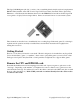
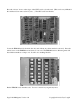
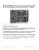
Press the “release” levers on the edges of the CPU board to eject the card. (This can be very difficult if the card hasn’t been removed in 15 years…) The CPU card looks like this: Locate the EPROM card (it should be the only card without any cables attached to the end). Press the release levers on the EPROM card and remove it as well. The EPROM card for different games will have different numbers of chips on it. It will look something like this: Put the EPROM card somewhere safe.
Upgrading the CPU card: We’ll be removing four chips from the CPU card. They are: • • • • U15 – a 16 pin PROM U21 – a 40 pin security chip U25 – a 24 pin 2K EPROM U22 – a 40 pin Z-80 processor (usually U22 is not labeled on the PCB) Using a small-blade standard screwdriver or chip puller, remove the four chips listed above and place them in a static-safe area. (Be sure you didn’t bend any pins—if you did, bend them back carefully.
Place the replacement PROM in socket U15 so that the notch is pointed towards the end of the CPU card that the red “test” switch is on. The notch should be facing the same direction as the 7400 at U14 and the 7408 at U13. Press it firmly into the socket. Make sure all the pins line up and go into the socket. Put it back together and test: The CPU card is now complete. Plug the CPU card back into the card cage.
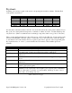
Try it out: Assuming you now have a game on the screen, coin-up and play around for a minute. The Star Trek control panel is used like so: Game Star Trek Eliminator Space Fury Tac/Scan Zektor Spinner rotate rotate rotate “Warp” warp rotate left rotate left - “Photon” photon rotate right rotate right - “Thrust” thrust thrust thrust add ship thrust “Fire” fire fire fire fire fire You may have noticed that “thrust” and “fire” are reversed from how the control panel is labeled.
Space Fury Self Test Space Fury, with no control changes. You can use this with a Space Fury control panel to play Space Fury. The self test runs much like a “standard” self test on the G-80. To skip tests, hold down both Player 1 and Player 2 start buttons for several seconds and then release them. ROM tests are not performed. Sound tests are limited to the Universal Sound Board and Star Trek Speech board. When complete, the test will run Star Trek.
Technical information: This info is for any of you technical-types that want to make your own speech-switchers, sound switchers, or whatever. You’ll notice that the Daughtercard has an expansion header on it. This gives you access to two 8-bit output latches.