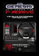
FM-DRIVE 2612 VST USER MANUAL 1.
Table of Contents FM-DRIVE 2612 VST ...................................................................................................................... 1 INTRODUCTION............................................................................................................................. 3 INSTALLATION............................................................................................................................... 6 CONTROL PANELS ..........................................................
INTRODUCTION My name is Aly James; French steam funky musician, composer and creator of strange musical DIY devices and software. Normally I am more inclined to make some guitar & bass oriented devices but I am also a fan of the SEGA GENESIS/MEGADRIVE sound, it was my first console and it opens up my imagination and lot. I was not very used to tracker music making or MML programming, which is why I needed an YM2612 Vst Instrument, for personal use. Also I needed a way to control the real hardware via MIDI.
Mainly, FMDRIVE can act either as the YM2612 CH1, 2, 3(with special mode or CSM) 4, 5 or 6 (FM or DAC). It can be either polyphonic (up to 6 voices) or mono like the real chip and can act as 6 YM2612 channels at once with the same patch when in poly mode... However you have to load 6 instances of the VST to have the YM2612 six channels original setup. This particular implementation allows getting over the original six channels limit if ones need it.
INSTALLATION COMPATIBILITY FMDRIVE is a Windows 32Bit VST Instrument for use with MIDI capable DAWs. RUN on 32/64 Bit Systems. If you want to use it with a 64bit DAW you can use JBridge. INSTALL VST 1. Decompress the downloaded archive file 2. Copy the entire Folder AJLAB to your VST PLUGINS folder 3. Load it in your DAW INSTALL STANDALONE 1. Decompress the downloaded archive file 2. Copy the entire Folder FMDRIVE where you want 3. Simply RUN FMDRIVE.
State of FMDRIVE 2612 current features WIN 32 VST runs on 32/64Bit Systems and it is multicore compatible HIGH QUALITY GUI (Different panels for controls etc...
YM2612 extended switchable features OVERDRIVE LADDER EFFECT CONTROL (Works only in MD1 MODE, adjust to taste) RATE RATIO CONTROL (Change the global EG RATE/SPEED from *0.1 to *4 for rapid tweaking/adjustment of the envelopes) GRAPHIC EG Up to 8 stages /8 stage shapes/custom loop point (aka custom SSG) and sustain point. CUSTOM LFO RATE (for low modulation...
LOAD & SAVE FULL PATCH & BANKS in FXB/FXP CONTROLS THE REAL MEGADRIVE HARDWARE VIA MIDI (Needed Little Scale GENMDM Midi Device) CONTROL PANELS FMDRIVE GUI INTERFACE stores the different parameters on different panels The central visual interface can be opened or closed clicking on the led next to power on.
Right click on a knob, button or slider will open a midi learn assign menu. Ctrl click + move allow fine tuning.
THE YAMAHA YM2612 FM CHIP The YM2612, aka OPN2, is a six-channel sound chip developed by Yamaha. It belongs to Yamaha's OPN family of FM synthesis chips used in several game and computer systems. It was most notably used in the Sega Mega Drive/Sega Genesis game console.
The particular implementation of the DAC produces some noticeable artifacts on the Sega Megadrive sound output, similar to distortion, the sound can clip at high levels and the sine wave output start to change at low volume, mixed with a squared signal. The chip was also stripped of its predecessor’s (YM2608) SSG component, although its vestigial SSG envelope generator is still functional. OPERATOR CORE Each Operator is switchable Mask on/off to receive note on/off commands.
DT1: Fine detune/ following this table (frequency is a small number) small detuning can create movement on the sound. DT1 FREQUENCY DETUNE 0 0 1 1 2 2 3 3 4 0 5 -1 6 -2 7 -3 DT2: Coarse detune/ Large frequency detune (modeled after YM2151 chip) DT2 F-DETUNE HZ 0 0 1 19.4 2 21.58 3 23.77 AM: Enable LFO Amplitude Modulation (AMS) for that Operator. Relevant only if both the LFO is enabled and AMS (amplitude modulation sensitivity) is non-zero.
ENVELOPE GENERATORS PARAMETRIC ENVELOPES The typo used for naming the envelope stages varies with documentations, FMDRIVE uses: AR, DR, SL, D2R and RR for Attack, First Decay, Sustain Level, Secondary Decay and Release. The sound starts when the key is depressed, a process called ‘key on’. The sound has an attack, a strong primary decay, followed by a slow secondary decay. The sound continues this secondary decay until the key is released, a process called ‘key off’.
TL Total level, the highest amplitude of the waveform. AR Attack rate, the angle of initial amplitude increase. This can be made very steep if desired. The problem with slow attack rates is that if the notes are short, the release (called ‘key off’) occurs before the note has reached a reasonable level. DR The angle of initial amplitude decrease. SL The amplitude at which the slower amplitude decrease starts. D2R The angle of secondary amplitude decrease.
SSG ENVELOPES MODE When activated SSG mode will loop the envelope from AR to D2R (included) following 8 defined shapes and behavior. The envelope time is also shorter than normal and will never reach MIN volume except when HELD. If an Attack stage is set, AR is > 31 or 30, the behavior of the SSG is changed. (Graphic representation of the envelope on the SSG panel will show the effect.
The phase is also reset in SSG mode at the beginning of each repetition of the waveform in cases where both the HLD and ALT bits are unset. This produces different harmonic results when the envelope is very short. SSG part comes from YM2608 and where not implemented for use with an attack phase on the Sega Megadrive.
Technical manuals claim that AR should be 31 (no attack) when using SSG…however setting an attack phase and producing this behavior can be used in a creative way. Here is an example of SSG behavior with an attack phase AR of 8 and D2R of 10. SSG from 0 to 6 GRAPHIC ENVELOPES Left Click on the top of the graphic will open a POP UP MENU Extended feature of FMDRIVE allows the use of custom complex envelopes instead of the original parametric.
A click at the top of the graphic envelope opens a pop up menu allowing full control. Zoom from 100% to 1000% and SHIFT/CTRL for fine & ultra-fine mouse control. • • • • • GUI CONTROL (zoom, handle box size etc…) CHANGE STAGE SHAPE ADD OR REMOVE UP to 8 STAGES DEFINE CUSTOM LOOP POINT AND SUSTAIN POINT ADJUST GLOBAL TIME GRAPHIC CONTROL Initially YM2612 has 4 Stages EG. With FM DRIVE, the user can add up to 8 Stages to improve control.
RATE RATIO CONTROL RATE RATIO CONTROL Allows to change the global EG RATE/SPEED from *0.1 to *4 for rapid tweaking and adjustment of the envelopes. IT IS INVERTED when in PARAMETRIC MODE (*0.1 = *4 and *4=*0.1) ALGORITHMS There is 8 operator’s combination (connection status) available in the YM2612 Each slot works by the algorithm as a modulator or a carrier. However, the fourth slot (C2) is always set to the carrier regardless of the algorithm.
Some examples of sound types: 0 Distortion guitar, “high hat chopper” Bass… 1 Harp, PSG type sound… 2 Bass, electric guitar, brass, piano, woods … 3 String, folk guitar, chimes… 4 Flute, bells, chorus, bass drum, snare drum, tom-tom… 5 Brass, organ … 6 Xylophone, tom-tom, organ, vibraphone, snare drum, kick drum 7 Pipe organ, CSM speech… The First SLOT, Operator M1 is capable of self-modulation called feedback.
Note on filtering: Filtering the output is done internally.
LFO LFO can be used for tremolo type effect (AMS) or vibrato (PMS) both can be used for FX. The LFO is a basic sine wave in the YM2612. Others types of wave could only be achieved by software programing. FMDRIVE adds 5 classic waveforms. List of parameters FRQ: the frequency of the LFO/ ranges from 3.98Hz to 72.2Hz on the YM2612 CUSTOM FRQ MODE: Will set FRQ to an even more usable range kind of like YM2151 from 0,013Hz to 53.49Hz. The SONIC sprite will run according to the frequency.
AMS 0 1 2 3 EFFECT ON VOLUME No effect Displacement of 1.4 dB Displacement of 5.9 dB Displacement of 11.8 dB PMS 0 1 2 3 4 5 6 7 EFFECT ON PITCH No effect Displacement of Displacement of Displacement of Displacement of Displacement of Displacement of Displacement of ± 3.4%+PMD ± 6.
SOUND MODELS MD1 SEGA MEGADRIVE MODEL 1 FMDRIVE try to approximate the real hardware distortion HARMONIC DISTORTION – LADDER As previously stated, the first generation of SEGA MEGADRIVE consoles produced harmonic distortion. It gives the sound a special character that actually no software has emulated before. Consider a pure sine wave signal at 440 Hz; it will ideally produce only one strong frequency at 440 Hz.
When using MD1 Model the Overdrive parameter allows to fine tune the effect to taste, most notably when ALGO 7 is in use, the output might distort too much. (Different Sega models and revision will produce different result in real world.) The Sine wave also can clip when TL is set to 0 (max volume). ENVELOPE CYCLES YM2612 Attenuation Values: The envelope generator maintains a 10-bit attenuation value for each operator following different update cycles.
NOISE FLOOR The Output resolution is also limited and no sound will be produced if TL is lower than 104. Quantification noise could also be noticeable at very low volume settings or when the envelope ends toward max attenuation value. Here is a comparison between the FMDRIVE output and the Real SEGA hardware : Very close spectrum between MD1 and FMDrive.
What I have found during close experimentation on the real chip is that the distorted part is actually here even when the output register for a channel are zeroed out. This leads me to search for an analog problem then trying to do basic reverse engineering; I have implemented a “negative value bug” that reproduces the effect closely, especially at the very end of an envelope where the signal period also change… HQ MODEL Designing a new core adds the ability to completely remove the hardware limitation.
are maintaining high precision even at low rate value (high envelope times). HQ Model will produce YM2612 sound at ideal capabilities, removing hardware limitation. Ex: try the same setting as before with HQ sound model, ALGO 0 , C2 TL = 0 AR=31 (DR,SL,D2R)=0,RR=15 // M2 TL=0 AR=31 (DR,SL)=0, D2R=2, RR=15 DEPENDING ON WHAT YOU NEED, these two sound models can provide a variety of nuance, thus enhancing the sound capabilities of FMDRIVE.
NORMAL/SPECIAL MODE YAMAHA added to the YM2612 three different settings that produce a change in the global function. NORMAL MODE Under normal mode each operator will received the same root note (frequency) on each key on. The frequency relation can be changed harmonically with the MUL parameter or detuned by DT (also DT2 on FMDRIVE). SPECIAL MODE Under special mode each operator on channel 3 can have a different root frequency setting, allowing special effects and more inharmonic sounds.
Activating the MIDI switch next to an OPERATOR allows frequency and key on / off happening independently. Controls are made by a different MIDI channel for M2, C1 and M1.
CSM MODE CSM (illegal Mode) This mode is will also switch the YM2612 in special mode It was officially called “Illegal Mode” because it seems SEGA did not find any use of this or developers found it too hard to program… CSM stands for COMPOSITE SINE WAVE MODELING aka early speech synthesis system What this do is automatically Key on /off operators very fast, precisely at the speed of TIMER A* Each time the Operator is key on, the phase is restarted, this happens so fast that we actually hear a tone instead
MIDI MAPPING for CSM TIMER A MIDI ON • Timer A Frequency/Period is controlled by MIDI CH14 In CSM mode only the Release Rate RR will have a noticeable effect on the sound. NOTE: On the YM2612, Performing a manual key on will overwrite CSM key on/off and deactivate the effect until manual key off. Also the EG has little to no effect on the fast key on, key off events happening in CSM mode. However if an attack phase is set (AR>30) no sound will be produced.
D.A.C LOADING SAMPLES The YM2612 has the ability to play 8bit PCM sound data instead of FM sound on the Channel 6. It is useful to play complex sounds; effects, vocals and percussions that FM alone could not reproduce. Activating the DAC disable the FM part. FMDRIVE has 4 SLOTS to load sample data from wave files. (.WAV) and will play them like on the Megadrive with a crunchy sound. Click on the OPEN button to browse your hard drives and load WAV files.
SLOTS are MAPPED to standard midi GM drums. MIDI CH1 Notes like so: MIDI MAPPING for DAC SAMPLE SLOTS • • • • Slot 1 MIDI notes 35, 36 (KICK) Slot 2 MIDI notes 38, 40 (SNARE) Slot 3 MIDI notes 41, 43, 45 (TOM1) Slot 4 MIDI notes 42, 44,46 (HIHAT) CUSTOM WAVEFORM 14 bytes of data can also be directly written to the DAC allowing the use of raw custom waveforms. (this feature is also possible on a real YM2612). DRAW MODE allow direct draw of the shape on the GUI.
TFI IMPORT / EXPORT LARGE SCROLLING TFI FORMAT The TFI format is a 42 Bytes binary file, it contains register values for the main parameters of the YM2612 chip. FMDRIVE has the ability to load and save TFI file format that is compatible with most of the YM2612 software. Tools allow extracting instruments for original SEGA MEGADRIVE Games VGM music on a per song basis.
The internal browser is limited to a certain number of characters so you will have to put your TFI preset folder into the root location C: if there is any problem. However there is no problem with that if you use the OPEN button on the JOYPAD to load from any location using the windows explorer. The tool VGM2TFI 2.0 allows extracting TFI instruments from a loaded YM2612 VGM music file. This means that you can load thousands of instruments from your favorite VGM songs.
LIMITATION TFI format contains all of the main parameters that define an YM2612 sound.
CIRCUIT BENDING The FMDRIVE add the unique ability to tweak the system in many ways. Opening the tweaking panel lead you to these following controls over the FM engine: GLOBAL VOLUME: useful to adjust the level when clipping occurs or boosting some TFI patches that may be too quiet POLY & MONO: switches between 3 Voice polyphony and mono voice. Keep in mind that on the real console each channel is always mono and polyphony were only achieved by using multiple channels.
MIDI AUTOMATION MIDI LEARN Almost all of the FMDRIVE parameters can be automated via midi learn or DAW automation allowing great control over the sound. (Excepted graphic envelope parameters) Simply right click on a button, knob or slider to assign external MIDI Control or use DAW automation. Almost all type of MIDI message can be assigned or MIDI learned. NOTE: If a TFI preset is loaded during an automation recording, every registers change will be recorded.
You can also sync parameters between different FMDRIVE instances, using one instance to control the others via MIDI. Ex: Assign LFO ON/OFF to CC 25 on each instance of the plugin. Then allow other instance to receive MIDI in from the FMDRIVE chosen master Instance. Now each time you activate or deactivate the LFO from the master instance of the plugin, all others will follow.
PARAMETERS LIST GLOBAL PANEL L M R = output the FM sound hard left, center or hard right ALGO REGISTER= Switch between different Operator configuration DAC = Disable FM, Activate the DAC an open the DAC control panel TFI = Open the TFI control panel TL CTRL = Open the TL control panel LFO = Open the LFO control panel CARRIER2, 1, MODULATOR 2, 1 = Open the chosen Operator panel (you can do the same by clicking on the op name on EG Display) NORMAL/SPECIAL = switches between normal and special mode
TL PANEL POWER = reset OPERATORS, FEEDBACK and VELOCITY TL = Total attenuation level of the selected Operator FB = Feedback level of Operator M1 VL = Global velocity sensitivity for all Operators (per operator enabled) VOICES = Controls the amount of voice in polyphonic mode (3 or 6) FREEZE = Assign a fixed frequency behavior in SPECIAL MODE OVERDRIVE = Controls the amount of ladder effect in MD1 mode (max is like the real chip) OPERATOR PANEL POWER = Disable or enable the operator to receive key on/off
RR = Release rate SPECIAL MODE & CSM PANEL F-NUMBER = the root frequency of the current operator RESET = Reset the root frequency to 440 Hz (ratio 1:1) MIDI = activate external midi control for that operator and / or for Timer A TIMER A = Speed of the Timer Period LFO PANEL POWER = Enable or disable LFO FRQ = Frequency of the LFO AR = LFO PMS AMS attack rate RR = LFO PMS AMS release rate WF = Waveform shape of the LFO AMS = Amplitude modulation sensitivity PMS = Pitch modulation sensitivity PMS REG =
FM SYNTHESIS WHAT IS FM? Frequency Modulation (yes, the same as that thing you listen to on the radio) synthesis was made popular by Yamaha in the early 1980s with their line of DX synthesizers, which were instrumental in both the downfall of classic analogue synths, and giving keyboard players worldwide a polyphonicpalette of groundbreaking new sounds to use.
APPENDIX Early Interface design sketch & design
Some hints…
LINKS Aly James centric links Official Website www.alyjameslab.com Dev Blog www.alyjameslab.blogspot.com Facebook News www.facebook.com/alyjamesound Youtube Channel www.youtube.com/alijamesproduction Soundcloud demos http://www.soundcloud/alyjameslab Twitter @alyjamestwitt CONTACT alyjames.info@gmail.com External links GENMDM http://little-scale.com/ An Introduction to FM https://ccrma.stanford.edu/software/snd/snd/fm.html http://www.soundonsound.com/sos/apr00/articles/synthsecrets.
HOPE YOU HAVE FUN WITH FMDrive!
DISCLAIMER & LICENCE AGREEMENT DISCLAIMER FMDRIVE (the software) is provided as-is, without warranty of any kind. Aly James Lab (alyjames.info@gmail.com, the Author) disclaim all warranties relating to the Software, whether express or implied, including but not limited to any implied warranties of merchantability and fitness for a particular purpose, and all such warranties are expressly and specifically disclaimed.