TABLE OF CONTENTS INTRODUCTION OF THE OWNERS MANUAL GENERAL PRECAUTIONS 1. PRECAUTIONS TO BE HEEDED FOR OPERATION 2. NAME OF PARTS 3. ACCESSORIES 4. ASSEMBLY AND INSTALLATION 5. PRECAUTIONS TO BE HEEDED WHEN MOVING MACHINE 6. CONTENTS OF GAME 7. EXPLANATION OF TEST AND DATA DISPLAY 7-1 SWITCH UNIT AND COIN METER 7-2 TEST MODE 7-3 MEMORY TEST 7-4 STEERING REACTION TEST 7-5 INPUT TEST 7-6 OUTPUT TEST 7-7 SOUND TEST 7-8 C.R.T.
1st PRINTING MAR 98 TWIN TYPE OWNER’S MANUAL SEGA ENTERPRISES, USA MANUAL NO.
Warranty Your new Sega Product is covered for a period of 90 days from the date of shipment. This certifies that the Printed Circuit Boards, Power Supplies and Monitor are to be free of defects in workmanship or materials under normal operating conditions. This also certifies that all Interactive Control Assemblies are to be free from defects in workmanship and materials under normal operating conditions. No other product in this machine is hereby covered.
SPECIFICATIONS Installation space: 68 in.(L) x 66 in.(W) Height: 85 in. Weight: Approx. 1171 lbs. Power maximum current: 7.9 Amp AC 120V 60 Hz MONITOR: 29” NANAO MONITOR (X2) INTRODUCTION OF THE OWNERS MANUAL SEGA ENTERPRISES, LTD., has for more than 30 years been supplying various innovative and popular amusement products to the world market.
General Precautions Follow Instructions: All operating and use instructions should be followed. Attachments: Do not use attachments not recommended by the product manufacturer as they may cause hazards. Accessories: Do not place this product on an unstable cart, stand, tripod, bracket, or table. The product may fall, causing serious injury to a child or adult, and serious damage to the product. Use only with a cart, stand, tripod, bracket, or table recommended by the manufacturer, or sold with the product.
Safety Check: Upon completion of any service or repairs to this product, ask the service technician to perform safety checks to determine that the product is in proper operating condition. Heat: The product should be situated away from heat sources such as radiators, heat registers, stoves, or other products (including amplifiers) that produce heat. Lithium Battery- Dispose of batteries only in accordance with the battery manufacturer’s recommendations.
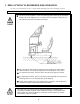
1 . PRECAUTIONS TO BE HEEDED FOR OPERATION In order to prevent accidents, be sure to comply with the following points before and during operation. PRECAUTIONS TO BE HEEDED FOR OPERATION BEFORE STARTING THE OPERATION In order to avoid accidents, check the following before starting the operation: Check if all of the adjusters are in contact with the surface. If they are not, the cabinet can move and cause an accident. Do not climb on the product. Climbing on the product can cause falling down accidents.
PRECAUTIONS TO BE HEEDED DURING OPERATION To avoid injury and accidents, those who fall under the following catagories are not allowed to play the game: * Intoxidated persons * Those who have high blood pressure or heart problems. * Those who have experienced muscle convulsion or loss of consciousness when playing video games, etc. * Persons susceptible to motion sickness. * Persons whose acts runs counter to the products warning displays.
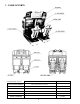
2 . NAME OF PARTS GAME SPECIFICATIONS WIDTH LENGTH HEIGHT ~ 1250 LBS. All measurements are in inches Weight-DURING SHIPPING WEIGHT BILLBOARD 64” X 27” X 24” 105 LBS. COCKPIT (PER SEAT) 33” X 66” X 61” 514 LBS. COIN CHUTE TOWER 12.5” X 18” X 23” 33 LBS. 66” X 68” X 85” 1172 LBS.
3 .
THE SHIPMENT METHOD DESCRIBED BELOW ONLY APPLIES TO ‘MODEL 3’ BOARDS CONTAINED IN THE FOLLOWING GAMES: LOST WORLD, VIRTUA FIGHTER 3, SUPER GT, SEGA BASS FISHING, STRIKER 2 HARLEY DAVIDSON, RALLY 2 !!NEVER SHIP MODEL 3 GAME BOARDS OUTSIDE OF CAGE!! CARTON BOX 601-8928 (1) Used for transporting the GAME BOARD. {SUPPLIED WITH YOUR GAME} DO NOT SHIP GAME BOARD WITHOUT THIS BOX AS IT MAY DAMAGE THE GAME BOARD AND VOID YOUR WARRANTY.
4 . ASSEMBLING AND INSTALLATION Assembling should be performed as per this manual. Since this is a complex machine, erroneous assembling may cause damage to the machine, or malfunctioning to occur. When assembling, be sure to perform work by plural persons. Depending on the assembly work, there are some cases in which performing the work by a single person can cause personal injury or parts damage.
1 Place the two cockpits side by side. Position the 1P cabinet, which has the power cord at the left hand side, as shown in the diagram. 2 Install the coin chute tower in between the two cabinets. Open the coin chute door and cashbox door to secure with the 4 hex bolts from are fastened temporarily.
2 ASSY OF THE BILLBOARD Due to its large size, it is very difficult for one person alone to install the billboard, Make sure 2 or more persons are available to perform this work. Attempting to perform the installation alone can cause an accident. 1 Mount Billboard on tbothcabinets and secure with the 4 hexgaonal bolts for each cabinet. 2 Connect all of the 4 connectors inside the Billboard box. 3 Install Wire Cover L&R with 5 screws for each.
3 SECURING IN PLACE (ADJUSTER ADJUSTMENT) Be sure to have all the Adjusters make contact with the surface. Unless the Adjusters come into contact with the surface, the Cabinet can move of itself, causing an accident. This machine has 8 each of casters and adjusters (shown below). When the installation position is determined, cause the adjusters to come into contact with the floor directly, make adjustments in a manner so that the casters will be raised approximately 5mm.
4 POWER SUPPLY Ensure that the power cord is not exposed on the surface (passage, etc.). If exposed, they can be caught and are susceptible to damage. If damaged, the cord can cause an electric shock or short circuit. Ensure that the wiring position is not in the customer's passage way or the wiring has protective covering. Connect the game to the power supply and turn on power to the game.
5 ASSEMBLING CHECK The TEST MENU allows for each part of the cabinet to be checked, the Monitor to be adjusted, and the coin and game related various functions to be performed.
SOUND TEST EFFECT : VOICE : B.G.M. : SPEAKER : BGM VOLUME LEVEL SOUND OFF SE_CHECK1 VO_30 BM_ADV1 VO_FRONT 9/15 In the TEST mode, selecting SOUND TEST causes the screen, on which sound related BD and wiring connections are tested, to be displayed. be sure to check if the sound is satisfactorily emitted from each of speaker and the sound volume is appropriate. >EXIT SELECT WITH SERVICE BUTTON PRESS TEST BUTTON TO EXIT C.R.T.
5 . PRECATIONS TO BE HEEDED WHEN MOVING THE MACHINE When moving the machine, be sure to pull out the plug from the power supply. Moving the machine with the plug as is inserted can damage the power cord and cause a fire or electric shock. When moving the machine on the floor, retract the Adjusters and ensure that Casters make contact with the floor. During transportation, pay careful attention so that Casters do not tread power cords.
6 . CONTENTS OF GAME The following explanations apply to the case the product is functioning satisfactorily. Should there be any moves different from the following contents, some sort of faults may have occured. Immediately look into the cause of the fault and eliminate the cause thereof to ensure satisfactory operation. During the Advertise mode, the Billboard’s Decoration Lamp lights up periodically. When the machine is energized, the Billboard’s Fluorescent Lamp is always lit.
WHEN PLAYING IN TH ECHAMPIONSHIP MODE Note: In the interactive play, CHAMPIONSHIP MODE can not be selected. 1 The car select mode appears. Select from among 6 types. Depending on the type of car, your operating sensation may somewhat vary. Choose the desired car by turning the Steering Wheel, and confirm with the Accelerator Pedal. 2 TRANSMISSION SELECT mode appears. Turn the Steering Wheel and select either AT (AUTOMATIC) or MT (MANUAL, 4 SHIFTS), and confirm with pedal. 3 The NAME ENTRY MODE appears.
4 On the upper left portion of the screen, total time & lap time are displayed. The remaining time is shown at the top center and navigation icon is seen at the loer part of the top center. on the upper right-hand side, the present player’s position as well as the stage’s top 3 times are displyed. the lower left portion shows tachometer and shift speed. the lower right-hand portion indicates the selected car and the driver’s name entered. 5 After game start, time decreases.
WHEN PLAYING IN THE PRACTICE MODE 1 The Course Select mode appears. Turn the Steering Wheel to select and confirm with pedal. In case of communication play, the course is selected by majority. 2 The Car Select Mode appears. Select from among the 6 types. Depending on the type of car, your operating sensation may somewhat vary. Select the desired car with the Steering Wheel. Step on the Accelerator to confirm. 3 The Transmission Select Mode appears.
4 The NAME ENTRY MODE appears. Turn the Steering Wheel to choose input characters, and confirm with pedal. After inputing the 3 characters, game start 5 On the upper left portion of the screen, total time & lap time are displayed. The remaining time is shown at the top center and navigation icon is seen at the loer part of the top center. on the upper right-hand side, the present player’s position as well as the stage’s top 3 times are displyed. the lower left portion shows tachometer and shift speed.
7 . EXPLANATION OF TEST AND DATA DISPLAY By operating the switch unit, periodically perform the tests and data check. When installing the machine intitally or collecting cash, or when the machine does not function correctly, perform checking in accordance with the explanations given in this section. The following shows tests and modes that should be utilized as applicable. When you enter the test mode, the Handlebar and Bike Body are unlocked. Do not lean against the BikeBody when you press the test button.
7 - 1 SWITCH UNIT AND COIN METER Never touch places other than those specified. Touching places not specified can cause electric shock and short circuit. Adjust to the optimum sound volume by considering the environmental requirements of the installation location. If the COIN METER and the game board are electrically disconnected, game play is not possible. Open COIN CHUTE DOOR, and the switch unit shown appears.
7 - 2 TEST MODE This mainly checks if the operation of the game BD is accurate, and allows for COIN ASSIGNMENTS/GAME ASSIGNMENTS setting and Projector adjustments. The Following FIGURES/TABLES show the factory recommended settings. TEST MENU MEMORY TEST 1 Push the TEST BUTTON to cause the following TEST MENU to appear: 2 By pushing the SERVICE BUTTON, bring the “>” mark to the desired item and press the TEST BUTTON. This will select the item’s test.
7 - 4 STEERING REACTION TEST This test allows Steering Wheel reaction mechanism to be tested and eaction force to be set. Press the Service Button to STEERING REACTION TEST bring the arrow to the desitred item to be selected, and press the CENTERING RIGHT LEFT FORCE >EXIT OFF OFF OFF OFF Test Button to enter the selected item. CENTERING Press the Test Button or the Start Button to apply automatic centering to Steering Wheel. RIGHT The Steering Wheel turns up to the RIGHT maximum value.
7 -5 INPUT TEST Select INPUT TEST to have the screen shown below appear and to observe the status of each switch and the Control Panel’s each V.R. Value. Periodically check the status of each switch and V.R. on this screen. By pressing each switch, if the display onthe right-hand side of the name of each switch changes to ON from OFF, the SW and the wiring connections are satisfactory.
7 - 7 SOUND TEST SOUND TEST EFFECT : VOICE : B.G.M. : SPEAKER : BGM VOLUME LEVEL SOUND OFF SE_CHECK1 VO_30 BM_ADV1 VO_FRONT 9/15 >EXIT This enables sound used in the game to be checked. Sound related memory and each speaker are checked. EFFECT: Sound effects during game. VOICE: Voice of announcement and naration. SPEAKER: SE speaker check. Checking front/back and left/right is possible. BGM VOLUME LEVEL: BGM sound level. 0/15 (low)~15/15 (high) SELECT WITH SERVICE BUTTON PRESS TEST BUTTON TO EXIT FIG.
7 - 9 GAME ASSIGNMENTS Selecting the GAME ASSIGNMENTS in the MENU mode causes the present game settings to be displayed and also the game settings changes (game difficulty, etc.) can be made. Each item displays the following content. SETTING CHANGE PROCEDURE Setting changes cannot be stored unless the TEST BUTTON is pressed while the arrow is on EXIT. 1 Press the SERVICE BUTTON to move the “>” to the desired item. 2 Choose the desired setting change item by using the TEST BUTTON.
7 - 10 COIN ASSIGNMENTS The “COIN ASSIGNMENTS” mode permits you to set the start number of credits, as well as the basic numbers of coins and credits. This mode expresses “how many coins correspond to how many credits.” SETTING CHANGE PROCEDURE Setting changes cannot be stored unless the TEST BUTTON is pressed while the arrow is on EXIT. 1 Press the SERVICE BUTTON to move the arrow to the desired item. 2 Choose the desired setting change item by using the TEST BUTTON.
TABLE 7.
MANUAL SETTING Selecting MANUAL SETTING in the COIN ASSIGNMENTS mode displays the following screen. MANUAL SETTING COIN TO CREDIT 1 COIN BONUS ADDER NO BONUS ADDER 1 1 CREDIT 2 COIN CHUTE #1 MULTIPLIER 1 COIN COUNTS AS 1 COIN COIN 1 2 3 CREDIT 1 2 3 4 4 5 5 6 6 7 7 8 8 9 9 COIN CHUTE #2 MULTIPLIER 1 COIN COUNTS AS 1 COIN COIN 1 2 3 CREDIT 1 2 3 4 4 5 5 6 6 7 7 8 8 9 9 3 >EXIT SELECT WITH SERVICE BUTTON AND PRESS TEST BUTTON FIG. 7.10sb MANUAL SETTING 1 Determines Coin/Credit setting.
7 - 11 BOOKKEEPING Choosing BOOKKEEPING in the MENU mode displays the data of operating status up to the present are shown on 2 pages. Press the TEST BUTTON to proceed to PAGE 2/2.
8. HANDLE MECHA In order to prevent an electric shock and short circuit, be sure to turn power off before performing work by touching the interior parts of the product. Be careful so as not to damage wirings. Damaged wiring can cause an electric shock or short circuit accident. In the test mode, if the steering whell’s VR variations are not within the allowable range, the VR installation position adjustments or VR replacement is needed.
8 - 2 REPLACING AND ADJUSTING THE HANDLE’S VR Never touch places other than those specified. Touching places not specified can cause electric shock and/or short circuit. After the replacement or adjustment of the VR, be sure to set the variable value of the VR in the test mode’s Volume Setting. REPLACING THE VOLUME 1 Turn off the power. 2 Disconnect the connector. 3 Take out the 2 screws which secure the volume Bracket and remove the Volume Bracket.
8 - 3 GREASING Never touch places other than those specified. Touching places not specified can cause electric shock and/or short circuit. After the replacement or adjustment of the VR, be sure to set the variable value of the VR in the test mode’s Volume Setting. Apply greasing to the Volume gear mesh portion every 3 months. For spray greasing, use Grease Mate (Part No. 090-0066).
9. SHIFT LEVER In order to prevent electric shock and short circuit, be sure to turn off the power before performing work on the interior parts of the product. Be careful not to damage wiring. Damaged wiring can cause electric shock or short circuit. Do not touch places other than those specified. Touching places other than those specified can cause an electric shock or short circuit accident.
9 - 2 SWITCH REPLACEMENT Each microswitch is secured with 2 screws. Remove the 2 screws and replace the Microswitch. After replacing the Switch, check to see if the switch is inputted as per Shift Lever operation in the Test Mode.
10. ACCEL & BRAKE(S) In order to prevent an electric shock and short circuit, be sure to turn power off before performing work by touching the interior parts of the product. Be careful so as not to damage wirings. Damaged wiring can cause an electric shock or short circuit accident. Do not touch places other than those specified. Touching places not specified can cause an electric shock or short circuit accident.
Check Volume values in the Test Mode. Since work is performed inside the energized cabinet, be very careful so as not to touch undesignated portions. Touching places not specified can cause an electric shock or short circuit. 1 Take out the 2 truss screws and remove the Front Cover from the Accel. & Brake unit. 2 Loosen the screw which secures the Potentiobase, and adjust the Volume Value by moving the Base. 3 Secure the Potentiobase. 4 Perform Volume setting in the Volume Setting Mode.
In order to prevent an electric shock and short circuit, be sure to turn power off before performing work byt ouching the interior parts of the product. Be careful so as not to damage wirings. Damaged wiring can cause an electric shock or short circuit accident. Do not touch places other than those specified. Touching places not specified can cause an electric shock or short circuit accident. Be sure to use designated grease. Using undesignated grease can cause parts damage.
11 . COIN SELECTOR HANDLING THE COIN JAM If the coin is not rejected when the REJECT BUTTON is pressed, open the coin chute door and open the selector gate. After removing the jammed coin, put a normal coin in and check to see that the selector correctly functions. CLEANING THE COIN SELECTOR 1 2 3 4 5 6 GATE The coin selector should be cleaned once every 3 months. When cleaning, follow the procedure below: Turn the power for the machine OFF. Open the coin chute door.
OPTIONAL DOLLAR BILL ACCEPTOR THE COIN DOOR ASSEMBLY USED ON RALLY 2 Twin Version COMES EQUIPPED TO ACCEPT A DOLLAR BILL ACCEPTOR. ALL NEEDED WIRING CONNECTIONS ARE CONVIENENTLY LOCATED INSIDE THE GAME FOR THIS APPLICATION.
43
12. MONITOR When performing such work as installing and removing the monitor, inserting and disconnecting the external connectors to and from monitor, be sure to disconnect the power connector (plug) before starting work. Proceeding the work without following this instruction can cause electric shock of malfunctioning. Using the monitor by converting it without obtaining a prior permission is not allowed. SEGA shall not be liable for any malfunctioning and accident caused by said conversion.
For the purpose of static prevention, special coating is applied to the CRT face of this product. To protect the coating, pay attention to the following points. Damaging the coating film can cause electric shock to the customers. For the caution to be heeded when clearing, refer to the Section of Periodic inspection Table. Do not apply or rub with a hard item (a rod with pointed edge, pen, etc.) to or on C.R.T. surfaces. Avoid applying stoickers, seals, etc. on the C.R.T. face.
46
13. REPLACEMENT OF FLUORESCENT LAMP AND LAMPS When performing the work, be sure to turn power off. Working with power on can cause an electric shock or short circuit accident. The Fluorescent Lamp, when it gets hot, can cause burns. Be very careful when replacing the Fluorescent Lamp. To perform work safely and securely, be sure to prepare a step which is in a secure and stable condition. Not using a step or using an unstable step can cause violent falling down accidents.
13 - 2 LAMP REPLACEMENT 1 Remove Wire Covers A and B 2 Disconnect the connector, take out the screw to remove the Lamp Unit, and replace the lamp.
14. PERIODIC INSPECTION TABLE The items listed below require periodic check and maintenance to retain the performance of this machine and ensure safe operation. Be sure to check once a year to see if Power Cords are damaged, the plug is securley inserted, dust is accumulated between the Socket Outlet and the Power Plug, etc. Using the product with dust as is accumulated can cause a fire or electrical shock. Periodically once a year, request the place of contact herin stated or the Distributer, etc.
15. TROUBLESHOOTING Should trouble occur, first check connector connections. PROBLEMS CAUSE COUNTERMEASURES With Main SW ON, no activation Power is not supplied. Plug in correctly Power supply/voltage is not correct. Make sure that power supply/voltage is correct. Check fuse. Remove the cause of overload and replace fuse AC main fuse causes the power to be cut off due to momentary overload. Operation is unsatisfactory Volume Setting Failure Perform Volume setting Adjust or replace V.R.
16. GAME BOARD In order to prevent an electrical shock, be sure to turn power off before performing work by touching the interior parts of the product. Be careful so as not to damage wirings. Damaged wiring can cause an electric shock or short circuit accident. Do not expose the Game BD, etc. without a good reason. In this product, setting changes are made during the test mode. The Game BD need not be operated. Use the Game BD, etc. as is with the same setting made at the time of shipment.
16 - 2 REPLACEMENT OF FUSE In order to prevent an electric shock, be sure to turn power off before performing work by touching the interior parts of the product. Be careful so as not to damage wirings. Damaged wiring can cause an electric shock or short circiut accident After eliminating the cause of the blowing of fuse, replace the fuse. Depending on the cause of the fuse blowing, using the fuse as is blown can cause generation of heat resulting in fire.
16 - 3 COMPOSITION OF GAME BOARD GAME BD SRT TWIN (833-13373) NOTE: THIS PICTURE IS FOR REFERENCE ONLY!! UNIT IS NOT TO BE OPENED. EXPOSING THE GAME BD FOR ANY REASON MAY VOID WARRANTY.
16 - 4 ERROR DISPLAY (DRIVE CONTROL BOARD) Be Careful so as not to damage wirings. Damaged wirings can cause an electric shock or short circuit accident. Do not touch places other than those specified. Touching places not specified can cause an electric shock or short circuit accident. If an irregularity occurs inthe Drive Control Board, etc., the ERROR message is shown ont he screen and the 7-SEG display ont he Drive Control Board. Take countermeasures in the manner corresponding to the ERROR message.
If ERROR display is shown on the screen, incline the Seat WITHOUT TURNING POWER OFF, and remove Back Lid B to check the 7-SEG display ont he Drive Control Board. At this time, if the power is turned off, each of the Er 23, 24, and 25 which could have occured during operation may not be displayed.
17. COMMUNICATION PLAY Before performing between-cabinets connection work, be sure to turn the Power SW OFF and unplug the power plug from the wall socket. Failure to observe this can cause electric shock and/or short circuit accidents. Perform assembling as shown in this manual. Erroneous assembling can cause electric shock accidents and malfunctioning. By linking 4 machines, up to 4 persons can play simultaneously.
1 To assemble your Rally 2 Twin Game locate the Left Cabinet (side with on/off switch), Cash Box Tower, and Right Side Cabinet. In the parts bag located in the cash box, locate the Opto Cable. this will be needed later, to connect together the opto connections on the rear of the Cash Box Tower. The hardware needed to assemble your Rally 2 Twin game has been threaded into the proper holes. This was done to insure the bolts thread properly into the T nuts in the Cabinet.
58
17 - 3 SETTING FOR COMMUNICATION PLAY During communication play, if communication is interrupted due to a certain cause, ERROR MESSAGE will be displayed, then NETWORK check mode appears on the screen automatically. Cause all of the seats to enter the Test Mode and change the GAME ASSIGNMENTS of each seat for communication play. Refer to the section on Explanation of Test and Data display for changing procedure. 1 Press the TEST button to enter the test mode and choose “GAME ASSIGNMENTS”.
18.
DESIGN RELATED PARTS 61
19.
TOP ASSY SEGA RALLY2 TWIN ITEM NO. PART NO.
ASSY BILLBOARD (SRT-0200) ITEM NO. PART NO.
ASSY BILLBOARD BOX (SRT-0202) ITEM NO. PART NO.
ASSY LIGHT COVER (SRT-0206) ITEM NO. PART NO.
LAMP UNIT (SRT-0213) ITEM NO. PART NO.
ASSY FL BOX L (SRT-0215) ITEM NO. PART NO.
ASSY FL BOX R (SRT-0227) ITEM NO. PART NO.
ASSY COINCHUTE TOWER (SRT-0300) 70
ASSY COINCHUTE TOWER (SRT-0300) ITEM NO. PART NO. DESCRIPTION 1 2 3 4 5 10 11 12 13 101 102 103 104 105 SRT-0350 SPG-0301 DYN-0302Y DP-1167 BOX-CASH DYN-0305 105-5202 SPG-0302 SPG-0303 220-5237-92 220-5412 220-5412-01 220-5574 220-5575 SW UNIT COIN CHUTE TOWER COIN METER BRKT TNG LKG CASH BOX TOWER BRKT HOLE COVER WIRE BOX WIRE BOX LID ASSY C.C.
SW UNIT (SRT-0350) ITEM NO. PART NO.
ASSY COCKPIT 1P (SRT-10001) ASSY COCKPIT 2P (SRT-11001) 73
ASSY COCKPIT 1P (SRT-10001) ASSY COCKPIT 2P (SRT-11001) ITEM NO. PART NO.
ASSY MONITOR COVER L 1P (SRT-1030) ASSY MONITOR COVER L 2P (SRT-1040) ITEM NO. PART NO.
ASSY MONITOR COVER R 1P (SRT-1035) ASSY MONITOR COVER R 2P (SRT-1045) ITEM NO. PART NO.
ASSY SPEAKER (SPG-1100) ITEM NO. PART NO.
ASSY CONTROL PANEL TWIN EXP (SRT-12001-01) 78
ASSY CONTROL PANEL TWIN EXP (SRT-12001-01) ITEM NO. PART NO.
ASSY HANDLE MECHA (SPG-2500) 80
ASSY HANDLE MECHA (SPG-2500) ITEM NO. PART NO.
ASSY 4 SPEED SHIFTER (SPG-2150) 82
ASSY 4 SPEED SHIFTER (SPG-2150) ITEM NO. PART NO.
ASSY VIRTUAL BUTTON TWIN (SRT-1290) ITEM NO. PART NO.
ASSY MAIN BASE 1P (SRT-20001) ASSY MAIN BASE 2P (SRT-21001) 85
ASSY MAIN BASE 1P (SRT-20001) ASSY MAIN BASE 2P (SRT-21001) ITEM NO. PART NO.
AC UNIT MAIN (SRT-0400) TEM NO. PART NO. DESCRIPTION 1 101 102 103 105 107 108 SPG-0401X 600-5843-25 280-5134-6N34 LOCAL PURCHASE 509-5453-91-V-B 280-0417 211-5479 AC BRKT CA & PLUG ASSY 15A W/F-L=2.
ASSY BASE BOX (SRT1-1500) ITEM NO. PART NO.
MAIN BASE (SRT0-1501) ITEM NO. PART NO.
ASSY SEAT TWIN 1P (SRT-1600) ASSY SEAT TWIN 2P (SRT-1700) 90
ASSY SEAT TWIN 1P (SRT-1600) ASSY SEAT TWIN 2P (SRT-1700) ITEM NO. PART NO.
ASSY WOOFER (STC-1650) ITEM NO. PART NO.
ASSY HAND BRAKE (SRT-2200) 93
ASSY HAND BRAKE (SRT-2200) ITEM NO. PART NO.
ASSY ACCEL&BRAKE (SPG-2200) 95
ASSY ACCEL&BRAKE (SPG-2200) ITEM NO. PART NO.
ASSY MAIN BD BASE (SRT-4400) ITEM NO. PART NO.
ASSY ELEC BASE (SRT-4500) NOTE: ITEM #103 MAY BE INSTALLED PERPENDICULAR TO THIS BOARD TO ALLOW ROOM FOR DRIVE BOARDS.
ASSY ELEC BASE (SRT-4500) ITEM NO. PART NO. DESCRIPTION 1 2 3 101 102 103 105 106 107 108 SRT-4501 SRT-4700 105-5317 560-5359 838-10801 838-11650-38 838-11651-91 839-0542 LOCAL PURCHASE 839-0542-02 WOODEN BASE ELEC ASSY SHIELD CASE MPEG SHIEDL CASE BRKT MPEG PWR XFMR 100V 6.5A 12.5V 6Ax2 CONN BD B EQ.
ASSY SHIELD CASE MPEG (SRT-4700) ITEM NO. PART NO.
ASSY DRIVE BD TWIN (SRT-4550) ITEM NO. PART NO.
Come see Sega GameWorks Service Department’s Homepage