www.sauservice.com 1ST PRINTING JUNE ‘04 ® Twin Type Owner’s Manual SEGA AMUSEMENTS USA, INC. MANUAL NO.
VISIT OUR WEBSITE!
BEFORE USING THE PRODUCT, BE SURE TO READ THE FOLLOWING: To maintain the safety: To ensure the safe usage of the product, be sure to read the following before using the product. The following instructions are intended for the users, operators and the personnel in charge of the operation of the product. After carefully reading and sufficiently understanding the warning displays and cautions, handle the product appropriately.
Specification changes (removal of equipment, conversion and addition) not designated by SEGA are not allowed. The parts of the product include warning labels for safety, covers for personal protection, etc. It is very hazardous to operate the product by removing parts and or modifying the circuits. Should doors, lids and protective parts be damaged or lost, refrain from operating the product, and contact where the product was purchased from or the office herein stated.
TABLE OF CONTENTS BEFORE USING THE PRODUCT, BE SURE TO READ THE FOLLOWING: TABLE OF CONTENTS INTRODUCTION OF THE OWNER’S MANUAL 1. HANDLING PRECAUTIONS ....................................................................................... 2. PRECAUTIONS CONCERNING INSTALLATION LOCATION ............................... 3. OPERATION .................................................................................................................. 4. NAME OF PARTS ..............................................
Installation Space Height Width Length Weight Power, maximum current MONITOR SPECIFICATIONS : : : : : : 74.3 inches width X 73 inches 71.
DEFINITION OF LOCATION MAINTENANCE MAN AND SERVICEMAN WARNING! Non-technical personnel who do not have technical knowledge and expertise should refrain from performing such work that this manual requires the location's maintenance man or a serviceman to carry out, or work which is not explained in this manual. Failing to comply with this instruction can cause a severe accident such as electric shock.
CONCERNING THE STICKER DISPLAY CONCERNING WARNING DISPLAYS SEGA product has Stickers describing the product manufacture No. (Serial No.) and Electrical Specifications. Also it has a Sticker describing where to contact for repair and for purchasing parts. When inquiring about or asking for repair, mention the Serial No. and Name of Machine indicated on the Sticker. The Serial No. indicates the product register. Identical machines could have different parts depending on the date of production.
1. HANDLING PRECAUTIONS When installing or inspecting the machine, be very careful of the following points and pay attention to ensure that the player can enjoy the game safely. Non-compliance with the following points or inappropriate handling running counter to the cautionary matters herein stated can cause personal injury or damage to the machine. WARNING! ● Before performing work, be sure to turn power off. Performing the work without turning power off can cause an electric shock or short circuit.
STOP IMPORTANT! ● For the IC board circuit inspections, only the logic tester is allowed. The use of a multiple-purpose tester is not permitted, so be careful in this regard. ● The Projector is employed for this machine. The Projector's screen is susceptible to damage, therefore, be very careful when cleaning the screen. For details, refer to PROJECTOR. ● Static electricity from your body may damage some electronics devices on the IC board.
2. PRECAUTIONS CONCERNING INSTALLATION LOCATION WARNING! This product is an indoor game machine. Do not install it outside. Even indoors, avoid installing in places mentioned below so as not to cause a fire, electric shock, injury and or malfunctioning. ● Places subject to rain or water leakage, or places subject to high humidity in the proximity of an indoor swimming pool and or shower, etc. ● Places subject to direct sunlight, or places subject to high temperatures in the proximity of heating units, etc.
Operation Area WARNING! STOP IMPORTANT! ● For the operation of this machine, secure a minimum area of 74.3 in. (W)×73 in. (D). In order to prevent injury resulting from the falling down accident during game play, be sure to secure the minimum area for operation. ● Be sure to provide sufficient space so as to allow this product's ventilation fan to function efficiently. To avoid machine malfunctioning and a fire, do not place any obstacles near the ventilation opening.
3. OPERATION PRECAUTIONS TO BE HEEDED BEFORE STARTING THE OPERATION To avoid injury and trouble, be sure to constantly give careful attention to the behavior and manner of the visitors and players. In order to avoid accidents, check the following before starting the operation: WARNING! ● To ensure maximum safety for the players and the customers, ensure that where the product is operated has sufficient lighting to allow any warnings to be read.
WARNING! CAUTION! ● Do not put any heavy item on this product. Placing any heavy item on the product can cause a falling down accident or parts damage. ● Do not climb on the product. Climbing on the product can cause falling down accidents. To check the top portion of the product, use a step. ● To avoid electric shock, check to see if door & cover parts are damaged or omitted.
WARNING! ● To avoid electric shock and short circuit, do not allow the customers to unplug the power plug without a justifiable reason. ● This product is intended for 1 Player only per seat. Playing the game by 2 or more Players riding on the seat together can cause falling down and collision accidents by striking head, hand, or elbow. ● Caution lookers-on so as not to touch the operating unit while in play. Failure to observe this may cause bodily contact with the player and trouble between the customers.
PRECAUTIONS TO BE HEEDED BEFORE STARTING THE OPERATION (CARD SYSTEM) STOP IMPORTANT! When an unjust act is performed, no written data is backed up mechanically. The following acts may be judged to be unjust acts. Since it also becomes a defect of operation and the cause of parts damage, caution the player not to perform the following acts.
4. NAME OF PARTS FIG. 4 a OVERVIEW ***Note: Actual Main unit may differ from image. FIG. 4 b REAR VIEW TABLE 4 Dimensions and Weights CABINET 1 CABINET 2 ASSY POP When assembled Width x Length x Height 44 in x 68 in x 71.75 in 36.75 in x 68 in 30 in x 22 in 80.75 in x 68 in 9 x 71.75 in x 14 in x 71.75 in Weight 865 LB 700 LB 1 LB 1565 LB www.seuservice.
5. ACCESSORIES When transporting the machine, make sure that the following parts are supplied. Magnetic cards for the recording of play results, and cleaning kits for cleaning the head of the card reader/writer are sold separately. Subsequent purchases of these items can be made by contacting the office listed on this Owner's Manual or the dealer from whom the product was originally purchased. Be sure to provide the part number(s), name(s), and required number of items.
The following Table 5b lists the parts that are separately marketed but are necessary when booting this product's software. When having unpacked the shipping crate, make sure that all the parts in this Table 5b are in the crate. If not so, contact where you have obtained the product. TABLE 5 b (XKT-0833 : GD-ROM DRIVE KIT) GD-ROM DRIVE XKT-0833 GD-ROM DRIVE CARTON BOX (1) Device that loads the software in a GD-ROM disc. see 5 of Section 6. Used for transporting the GD-ROM DRIVE. See FIG. 5 b.
HOW TO USE THE CARTON BOX (GD-ROM DRIVE) STOP IMPORTANT! When you want to order for replacing or repairing service of the GD-ROM drive that is used by the product, pack it in a carton box as instructed below, and then deliver the carton box to a service agent. If you do not observe the instruction, your order may not be accepted or may be charged additionally. If you handle the GD-ROM drive differently from the following instructions, its components may be damaged.
6. ASSEMBLING AND INSTALLATION WARNING! CAUTION! ● Perform assembly work by following the procedure herein stated. Failing to comply with the instructions can cause electric shock hazard. ● Perform assembling as per this manual. Since this is a complex machine, erroneous assembling can cause an electric shock, machine damage and or not functioning as per specified performance. ● When assembling, be sure to use plural persons.
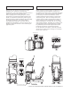
Tools such as a Phillips type screwdriver, wrench, socket wrench and Ratchet Handle are required for the assembly work. 24mm WRENCH Phillips type screwdriver 1 SOCKET WRENCH,RATCHET HANDLE INSTALLING THE POP AND POP CARD POP HOLDER SCREW (4) M6×16,w/flat and spring washers ● Install the POP Holder on the top of the Billboard by using the 4 screws. For performing this work, be sure to prepare a step. PHOTO 6. 1 a For performing work, prepare a step. * Note: Picture may differ from actual unit. www.
● Attach the POP to the POP Holder. Slide the POP cut-out so that the edges fit into the protruding portions of the POP Holder. POP POP CUT-OUT PHOTO 6. 1 b ● Attach Billboard Sash R with 2 Truss screws. ● Use 2 Truss screws to attach Billboard Sash L to the opposite side in the same manner. TRUSS SCREW (2) chrome BILLBOARD SASH R PHOTO 6. 1 c 15 www.seuservice.
2 WARNING! SECURING IN PLACE (ADJUSTER ADJUSTMENT) Make sure that all of the adjusters are in contact with the floor. If they are not, the cabinet can move and cause an accident. This product has 8 casters and 8 Adjusters. (FIG. 6. 2 a) When the installation position is determined, cause the adjusters to come into contact with the floor directly, make adjustments in a manner so that the casters will be raised approximately 5 mm from the floor and make sure that the machine position is level.
74.3 in. 6 in. Vent approx. 8 in. 73 in. 28 in. over FIG. 6. 2 e Provide ventilation space for the ventilation opening. Allow more than 28 in. of space for customer traffic. 17 www.seuservice.
3 INSTALLING THE GD-ROM DRIVE (SETTING GD-ROM DISC) STOP ● IMPORTANT! ● ● ● ● Carefully handle the GD-ROM drive so as not to contaminate the disc and the readout lens with stains and dust particles. Do not continue to use the scratched GD-ROM disc. The scratched GD-ROM disc may cause the system to malfunction. Set the GD-ROM disc onto the GD-ROM drive with its labeled side facing upward. The key chip is a precision device.
● Remove the 1 truss head screw that fixes the GD-ROM drive lid (DISC LID). And turn clockwise the lid to remove. TRUSS SCREW (1) M3×8 PHOTO 6. 3 b ● Set the GD-ROM disc onto the GD-ROM drive with its labeled side facing upward. ● Return the lid to its original place, and fix it with 1 truss head screw. Be careful not to fasten the screw too tightly. PHOTO 6. 3 c 19 TRUSS SCREW (1) M3×8 www.seuservice.
● Undo the lock on the side of the unit base and remove the Truss screws. ● Turn the knob to open the lock, and lower the seat towards the backrest. Slowly lower the backrest until it touches the floor to prevent damage to the seat components. Put a drop cloth on the floor to prevent damaging the surface of the seat components. DROP CLOTH TO PREVENT DAMAGE TO SURFACE OF PARTS UNLOCK TRUSS SCREW (2), black FIG. 6. 3 b * Note Figure may appear different then actual product.
● Connect the GD cable connector (for data communication) to the DIMM board. GD CABLE CONNECTOR PHOTO 6. 3 e ● Insert both the GD cable connector (for data communication) and the power cord connector into the GD-ROM drive. Be careful about an inserting direction in this instance. Make sure that the connectors are inserted firmly and completely. Secure the cable with the cord clamp. GD-ROM DRIVE GD Cable connector Power Cord connector Secure the cable. PHOTO 6. 3 f 21 www.seuservice.
KEY CHIP ● Paying attention to the direction of the Key Chip, insert it securely into the NAOMI DIMM Board Case. ● Place the Sticker on the side of the DIMM Board Case as shown in the figure. KEY CHIP PROJECTION STICKER Sticker Position FIG. 6. 3 c www.seuservice.
4 POWER SUPPLY, AND EARTH CONNECTION WARNING! ● Be sure to independently use the power supply socket outlet equipped with an Earth Leakage Breaker. Using a power supply without an Earth Leakage Breaker can cause a fire when electric leakage occurs. ● Ensure that the "accurately grounded indoor earth terminal" and the earth wire cable are available (except in the case where a power cord plug with earth is used). This product is equipped with the earth terminal.
5 TURNING POWER ON Turn on the AC unit's main switch to supply power to the unit. Once power is turned on, the fluorescent lamp lights up. The Start System Screen displays after a lapse of several seconds. It is followed by the screen that indicates that the network is currently being checked if the communication mode has been set. If there is a bad or improper communication connection, each screen will not proceed to the next, remaining on the currently Network Check Screen.
Each Check Screen is followed as below. Network Check Screen CHECKING NETWORK NOW Card Reader/Writer Check Screen ●When Card is left in the Card Reader/Writer; CARD R/W INITIALIZE... PLEASE GET CARD Motor Check Screen ● Remove the card. Screen does not change until the card is removed. KICKBACK INITIALIZE... ●When cleaning is required; PLEASE INSERT CLEANING CARD. ● Steering wheel will turn. Do not touch it. Insert the cleaning card. (See 7-2 HEAD CLEANING.) 25 www.seuservice.
6 ASSEMBLING CHECK In the TEST MODE, ascertain that the assembly has been made correctly and IC BD. is satisfactory (refer to Section 10). In the test mode, perform the following test: (1)MEMORY TEST Selecting the RAM TEST on the system test mode menu screen causes the on-board memory to be tested automatically. The game board is satisfactory if the display beside each IC No. shows GOOD.
(2)SOUND TEST SOUND TEST RIGHT SPEAKER OFF LEFT SPEAKER OFF In the system test mode, selecting SOUND TEST causes the screen (on which sound related BD and wiring connections are tested) to be displayed. Check if the sound is satisfactorily emitted from each speaker and the sound volume is appropriate. -> EXIT SELECT WITH SERVICE BUTTON AND PRESS TEST BUTTON (3)C.R.T. TEST In the system test mode menu, selecting C.R.T. TEST allows the screen (on which the monitor is tested) to be displayed.
(4)INPUT TEST Selecting the INPUT TEST on the game test mode menu screen causes the screen (on which each switch is tested) to be displayed. Press each switch. If the display beside each switch indicates "ON," the switch and wiring connections are satisfactory.
7. CARD READER/WRITER 7-1 SETTING DEDICATED CARDS STOP IMPORTANT! ● Be sure to use dedicated cards available for this product. Use of ones other than such dedicated cards may cause a malfunction or failure of the machine. ● Be sure to set the specified number of card in the specified orientation by using the specified procedure. Wrong setting of the cards may cause the machine to fail. ● This machine allows you to set up to 100 cards at a time. You must not set over 101 cards at a time.
● Remove the cover from the back of the dispenser. Be careful of instructions of the sticker. Dedicated Cards Remove the dispenser's cover. Be sure to set the cards orientation. Close the cover, and reinstall the dispenser. FIG. 7. 1 a ● Place the cards into the dispenser according to the instructions on the sticker annexed to the dispenser. Refer to the diagram shown on the sticker attached to the Dispenser and insert the cards into the Dispenser.
7-2 HEAD CLEANING STOP IMPORTANT! ● The unit enters Head Cleaning Mode when any of the following conditions are met: • At power-up if the Card Reader/Writer has operated 100 times or more • At power-up if the date has been updated • At boot time after performing Backup Data Clear ● Once the unit enters Head Cleaning Mode, follow the on-screen instructions and perform Head Cleaning. The unit will not exit Cleaning Mode (i.e. games may not be played) until head cleaning is complete.
7-3 CLEARING CARD JAMS STOP IMPORTANT! When attempting to perform this operation without powering down so that gameplay can be restored, exercise extreme caution. Machine parts may move unexpectedly when the power is ON. This may result in fingers being caught or severed and other injuries. Verify the Stay Lock on the top cover before attempting this procedure. If the top cover closes during the procedure, it may result in serious injury.
8. PRECAUTIONS WHEN MOVING THE MACHINE WARNING! CAUTION! ● When moving the machine, be sure to unplug the power plug. Moving the machine with the plug as is inserted can damage the power cord and cause fire and electric shock hazards. ● When moving the machine on the floor, retract the Adjusters and ensure that Casters make contact with the floor. During transportation, pay careful attention so that Casters do not tread power cords and earth wires.
In locations with low ceilings, remove the POP and POP Holder before moving the machine. * Note: Machine may be different then illustrated. FIG. 8 b Place the machine on casters. . www.seuservice.
9. GAME DESCRIPTION The following explanations apply to the case the product is functioning satisfactorily. Should there be any moves different from the following contents, some sort of faults may have occurred. Immediately look into the cause of the fault and eliminate the cause thereof to ensure satisfactory operation. When the power is connected, the fluorescent lamp in the FL box is always on. When in an advertising state, the screen displays the demonstration pictures and ranking data.
Game Overview The game is a car racing game with three different game modes: "Legend of the Street", "Time Attack" and "The Bunta Challenge". By connecting two units, you can also enjoy "Network Battle Game" play. The card system allows players to store information such as the car, wins/ loss records and car tune-up status on a special card. Legend of the Street ●Game Content & Rules Battle rival characters man to man on 9 different courses. Each checkpoint you pass adds time to the overall time limit.
● Vehicle Selection Screen: This screen isn't displayed if you've already purchased a card. ● Transmission Selection Screen: This screen isn't displayed if you've already purchased a card. ● Parts Course Selection Screen: If you're purchasing a card, select one of the Parts courses. These parts are then attached to your car when you accumulate enough points. 37 www.seuservice.
● Name Entry Screen: If you're purchasing a card, enter your name (driver's name) at the player name input screen. ● Mode Select Screen: Select "Legend of the Street" at the Mode Selection Screen. ● Course and Rival Character Selection Screens www.seuservice.
● Rival Character Scenes ● Battle (Race) ● Results Screen 39 www.seuservice.
● Tune Up Screen: Use your card to play and accumulate points you can put towards performance enhancing tune-ups. ● Continue Screen: Choose to continue or quit after rival character scenes. If you select "YES", nothing is recorded to the card and you can continue playing. If you select "NO", your game data is stored on your card and your game ends. www.seuservice.
Time Attack ● Game Content & Rules This is a race against time. The goal is to cross the finish line as quickly as you can. Direction, Time of Day and Weather can be selected for each of the nine courses - note that Happogahara and Akina (Snow) can only be set to Night. Each checkpoint you pass adds time to the overall time limit. When you cross the finish line, a password is displayed. (The password is not displayed when you don't use the card.
Before the Race [Champion Side] ● Battle Entry Challenge Request Screen When a challenge occurs before the start of the race (during selection phase): If the challenge occurs before the mode selection phase (during Car Selection etc), the Network Battle Race Information Screen is displayed directly before the selection phase. If the challenge occurs after the selection phase, selection is interrupted and the Network Battle Race Information Screen is displayed.
[Challenger Side] ● Network Battle Race Select Screen This screen asks if a new player wishes to enter a Battle Race. It only appears when a new player first inserts coins and the current player has opted to accept Battle Race challengers. ● Card Entry Screen When a Battle Race is established, the Card Entry Screen appears. A Battle can be raced even without a Card. If there is no Card, the game proceeds to the Car Selection and Transmission Selection Screens. The Course Selection Screen then appears.
● Continue Screen The winning player will receive victory points and will be allowed to continue play. The losing player will go to the Continue Screen. When the number of victories exceeds the set limit When a player's total number of victories exceeds the set limit, the player will be taken to the Continue Screen even if they win. (See Section "10-3 F".) Configuration When a Card is inserted, a number of options may be set.
● TIME DISPLAY Set the Time Display on the Race Screen. NORMAL: Standard time display. (Default setting) SIMPLE: Simplified time display. ● FORCED QUIT Force end of game during Legend of the Streets and Time Attack play. OFF: Disable force quit (Default setting) ON: Enable force quit. Press the Start and Change View Buttons simultaneously to end Game Over With “Legend of the Street”, “Time Attack” and “Network Battle Race” play, the Continue Screen appears after each race.
2. Player inserts credits at the Transfer Card Data Screen. 3. The old Card will be ejected. This Card can no longer be used. 4. When the "Card Data Transferred" message appears, the game will restart. The new Card is for exclusive use with the Initial D Ver. 3, and cannot be used with the previous versions, Initial D and Initial D Ver. 2. Limit on Card Use Each Card can be used for up to fifty plays, until Car Inspection time is reached.
Car Selections TOYOTA TRUENO GT-APEX [AE86] LEVIN GT-APEX [AE86] LEVIN SR [AE85] MR2 G-Limited [SW20] MR-S S EDITION [ZZW30] ALTEZZA RS-200 [SXE10] CELICA GT-FOUR [ST205] MAZDA RX-7 Type R [FD3S] RX-7 SPIRIT R Type A [FD3S] RX-7∞III [FC3S] RX-8 Type S [SE3P] ROADSTER S Special [NA6CE] ROADSTER RS [NB8C] SUBARU IMPREZA WRX STi Version VI [GC8] IMPREZA WRX STi [GDB] IMPREZA WRX type R STi Version V [GC8] NISSAN SKYLINE GT-R V-spec II [BNR32] SKYLINE GT-R V-spec II [BNR34] SKYLINE 25GT TURBO [ER34] SILVIA K'
"Legend of the Street" Rival Characters (EASY - Myogi) IGGY KENJI SHINGO LEVIN SR [AE85] 180SX TYPE X [RPS13] CIVIC SiR II [EG6] (NORMAL - Usui) TORU KAWAI MAYA&SIMONE ROADSTER S Special [NA6CE] SKYLINE 25GT TURBO [ER34] SILEIGHTY [RPS13] (HARD - Akagi) TWO GUYS FROM TOKYO SILVIA spec-R [S15] DANNY SILVIA Q's [S14] K. T.
10. EXPLANATION OF TEST AND DATA DISPLAY By operating the switch unit, periodically perform the tests and data check. When installing the machine initially or collecting cash, or when the machine does not function correctly, perform checking in accordance with the explanations given in this section. The following shows tests and modes that should be utilized as applicable. This product's basic system consists of the NAOMI 2 GD-ROM game board.
10-1 SWITCH UNIT AND COIN METER WARNING! STOP IMPORTANT! Never touch places other than those specified. Touching places not specified can cause electric shock and short circuit accidents. ● Adjust the sound to the optimum volume, taking into consideration the environmental requirements of the installation location. ● Removing the Coin Meter circuitry renders the game inoperable. SWITCH UNIT Open the coin chute door, and the switch unit shown will appear. The functioning of each SW is as follows: FIG.
10-2 SYSTEM TEST MODE STOP ● The contents of settings changed in the TEST mode are stored when the test mode is finished from EXIT in the menu mode. If the power is turned off before the TEST mode is finished, the contents of setting change become ineffective. ● Executing "BACKUP DATA CLEAR" in the SYSTEM TEST MODE does not clear the BOOKKEEPING data in the GAME TEST mode. ● Entering the TEST mode clears fractional number of coins less than one credit and BONUS ADDER data.
10-3 GAME TEST MODE STOP IMPORTANT! ● When changing the game configuration, changes will not take effect until the Game Test Mode has been completed. Be sure to exit the Game Test Mode properly after configuration changes. ● Do not configure the game in ways not described in this text. It is possible that the game will not function properly. A. GAME TEST MENU MODE Select GAME TEST MODE from the System Menu screen to display the Game Test Menu screen.
B. INPUT TEST Select INPUT TEST to display the following screen and check the status of input devices. This test should be used periodically to check that each input device is functioning correctly. GAME TEST MODE INPUT TEST STEERING ACCEL BRAKE GEAR POSITION START CHANGE VIEW SERVICE TEST XXH XXH XXH N OFF OFF OFF OFF PRESS TEST AND SERVICE BUTTON TO EXIT FIG. 10.
C. OUTPUT TEST Select OUTPUT TEST to display the following screen and check the status of each lamp. This test should be used periodically to check that the lamps are functioning correctly. GAME TEST MODE OUTPUT TEST ->START BUTTON CHANGE VIEW BUTTON PRESS TEST BUTTON TO EXIT FIG. 10. 3 c OUTPUT TEST Screen The cursor toggles automatically between START Button and CHANGE VIEW Button, and each lamp lights up. Move the cursor to EXIT and press the TEST Button to return to the Game Test Menu screen. www.
D. FORCE FEEDBACK CAUTION! If you select FORCE FEEDBACK, the STEERING will rotate automatically when you press the TEST Button. The STEERING will also rotate automatically during FORCE TEST. Make sure that no one is touching the STEERING before running these tests as contact may cause injury. When you select "FORCE FEEDBACK", a connection test runs and the STEERING rotates. When the connection check completes, a screen similar to the one below is displayed, and you may adjust the STEERING resistance.
E. INPUT ASSIGNMENTS Select INPUT ASSIGNMENTS to display the following screen. GAME TEST MODE INPUT ASSIGNMENTS STEERING: XXX (DEFAULT = 0) ACCEL : XXX (DEFAULT = 0) BRAKE : XXX (DEFAULT = 0) DEFAULT SETTING -> EXIT SELECT WITH SERVICE BUTTON AND PRESS TEST BUTTON FIG. 10. 3 ea INPUT ASSIGNMENTS Screen You can adjust each of the menu items by moving the cursor to the menu item and pressing the TEST Button. Return all settings to the default settings with DEFAULT SETTING.
● ACCEL: Make adjustments to ACCEL Press the TEST Button to display the following screen. Adjust the distance between "0" displayed and the "^" mark equally so that when your foot is off the ACCEL pedal, the "0" on the left is aligns with the "^" above MIN and when you press the ACCEL pedal down all the way, the "0" on the right is aligns with the "^" mark above MAX. Move the cursor to RIGHT and press the TEST Button to move "0" to the right. Each press of the TEST Button moves "0" slightly to the right.
F. GAME ASSIGNMENTS Select GAME ASSIGNMENTS to display the current game settings and make changes. GAME TEST MODE GAME ASSIGNMENTS GAME DIFFICULTY DEFALT VIEW SEAT NUMBER CARD R/W ->EXIT NORMAL DRIVER NO DEFINED ON SELECT WITH SERVICE BUTTON AND PRESS TEST BUTTON FIG. 10. 3 f GAME ASSIGNMENTS Screen The GAME DIFFICULTY and CONTINUE menu items can be set only when the SEAT NUMBER is set to either 1 or NO DEFINED. The VS LIMIT OF WIN menu item can be set only when the SEAT NUMBER is set to 1.
Changes to settings are not enabled until Test Mode is exited. After changing settings, be sure to exit Test Mode. After changing the settings, select EXIT and press the TEST Button to return to the Game Test Menu screen. G. CARD R/W TEST STOP Clean the card reader/writer periodically. IMPORTANT! Test the functionality of or clean the CARD R/W (read/writer). The CARD R/W should be tested and cleaned periodically.
Depending on the R/W running mode, one of the following is displayed in "*****" in "CARD R/W STATUS : *****": READY ........ Now waiting (Clear to Send Command) INITIAL .......Now initializing (Not Clear to Send Command) CLEAN ........Now cleaning (Not Clear to Send Command) GET ..............Cards are being taken out from the dispenser (Not Clear to Send Command) SAVE ............Sample data is saved onto the card (Not Clear to Send Command) LOAD ...........
CLEANING PROCESS Cleaning refers to the optional cleaning of the heads on the CARD R/W. Refer to section <7-2> Head Cleaning for details on the use of the cleaning card. ● Select "CLEANING" and press the TEST Button. ● If the CARD R/W is not initialized, it will be initialized first. :INITIALIZE is displayed. ● The following message appears to show that the R/W is ready for insertion of the cleaning card: -- PLEASE INSERT CLEANING CARD -● Insert the cleaning card into the R/W.
H. CLOSE SETTING Select CLOSE SETTING to display the following screen. Change the setting for the time when the store closes. The game will be unusable for card play starting 15 minutes before the time you set until 6:00 AM the next morning. GAME TEST MODE CLOSE SETTING SCHEDULE TYPE : DAY SETTING -> EXIT SELECT WITH SERVICE BUTTON AND PRESS TEST BUTTON FIG. 10. 3 ha CLOSE SETTING Screen You can set SCHEDULE TYPE to DAY, WEEK or OFF. Press the TEST Button to select the item.
● WEEK: Set a different store close time for each day of the week GAME TEST MODE CLOSE SETTING SUN MON TUE WED THU FRI SAT : : : : : : : 24:00 24:00 24:00 24:00 24:00 24:00 24:00 -> EXIT SELECT WITH SERVICE BUTTON AND PRESS TEST BUTTON FIG. 10. 3 hc CLOSE SETTING (WEEK) Screen Set the store closing time for each day of the week. When you press the SERVICE Button, the "hour" display will begin to flash. Press the TEST Button to select any hour from "19" to "26".
I. BOOKKEEPING Select BOOKKEEPING to display the following screens of operating status data. Each time the TEST Button is pressed, the ensuing page appears. Pressing the TEST Button while the 5/5 page is displayed causes the Game Test Menu to return on the screen.
GAME TEST MODE BOOKKEEPING 2/8 GAME / LEGEND OF THE STREET MYOGI-1 MYOGI-2 MYOGI-3 USUI-1 USUI-2 USUI-3 0 0 0 0 0 0 AKAGI-1 AKAGI-2 AKAGI-3 0 0 0 AKINA-1 AKINA-2 AKINA-3 AKINA-4 AKINA-5 0 0 0 0 0 PRESS TEST BUTTON TO CONTINUE FIG. 10. 3 i b BOOKKEEPING (2/8) Screen Press the TEST Button to move to screen 3/8 of BOOKKEEPING.
GAME TEST MODE BOOKKEEPING 4/8 GAME / TIME ATTACK MYOGI 0 USUI 0 AKAGI 0 AKINA 0 IROHAZAKA 0 AKINA SNOW 0 HAPPOGAHARA 0 SHOMARU 0 TSUCHISAKA 0 PRESS TEST BUTTON TO CONTINUE FIG. 10. 3 i d BOOKKEEPING (4/8) Screen ● GAME/TIME ATTACK: Displays the number of times each course was selected in TIME ATTACK mode Press the TEST Button to move to screen 5/8 of BOOKKEEPING.
Press the TEST Button to move to screen 6/8 of BOOKKEEPING. GAME TEST MODE BOOKKEEPING 6/8 GAME / BUNTA CHALLENGE MYOGI 0 USUI 0 AKAGI 0 AKINA 0 HAPPOGAHARA 0 IROHAZAKA 0 SHOMARU 0 TSUCHISAKA 0 TRANCEMISSION SELECT AUTOMATIC MANUAL 0 0 PRESS TEST BUTTON TO CONTINUE FIG. 10. 3 i f BOOKKEEPING (6/8) Screen ●GAME/BUNTA CHALLENGE: ●TRANSMISSION SELECT: Displays number of times each course has been selected for the Bunta Challenge.
Press the TEST Button to move to screen 8/8 of BOOKKEEPING. GAME TEST MODE CAR SELECT BOOKKEEPING 8/8 INTEGRA 0 S2000 0 LANCER EVO3 0 LANCER EVO4 0 LANCER EVO7 0 RX-7(FD3S1) 0 RX-7(FD3S6) 0 RX-7(FC3S) 0 ROADSTER(NA6C) 0 ROADSTER(NB8C) 0 IMPREZA(GC8S6) 0 IMPREZA(GDB) 0 IMPREZA(GC8S5) 0 CAPPUCCINO 0 SKYLINE 25GT(ER34) 0 LANCER EVO5 0 LANCER EVO6 0 RX-8(SE3P) 0 PRESS TEST BUTTON TO EXIT FIG. 10.
J. BACKUP DATA CLEAR Delete all BOOKKEEPING screen data. Use BACKUP DATA CLEAR in the SYSTEM TEST MODE to delete data about coin/credit collection. Deleting this data does not affect the game settings or other data stored by the game. Deleting this data will delete the data showing how many times the CARD R/W was used. After deleting the data, the CARD R/W automatically enters Head Cleaning mode. Refer to section <7-2> Head Cleaning for more information about head cleaning.
11. CONTROL PANEL WARNING! CAUTION! STOP ● In order to prevent an electric shock and short circuit, be sure to turn power off before performing work by touching the interior parts of the product. ● Be careful not to damage the wires. Damaged wires may cause electric shock or short circuit or present a fire risk. ● Do not touch undesignated places. Touching places not designated can cause electric shock or short circuit. ● This work should be performed by the Location's Maintenance Man or Serviceman.
11-1 REMOVING THE CONTROL PANEL Poor handle response/lack of response when adjusting the Volume in Test Mode may be caused by faulty Volume alignment and/or a damaged Volume. Follow the instructions below to adjust the gear alignment and/or replace the Volume. If the Volume Shaft is rotating within its normal area of mobility, there is little chance the Volume can be damaged by rotating the handle as far as possible to the left/right. With the handle in the center position, i.e.
11-2 ADJUSTING/REPLACING THE VOLUME ADJUSTMENT PROCEDURE ● Loosen the 2 screws that secure the VR Bracket and move the VR Bracket to adjust the angle and condition of the gear alignment. ● Keeping the handle straight, align the gears so that the direction of the D Cut side of the Volume Shaft matches that shown in the diagram. ● Tighten the 2 screws and secure the VR Base. FIG. 11. 2 a ● After making adjustments, use the Volume Setting Screen to set the Volume (refer to 10-3E).
REPLACEMENT PROCEDURE This procedure requires the following tools: Philips screwdriver for the M4 screws, 2 mm hexagonal wrench, 11—12mm monkey wrench, nipper, cutter, wire stripper, soldering iron and industrial dryer. ● Remove the connectors. ● Remove the 2 screws securing the VR Bracket and remove the entire Bracket and Volume. VR BRACKET CONNECTOR (1) RED 3P SCREW (2) M4×10, w/flat & spring washers PHOTO 11. 2 ● Loosen the 2 hexagon socket screws on the Gear Holder and remove the Gear Holder.
11-3 GREASING WARNING! CAUTION! STOP IMPORTANT! ● Grease is inflammable and must never be close to fire. ● Grease may be apt to be erroneously used or drunk, and must not be placed in a location where children can access. ● Grease does harm to your body if you aspirate it. Do not perform any work related to grease in a location where ventilation is insufficient. ● If grease enters an eye, eye irritation may be caused.
12. SHIFT LEVER In the Test Mode, if the SHIFT LEVER's SW can not be inputted satisfactorily, replace the Switch. Apply greasing to the Mechanism's sliding portion once every 3 months. When performing the above work, remove the Shift Lever Unit. WARNING! ● Before starting to work, ensure that the Power SW is OFF. Failure to observe this can cause electric shock and short circuit hazards. ● Use care so as not to damage wirings. Damaged wiring can cause electric shock and short circuit hazards.
13. ACCELERATOR & BRAKE ● ● WARNING! ● ● ● STOP Before starting to work, ensure that the Power SW is OFF. Failure to observe this can cause electric shock or short circuit. Use care so as not to damage wirings. Damaged wiring can cause electric shock or short circuit. Do not touch undesignated places. Touching places not designated can cause electric shock or short circuit. This work should be performed by the Location's Maintenance Man or Serviceman.
● Loosen the screw which secure the Potentiobase, and adjust the Volume value by moving the Base. (FIG. 13. 1 b) SCREW M5×12,w/flat & spring washers ● Secure the Potentiobase. ● Perform volume setting in the volume setting mode. (See 10-3E.) POTENTIOBASE V.R. 220-5484 220-5753 TRUSS SCREW (2) M4×8 FIG. 13. 1 b REPLACING THE VOLUME POTENTIOCOVER ● Turn the power off. ● Take out the 2 screws and remove the Potentiocover (FIG. 13. 1 c). ● Disconnect the connector of the volume to be replaced.
14. COIN SELECTOR HANDLING THE COIN JAM If the coin is not rejected when the REJECT button is pressed, open the coin chute door and open the selector gate. After removing the jammed coin, put a normal coin in and check to see that the selector correctly functions. CLEANING THE COIN SELECTOR STOP IMPORTANT! GATE ● Remove and clean smears by using a soft cloth dipped in water or diluted chemical detergent and then squeezed dry. ● Never apply machine oil, etc. to the Coin Selector.
COIN DOOR Note: Unit comes WITHOUT DBA but has hole and wireing to mount a DBA in unit. 79 www.seuservice.
15. MONITOR 15-1 CAUTIONS AND WARNINGS CONCERNING THE SAFETY FOR HANDLING THE MONITORS Before handling the monitors, be sure to read the following explanations and comply with the caution/warning instructions given below. Note that the caution/warning symbol marks and letters are used in the instructions. WARNING! Indicates that handling the monitors erroneously by disregarding this warning may cause a potentially hazardous situation, which could result in death or serious injury.
For the purpose of static prevention, special coating is applied to the CRT face of this product. To protect the coating, pay attention to the following points. Damaging the coating film can cause electric shock to the customers. ● Do not apply or rub with a hard item (a rod with pointed edge, pen, etc.) to or on the CRT surfaces. ● Avoid applying stickers, seals, etc. on the CRT face. Aluminum Foil ● Do not remove aluminum foils from the CRT corners.
SANWA Monitor: 998-0162 (31K Mode) 1 2 CONTRAST BRIGHT 3 H SIZE 4 5 6 H POSI V SIZE V POSI 1 CONTRAST............... Adjust image contrast. 2 BRIGHT...................... Controls screen brightness. 3 H. SIZE........................Controls horizontal screen size. 4 H. POSI........................Controls horizontal display position on screen. 5 V. SIZE.........................Controls vertical screen size. 6 V. POSI.........................
16. REPLACING THE FLUORESCENT LAMP/OTHER LAMPS WARNING! ● When performing work, be sure to turn power off. Working with power on can cause electric shock and short circuit hazards. ● The Fluorescent Lamp, when it gets hot, can cause burn. Be very careful when replacing the Fluorescent Lamp. ● Be sure to use lamps of the designated rating. Using lamps of undesignated rating can cause a fire or malfunctioning.
FLUORESCENT LAMPS IN THE FL BOX ● Turn off the power. ● Remove the 2 Truss screws and remove FL Side Cover R. ● Remove the 2 Truss screws and remove FL Side Cover L from the opposite side in the same manner. ● Remove the 2 Plate screws and remove the FL Cover. ● Fluorescent lamps may be replaced once the FL Cover is removed. PLATE SCREW (2) * Note: Image may differ from actual game. FL SIDE COVER L FL SIDE COVER R FL COVER FLUORESCENT LAMP 24” Long 20W CoolWhite FIG.
● Remove the Button Plate. The Button Plate contains wiring connections. Remove this panel, taking care not to damage the wiring. ● Disconnect the connector. CONNECTOR (1) YELLOW 12P PHOTO 16 b ● There is a metal fitting at the base of the buttons on the Button Plate. Rotate this metal fitting to unlock it, then remove the wiring connection from the button. UNLOCK PHOTO 16 c ● Press and turn the lamp counter-clockwise to remove it. PHOTO 16 d 85 www.seuservice.
17. PERIODIC INSPECTION TABLE The items listed below require periodic check and maintenance to retain the performance of this machine and to ensure safe business operation. When handling the controller, the player will be in direct contact with it . In order to always allow the player to enjoy the game, be sure to clean it regularly. Also, it is advisable to provide wet tissue, etc. available for player use.
CLEANING THE CABINET SURFACES When the cabinet surfaces are badly soiled, remove stains with a soft cloth dipped in water or diluted (with water) chemical detergent and squeezed dry. To avoid damaging surface finish, do not use such solvents as thinner, benzine, etc. other than ethyl alcohol, or abrasives, bleaching agent and chemical dustcloth. SEAT (Greasing to Seat Rail Portion) Move the Seat to the rearmost position and apply spray greasing to the portion shown at the right once every 3 months.
18. TROUBLESHOOTING 18-1 CARD READER/WRITER If this machine detects an error during the operation of the Card Reader/Writer, it will display the error messages listed below. Perform the appropriate maintenance based on the content of the error message displayed. Should an error occur, do not attempt to open the top cover of the Card Reader/Writer.
TABLE 18. 1 a ERROR DISPLAY CAUSE COUNTERMEASURES This card cannot be used. Card will be ejected without saving data. Please press the Start and Change View buttons. This message is displayed when the card in the Card Reader/ Writer is not a proper player card at the end of the game. Press the Start button and Change View button at the same time to eject the card and end the game. Card jam. Ejecting card. Please press the Start and Change View buttons.
The following error messages are displayed when problems are detected during unit power-up (during initialization of the Card Reader/Writer). Perform the appropriate maintenance based on the content of the error message displayed. TABLE 18. 1 b ERROR DISPLAY CARD R/W ERROR! CAUSE This message is displayed at power-up when the Card Reader/Writer is not connected properly or when it is broken and unresponsive. PLEASE INSERT CLEANING This message is displayed when CARD.
18-2 TROUBLESHOOTING (WHEN NO ERROR MESSAGE IS SHOWN) WARNING! ● In order to prevent electric shock and short circuit, be sure to turn power off before performing work. ● Be careful so as not to damage wirings. Damaged wiring can cause electric shock or short circuit. ● After removing the cause of the functioning of the Circuit Protector, reinstate the Circuit Protector.
TABLE 18. 2 PROBLEM Sound is not emitted. CAUSE COUNTERMEASURES Sound volume adjustment is not correct. Adjust the Switch Unit's sound adjustment volume . Faulty connections for various connectors. Check the connections for the game board, amp, speakers and Volume connectors. Malfunctioning BD, Amp. and Speaker. Perform SOUND TEST. (See Service Manual.) Faulty connections for the visual signal connector or the monitor power connector.
TABLE 18. 2 PROBLEM No response from Steering (Servomotor). CAUSE COUNTERMEASURES Failure of power-on checking procedure. Reconnect the power and complete a poweron checking procedure. Faulty connector connections. Check the connections for the connectors between the Game Board and Servodriver and between the Servodriver and the Servomotor. Thermal element in the Servodriver is operating. Occurs when the internal temperature reaches 70°C (158°F) and corrects automatically when the unit cools.
REPLACING FUSES WARNING! ● In case fuse replacements other than those stated in this manual are necessary, contact where you purchased the product from for inquiries regarding this matter. ● Fuse replacements other than those specified can cause accidents and are strictly forbidden. ● In order to prevent an electric shock, be sure to turn power off and unplug from the socket outlet before performing work by touching the internal parts of the product. ● Be careful so as not to damage wirings.
19. GAME BOARD WARNING! CAUTION! ● In order to prevent electric shock and short circuit hazards, be sure to turn power off before performing work. ● Be careful not to damage the wires. Damaged wires may cause electric shock or short circuit or present a fire risk. ● Do not expose the Game BD, etc. without a good reason. Failure to observe this can cause electric shock hazard or malfunctioning. Static electricity from your body may damage some electronics devices on the IC board.
● Remove the GD cable connector and the power cord connector from the GD-ROM drive. GD-ROM DRIVE GD Cable connector Power cord connector JST NH6P PHOTO 19. 2 a ● Remove the 4 screws to remove the GD-ROM drive. SCREW (3) Phillips,w/flat & spring washers PHOTO 19. 2 b www.seuservice.
19-2 REMOVING THE GAME BOARD ● Follow the above described action to open cabinet ● Remove all the connectors from the filter board on the Game Board. Also remove the GD cable connector from the DIMM board. ● Remove the 4 screws that fix the Game Board. SCREW (4) M4×16,w/flat & spring washers Disconnect all connectors. D-SUB connector GD cable connector FIG. 19. 2 97 www.seuservice.
19-3 COMPOSITION OF GAME BOARD ASSY CASE NAT :USA TRUSS SCREW (1),chrome M3×85 TRUSS SCREW (3),chrome M3×50 ASSY CASE NAO COMMUNICATION BD 840-0001E DIP SW DIMM BD NAT TOF ENG 840-0006F ASSY CASE NAT MAIN W/232C USA; 840-0046A-11 FIG. 19. 3 a DIP SW SETTING In this product, set all the DIP SW to OFF. FIG. 19. 3 b www.seuservice.
20. COMMUNICATION PLAY 20-1 SETTING FOR COMMUNICATION PLAY Change the game setting for each seat in a manner so as to meet communication play. If the setting is not correct, communication play cannot be played. SETTING FOR COMMUNICATION PLAY ● Turn the linked machines' power on. ● Cause all of the machines to enter the test mode. (10-3.) ● Select the GAME ASSIGNMENTS. ● Perform the SEAT NUMBER setting in the GAME ASSIGNMENTS screen. Set one of the machines to "1" and the other to "2".
21. DESIGN RELATED PARTS For the warning display stickers, refer to Section 1. 999-2092 Card System Instruction 999-2086 Pop Art 999-1491 Decal Marquee 999-2087 Decal Instruction 999-2087 Decal Monitor Left 999-2089 Decal Monitor Right 999-2091 Decal Seat Back 999-1502 Control Panel Decal 999-2090 Decal Base Box Not Pictured 999-1506 Left Card Arrow 999-1492 Left Card Face Plate 999-1507 Right Card Arrow 999-1593 Right Card Face Plate www.seuservice.
22. PARTS LIST 1 2 3 5 4 8 6 7 11 9 10 ***Note: Actual Main unit WILL differ from image. ITEM NO. PART NO. DESCRIPTION 1 2 3 4 5 6 7 8 9 10 11 601-11082 Card Unit Assy Pop Panel Assy Marquee Cover Side Cap R White Blank Cover Side Cap L White Blank Assy Control Panel Assy Accel and Brake Assy Seat Leg Leveler Caster Grey Floor Mat Inital “D” 999-1547 999-1546 TOF-2000 SPG-2200 999-0167 999-0169 999-1548 101 NOTE www.seuservice.
Card Unit Inital “D” 3 1 2 ITEM NO. PART NO. DESCRIPTION 1 2 3 601-11082 601-10952 253-5512 Card Unit Magazine Card Guide www.seuservice.
Assy Pop ITEM NO. PART NO. DESCRIPTION 1 2 3 4 999-2086 999-1549 999-1550 999-1551 POP ENG POP HOLDER POP SASH L POP SASH R LOCAL PURCHASE M SCR TH CRM 8-32xx1/2” 201 NOTE Alternate Parts ITEM NO. PART NO. DESCRIPTION 1 2 3 4 999-2086 TOF4-0202 TOF-0203 TOF-0204 POP ENG POP HOLDER POP SASH L POP SASH R 000-T00408-0C M SCR TH CRM M4×8 201 103 NOTE www.seuservice.
Assy Marquee 3 1 ITEM NO. 1 2 3 201 201 2 PART NO. DESCRIPTION 999-1508 LOCAL PURCHASE 999-1491 000-T00408-0C Plastic Marquee Flourescent Bulb 24” long 20 W CoolWhite Decal Marquee M SCR TH CRM M4×8 www.seuservice.
ASSY SPEAKER R (APC-1565) ITEM NO. PART NO. DESCRIPTION 1 APC-1561 SPEAKER BRKT 101 130-5156-01 SPEAKER BOX 8OHM 20W VA1 201 000-P00512-W M SCR PH W/FS M5×12 105 NOTE www.seuservice.
ASSY SPEAKER L (APC-1560) ITEM NO. PART NO. DESCRIPTION 1 APC-1561 SPEAKER BRKT 101 130-5156-01 SPEAKER BOX 8OHM 20W VA1 201 000-P00512-W M SCR PH W/FS M5×12 www.seuservice.
Attached to 6 ASSY CONTROL PANEL (TOF-2000) 107 www.seuservice.
ASSY CONTROL PANEL (TOF-2000) ITEM NO. PART NO.
Plated black Fastening Torque: M3: 0.74N.m.M4: 1.8N.m.M6: 5.6N.m.M8: 17.4N.m (After installing 6 ) Plated yellow ASSY HANDLE MECHA (TOF-2500) 109 www.seuservice.
ASSY HANDLE MECHA (TOF-2500) ITEM NO. PART NO.
ASSY ACCEL&BRAKE (SPG-2200) 111 www.seuservice.
ASSY ACCEL&BRAKE (SPG-2200) ITEM NO. PART NO.
ASSY BASE BOX (TOF-1520) 9 10 * Note: Bax box may appear different then illustration Note: After installing 5 and 6 , attach to 1 . ITEM NO. PART NO.
MAIN BASE 2 ITEM NO. 1 2 3 3 PART NO. DESCRIPTION FRI-1501-A 999-0167 999-0169 MAIN BASE BLANK LEG LEVELER CASTER www.seuservice.
6 ASSY SEAT 115 www.seuservice.
ASSY SEAT ITEM NO. PART NO.
ASSY MAIN BD (TOF-4500) 101 3 ITEM NO. 1 2 3 101 102 PART NO. DESCRIPTION NOTE TOF-4501 840-0091D-11 XKT-0833 MAIN BD BASE ASSY CASE NAT RT/232C &COM USA GD-ROM DRIVE 400-5397-01 400-5421-07512 SW REGU FOR JVS VA SW REGU 117 www.seuservice.
ASSY ELEC BD Note: Make sure that there is no wiring, etc. in the slash mark portions. www.seuservice.
ASSY ELEC BD ITEM NO. 1 3 101 103 104 PART NO. DESCRIPTION NCR-4601 837-13551-92 WOODEN BASE ELEC I/O CONTROL BD FOR JVS 838-13578 838-14174 XFMR 100-120V 100V7.5A PWR AMP 2CH & MIXER SERVO MOTOR DRIVE BD MIDI 119 NOTE GRAND:0054-465-101 www.seuservice.
ASSY SW PLATE ITEM NO. 101 102 103 PART NO. HAPP CONTROLS HAPP CONTROLS 999-1509 www.seuservice.
23. WIRE COLOR CODE TABLE THE WIRE COLOR CODE is as follow: A B C D E PINK SKY BLUE BROWN PURPLE LIGHT GREEN Wires other than those of any of the above 5 single colors will be displayed by 2 alphanumeric characters. 1 2 3 4 5 7 8 9 RED BLUE YELLOW GREEN WHITE ORANGE BLACK GRAY If the right-hand side numeral of the code is 0, then the wire will be of a single color shown by the left-hand side numeral (see the above).
Notes: www.seuservice.
Warranty Your new Sega Product is covered for a period of 90 days from the date of shipment. This certifies that the Printed Circuit Boards, Power Supplies and Monitor are to be free of defects in workmanship or materials under normal operating conditions. This also certifies that all Interactive Control Assemblies are to be free from defects in workmanship and materials under normal operating conditions. No other product in this machine is hereby covered.
SEGA AMUSEMENTS USA, INC.