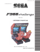
www.seuservice.com 1ST PRINTING FEB. 01 TWIN TYPE OWNER’S MANUAL SEGA ENTERPRISES, INC. USA MANUAL NO.
VISIT OUR WEBSITE!
BEFORE USING THE PRODUCT, BE SURE TO READ THE FOLLOWING: To maintain the safety: To ensure the safe usage of the product, be sure to read the following before using the product. The following instructions are intended for the users, operators and the personnel in charge of the operation of the product. After carefully reading and sufficiently understanding the warning displays and cautions, handle the product appropriately.
Specification changes (removal of equipment, conversion and addition) not designated by SEGA are not allowed. The parts of the product include warning labels for safety, covers for personal protection, etc. It is very hazardous to operate the product by removing parts and or modifying the circuits. Should doors, lids and protective parts be damaged or lost, refrain from operating the product, and contact where the product was purchased from or the office herein stated.
TABLE OF CONTENTS BEFORE USING THE PRODUCT, BE SURE TO READ THE FOLLOWING: TABLE OF CONTENTS INTRODUCTION OF THE OWNER’S MANUAL 1. HANDLING PRECAUTIONS ................................................................................................ 1 - 2 2. PRECAUTIONS CONCERNING INSTALLATION LOCATION ........................................ 3 - 4 3. OPERATION ........................................................................................................................... 5 - 6 4. NAME OF PARTS ..
SPECIFICATIONS Installation Space Height Weight Power, maximum current For TAIWAN Power, current MONITOR : 1,632 mm (W) X 1,700 mm (D) (64.3 in. X 66.9 in.) : 1,864 mm (73.3 in.) : Approx 507 kg. ( 1,117.7 lbs.) : 555 W 6.50 A (AC 110V 50 Hz AREA) 558 W 6.50 A (AC 110V 60 Hz AREA) 536 W 5.70 A (AC 120V 60 Hz AREA) 558 W 3.30 A (AC 220V 50 Hz AREA) 547 W 3.20 A (AC 220V 60 Hz AREA) 568 W 3.30 A (AC 230V 50 Hz AREA) 544 W 3.10 A (AC 230V 60 Hz AREA) 563 W 3.10 A (AC 240V 50 Hz AREA) 533 W 2.
DEFINITION OF LOCATION MAINTENANCE MAN AND SERVICEMAN Non-technical personnel who do not have technical knowledge and expertise should refrain from performing such work that this manual requires the location's maintenance man or a serviceman to carry out, or work which is not explained in this manual. Failing to comply with this instruction can cause a severe accident such as electric shock.
1. HANDLING PRECAUTIONS When installing or inspecting the machine, be very careful of the following points and pay attention to ensure that the player can enjoy the game safely. Non-compliance with the following points or inappropriate handling running counter to the cautionary matters herein stated can cause personal injury or damage to the machine. Before performing work, be sure to turn power off. Performing the work without turning power off can cause an electric shock or short circuit.
CONCERNING THE STICKER DISPLAY CONCERNING WARNING DISPLAYS SEGA product has Stickers describing the product manufacture No. (Serial No.) and Electrical Specifications. Also it has a Sticker describing where to contact for repair and for purchasing parts. When inquiring about or asking for repair, mention the Serial No. and Name of Machine indicated on the Sticker. The Serial No. indicates the product register. Identical machines could have different parts depending on the date of production.
2. PRECAUTIONS CONCERNING INSTALLATION LOCATION This product is an indoor game machine. Do not install it outside. Even indoors, avoid installing in places mentioned below so as not to cause a fire, electric shock, injury and or malfunctioning. Places subject to rain or water leakage, or places subject to high humidity in the proximity of an indoor swimming pool and or shower, etc. Places subject to direct sunlight, or places subject to high temperatures in the proximity of heating units, etc.
STOP IMPORTANT! For transporting the machine into the location's building, the minimum necessary dimensions of the opening (of doors, etc.) are 0.85m(W) and 1.55m(H). For the operation of this machine, secure a minimum area of 2.2m (W) X 2.3m (D). For ventilation, provide an approximately 20cm. space between the rear part of the cabinet and the wall. Electric current consumption MAX. 6.50 A (AC 110V 50 Hz) MAX. 6.50 A (AC 110V 60 Hz) MAX. 5.70 A (AC 120V 60 Hz) MAX. 3.30 A (AC 220V 50 Hz) MAX. 3.
3. OPERATION PRECAUTIONS TO BE HEEDED BEFORE STARTING THE OPERATION To avoid injury and trouble, be sure to constantly give careful attention to the behavior and manner of the visitors and players. In order to avoid accidents, check the following before starting the operation: Check if all of the adjusters are in contact with the surface. If they are not, the Cabinet can move and cause an accident.
PRECAUTIONS TO BE HEEDED DURING OPERATION (PAYING ATTENTION TO CUSTOMERS) To avoid injury and trouble, be sure to constantly give careful attention to the behavior and manner of the visitors and players. To avoid injury and accidents, those who fall under the following categories are not allowed to play the game. • Those who need assistance such as the use of an apparatus when walking. • Those who have high blood pressure or a heart problem.
4. NAME OF PARTS 29 TYPE MONITOR BILLBOARD CONTROL PANEL COIN CHUTE TOWER 1P SIDE COCKPIT 2P SIDE COCKPIT FIG. 4 a OVERVIEW AC COVER AC UNIT FIG. 4 b REAR VIEW TABLE 4 COCKPIT (per seat) COIN CHUTE TOWER BILLBOARD When assembled Width 820 mm 305 mm 1,609 mm 1,632 mm X Length X 1,645 mm X 515 mm X 617 mm X 1,700 mm 7 X Height X 1,520 mm X 570 mm X 354 mm X 1,864 mm Weight 228 kg 15 kg 36 kg Approx. 507 kg www.seuservice.
5. ACCESSORIES When transporting the machine, make sure that the following parts are supplied. TABLE 5 ACCESSORIES DESCRIPTION Part No. (Qty.) Note KEY MASTER 220-5576 (2) For opening/closing the doors OWNERS MANUAL 420-6507-05 (1) Figures KEY (2) For the CASHBOX DOOR If Part No. has no description, the Number has not been registered or can not be registered. Such a part may not be obtainable even if the customer desires to purchase it. Therefore, ensure that the part is in safekeeping with you.
FUSE 7A 514-5036-7000 (2) Spare, see Section 17. FLEX TUBE 310-5050-220090 (1) For communication play, refer to Section 20. CONN 22 310-5051-22 (2) For communication play, refer to Section 20. STICKER NO.OPTION 421-11210 (1) For communication play, refer to Section 20. 3 4 5 6 7 8 CARTON BOX 601-10835 (1) Used for transporting the Game Board. Refer to the following. C H K C E S ID E 9 www.seuservice.
HOW TO USE THE CARTON BOX STOP IMPORTANT! When requesting for the replacement/repair of this product's Game Board (NAOMI BOARD), follow the instructions below. Transporting the Game Board in an undesignated status is unacceptable. An erroneous handling can cause parts damage. • Put the Game Board in the Carton Box together with the Shield Case. Do not unnecessarily disassemble nor remove parts.
6. ASSEMBLING AND PRECAUTIONS Perform assembly work by following the procedure herein stated. Failing to comply with the instructions can cause electric shock hazard. Assembling should be performed as per this manual. Since this is a complex machine, erroneous assembling can cause an electric shock, machine damage and or not functioning as per specified performance. Perform connector connection securely. Insufficient insertion can cause electric shock and short circuit hazards.
Note that the master key and the cashbox door key (accessories) in addition to the tools such as a Phillips type screwdriver, wrench for M16 hexagon bolt and socket wrench are required for the assembly work. PHILLIPS TYPE SCREWDRIVER MASTER KEY 24mm WRENCH (for M16 hexagon bolt) SOCKET WRENCH Perform the tightening of hexagon bolts described in 1 above after adjusting the adjusters as per 2 . Make sure that until the adjuster adjustments are made, keep the hexagon bolts tightened temporarily.
2 Install the coin chute tower in between both cabinets. Open the coin chute door and the cashbox door to secure with the 4 hexagon bolts from inside the doors. At this time, make sure that the bolts are fastened temporarily. COIN CHUTE DOOR HEXAGON BOLT (4) M8 X 20, w/spring washer, flat washer used. COIN CHUTE TOWER FIG. 6. 1 b 3 Install the joint pipe on to the backside of both cabinets by securing with 4 hexagon bolts (at this time, temporarily).
2 SECURING IN PLACE (ADJUSTER ADJUSTMENT) Make sure that all of the adjusters are in contact with the floor. If they are not, the cabinet can move and cause an accident. Be sure to use plural workers to perform work. Depending on the specific work, there are some cases in which working by one person alone can cause personal injury and parts damage. This machine has 8 casters and 8 adjusters (Fig. 6.2a).
4 Insert the notch portions of the joint plate to the 2 adjuster bolt portions. 5 Lower the adjuster and fasten the nut upward. Secure the joint plate with the nuts and the bottom of adjuster. Secure the joint plate by fastening the nuts and the bottom of adjuster. JOINT PLATE JOINT PLATE FIG. 6. 2 c JOINT PLATE After securing the height of the adjusters, tighten all of the hexagon bolts which were fastened temporarily as per 1 above. Approx.
3 INSTALLING THE BILLBOARD The Billboard is extremely heavy, weighing approximately 36kg. When installing it, be sure to use plural workers. Performing work by one person can cause an accident. To perform work safely and securely, be sure to prepare a step which is in a secure and stable condition. Performing work without using the step can cause violent falling down accidents. 1 Mount the BILLBOARD over the TRUSS SCREW (3) black M4 X 8 cabinet. When performing work, be sure to use 3 or more workers.
3 By fastening 3 Hexagon Bolts to the inner part of the BILLBOARD inside, secure the BILLBOARD to the cabinet. 4 Secure the 2 BILLBOARD HOLDERs with 4 Hexagon Bolts for each to secure the cabinet and BILLBOARD. 5 Connect the left & right connectors. Close the BILLBOARD LID and secure with 3 Truss Screws. HEXAGON BOLT (4) black M8 X 25, w/spring washer, flat washer used HEXAGON BOLT (4 each) black M8 X 25, w/spring washer, flat washer used Connect the connector. Connect the connector.
4 INSTALLING THE AC COVERS (WIRING CONNECTION) Before starting to work, ensure that the Power SW is OFF. Failure to observe this can cause electric shock and short circuit hazards. Use care so as not to damage wirings. Damaged wiring can cause electric shock and short circuit hazards. The AC cover is used for protecting the wiring and optic fiber cables. When performing the work, be very careful so as not to cause damage by catching them. Pay due attention to handling optic fiber cables in particular.
5 POWER SUPPLY, AND EARTH CONNECTION Be sure to independently use the power supply socket outlet equipped with an Earth Leakage Breaker. Using a power supply without an Earth Leakage Breaker can cause a fire when electric leakage occurs. Ensure that the "accurately grounded indoor earth terminal" and the earth wire cable are available (except in the case where a power cord plug with earth is used). This product is equipped with the earth terminal.
2 Connect one end of the earth wire to the AC Unit earth terminal, and the other end to the indoor earth terminal. The AC Unit earth terminal has a Bolt and Nut combination. Take off the Nut, pass the earth wire through the Bolt, and fasten the Nut. Note that the Earth Wire is incorporated in the Power Cord for the Areas of AC 120V (USA) and AC 220 ~ 240V, and therefore, this procedure is not necessary. Connect the Earth Wire to the Earth Terminal. FIG. 6.
6 TURNING POWER ON Turning the AC UNIT's MAIN SW on will cause the machine to start the POWER ON check and GAME BOARD SYSTEM check automatically. In the POWER ON check, the steering wheel turns left and right, then returns to the centering position and stops. In this check, the values of V. R. inside the control panel are corrected. Until the check is finished (the steering wheel stops automatically), do not touch the steering wheel or play the game.
7 ASSEMBLING CHECK In the TEST MODE, ascertain that the assembly has been made correctly and IC BD. is satisfactory (refer to Section 9). In the test mode, perform the following test: (1) MEMORY TEST Selecting the RAM TEST on the system test mode menu screen causes the on-board memory to be tested automatically. The game board is satisfactory if the display beside each IC No. shows GOOD.
(4) SOUND TEST In the game test mode, selecting SOUND TEST causes the screen (on which sound related BD and wiring connections are tested) to be displayed. Check if the sound is satisfactorily emitted from each speaker and the sound volume is appropriate. Å° SOUND TEST Å° TITLE '-------' MUSIC STOP MUSIC FADEOUT SE-M0 No.0 SE-M1 No.0 SE-M2 No.0 SE-S0 No.0 -> EXIT SELECT WITH SERVICE BUTTON AND PRESS TEST BUTTON (5) C.R.T. TEST C.R.T.
7. PRECAUTIONS TO BE HEEDED WHEN MOVING THE MACHINE When moving the machine, be sure to unplug the power plug. Moving the machine with the plug as is inserted can damage the power cord, and cause fire and electric shock hazards. When moving the machine on the floor, retract the Adjusters and ensure that Casters make contact with the floor. During transportation, pay careful attention so that Casters do not tread power cords and earth wires.
Do not push an independent (detached) cockpit from the left/right direction. FIG. 7 b Have casters make contact with the floor. FIG. 7 c 25 www.seuservice.
8. CONTENTS OF GAME The following explanations apply to the case the product is functioning satisfactorily. Should there be any moves different from the following contents, some sort of faults may have occurred. Immediately look into the cause of the fault and eliminate the cause thereof to ensure satisfactory operation. PADDLE SHIFT STEERING WHEEL START BUTTON ASSIST FUNCTION BUTTONS BRAKE PEDAL ACCEL. PEDAL From GAME START up to the end of SELECT Insert a credit worth number of coins.
• In case of single play > Select Game Contents 1) Select the course from among the 6 courses in the Course Select screen. Turn the Steering Wheel left and right to choose and decide the selection by stepping on the Accelerator Pedal. 2) Select the level from the 2 levels in the Level Select screen. 27 www.seuservice.
The following levels are available in single play. NOVICE INTERMEDIATE About Assist Functions • Automatic • All Assist functions are offered. • Semi-Automatic (Paddle-shift) • All Assist functions except IBS are offered. SC Stability Control Stabilizes and controls position of the car in a cornering. TC Traction Control Controls the powertrain in a wheelspin, and stabilizes the control of the car. ABS Anti-lock Brake System Prevents your tires from locking when you brake.
3) Select the mode from among the 3 modes in the Mode Select screen. The following game modes are available in single play. TRAINING MODE: The course is navigated by the screen displays & voices and suitable for beginners to learn how to drive, the characteristics of the car, and to remember the course. In this mode, finishing the predetermined laps within the time limit to goal results in a game over.
< In case of communication play > Press START button during the entry acceptance to enter the Communication Play mode. Select Game Contents 1) Select the course from among the 6 courses in the Course Select screen. www.seuservice.
During the Communication Play, the following communication conditions are available. Setting of the communication conditions can be changed in the GAME TEST mode. HEAT : An exciting, nip-and tuck race from the game start to the end. AID : By taking advantage of the Assist Functions, the NOVICE (AT) player can run the advanced player close. PRO : Offers a hotly contested game under the equal condition among all cars. 2) Select the level from among 3 levels in the Level Select screen.
< In case of AID or PRO > In case of AID NOVICE • Automatic • All Assist functions are offered. INTERMEDIATE • Semi-Automatic (Paddle-shift) • All Assist functions except IBS are offered. • In this mode, Handicap is not given. In case of PRO NOVICE • Automatic • All Assist functions are offered. • In this mode, Handicap is not given. INTERMEDIATE • Semi-Automatic (Paddle-shift) • All Assist functions except IBS are offered. • In this mode, Handicap is not given. www.seuservice.
9. EXPLANATION OF TEST AND DATA DISPLAY By operating the switch unit, periodically perform the tests and data check. When installing the machine initially or collecting cash, or when the machine does not function correctly, perform checking in accordance with the explanations given in this section. The following shows tests and modes that should be utilized as applicable. NAOMI GAME BOARD is used for the product.
9 - 1 SWITCH UNIT AND COIN METER Never touch places other than those specified. Touching places not specified can cause electric shock and short circuit accidents. STOP IMPORTANT! Adjust to the optimum sound volume by considering the environmental requirements of the installation location. If the COIN METER and the game board are electrically disconnected, game play is not possible.
9 - 2 SYSTEM TEST MODE STOP IMPORTANT! The contents of setting changes in SYSTEM ASSIGNMENTS, COIN ASSIGNMENTS, and GAME TEST MODE are stored when the test mode is EXITed. If the power is turned off before EXITing, the contents of setting changes are ineffective. Be very careful of this point. This test mode mainly allows the IC Board to be checked for accurate functioning, monitor color to be adjusted as well as COIN ASSIGNMENTS and GAME ASSIGNMENTS to be adjusted.
1 RAM TEST This allows for checking the functioning of the RAM on the NAOMI Main BD. "GOOD" is displayed for satisfactory RAMs, and "BAD" is indicated for irregular RAMs, if any. RAM TEST IC29 IC35 IC16 IC20 IC09 IC11 GOOD GOOD GOOD GOOD GOOD GOOD IC18 IC22 IC10 IC12 GOOD GOOD GOOD GOOD PRESS TEST BUTTON TO EXIT During test, "TESTING NOW" is displayed. Press the TEST button to return to the menu mode. www.seuservice.
2 JVS TEST In this test, Specifications of the I/O Board connected to NAOMI can be checked, and INPUT TEST can be performed. First, I/O Board Specifications are displayed. JVS TEST INPUT TEST (A) NEXT NODE (B) -> EXIT (C) NODE 1/1 NAME SEGA ENTERPRISES,LTD. 837-13741 I/O CONTROL BD Ver0.15 99/06 CMD VER 1.1 JVS VER 2.0 COM VER 1.
3 SOUND TEST Sound Output test can be performed. Beep sounds can be emitted from each of left/right Speakers. SOUND TEST fEmitted from the right-hand side Speaker. fEmitted from the left-hand side Speaker. fReturns to the menu mode. RIGHT SPEAKER OFF LEFT SPEAKER OFF -> EXIT SELECT WITH SERVICE BUTTON AND PRESS TEST BUTTON 4 C.R.T. TEST A) RGB COLOR ADJUSTMENT SCREEN In this page, monitor color can be checked. C.R.T.
5 SYSTEM ASSIGNMENTS STOP IMPORTANT! If the settings of CABINET TYPE and MONITOR TYPE are not suitable for the connected game, Error Message is displayed after turning power on and upon finishing the TEST mode, and in this case, game is not playable. The setting of cabinet and board can be changed. Game related assignments such as game difficulty, etc. are performed in 2-3 GAME TEST MODE. 1) 2) 3) Press the SERVICE button to move the arrow. Bring the arrow to the desired item.
6 COIN ASSIGNMENTS In this mode, the setting of incremental credit increase as against coin insertion can be changed. 1) 2) 3) Press the SERVICE button to move the arrow. Bring the arrow to the desired item. Press the TEST button to change the setting. Upon finishing the setting, bring the arrow to EXIT and press the TEST button.
(C) MANUAL SETTING The Credit's incremental increase settings as against a coin insertion are shown in further details than in (B) above (refer to Table 3). Also, note that when this MANUAL SETTING is performed, (B) COIN CREDIT setting becomes ineffective.
Table 1: COIN/CREDIT SETTING (COIN CHUTE COMMON TYPE) 1 1 1 1 1 1 1 1 1 1 1 2 1 1 1 2 1 COIN CHUTE 1 COIN 1 CREDIT COIN 2 CREDITS COIN 3 CREDITS COIN 4 CREDITS COIN 5 CREDITS COIN 2 CREDITS COIN 5 CREDITS COIN 3 CREDITS COIN 4 CREDITS COIN 5 CREDITS COIN 6 CREDITS COINS 1 CREDIT COIN 1 CREDIT COIN 2 CREDITS COIN 1 CREDIT COINS 3 CREDITS COIN 3 CREDITS SETTING #20 3 4 1 2 3 4 1 COINS COINS COIN COINS COINS COINS COIN SETTING #21 SETTING #22 5 COINS 1 COIN 1 CREDIT 2 CREDITS SETTING #23 2 4 5 1 COI
Table 2: MANUAL SETTING C O I N TO C R E D I T 1 COIN 2 COIN 3 COIN 4 COIN 5 COIN 6 COIN 7 COIN 8 COIN 9 COIN BONUS ADDER NO BONUS ADDER COIN CHUTE (#1/ #2) MULTIPLIE R 43 1 CREDIT 1 CREDIT 1 CREDIT 1 CREDIT 1 CREDIT 1 CREDIT 1 CREDIT 1 CREDIT 1 CREDIT 2 3 4 5 6 7 8 9 COINS GIVE COINS GIVE COINS GIVE COINS GIVE COINS GIVE COINS GIVE COINS GIVE COINS GIVE 1 1 1 1 1 1 1 1 EXTRA COIN EXTRA COIN EXTRA COIN EXTRA COIN EXTRA COIN EXTRA COIN EXTRA COIN EXTRA COIN 1 1 1 1 1 1 1 1 1 COINS COUNTS AS COI
(G) SEQUENCE SETTING Number of credits required for starting game, etc. can be set. Each sequence can be set between 1Å`5 credit(s).
7 BOOKKEEPING • BOOKKEEPING 1/2 This allows such data as operating time/No. of coins inserted/ No. of credits to be checked. Perform work by watching the front monitor only. BOOKKEEPING 1/2 TOTAL TIME 0D 00H 00M 00S CREDIT COIN COIN COIN COIN 1 2 3 4 0 0 0 0 0 TOTAL COIN 0 COIN CREDIT 0 SERVICE CREDIT 0 TOTAL CREDIT 0 PRESS TEST BUTTON TO CONTINUE Press the TEST button to proceed to BOOKKEEPING 2/2. • BOOKKEEPING 2/2 Each sequence displays the frequency of functioning.
8 BACKUP DATA CLEAR Clears the contents of BOOKKEEPING (SYSTEM TEST MODE). The data regarding the coins, the credits, and the total time in the BOOKKEEPING in the GAME TEST Mode are also cleared. BACKUP DATA CLEAR YES(CLEAR) -> NO(CANCEL) SELECT WITH SERVICE BUTTON AND PRESS TEST BUTTON When clearing, bring the arrow to YES by using the SERVICE button and press the TEST button. Bring the arrow to NO and press the TEST button to have the menu mode return without clearing the data.
10 ROM BOARD TEST In this test, on-ROM-BD ROM check is executed. If GOOD is displayed, it is satisfactory. However, Program ROMs (IC22) do not display GOOD or BAD. BYTE and WORD refers to the check sum of each unit. ROM BOARD TEST [XXXXX XXXXX XXXXX] NO.
9 - 3 GAME TEST MODE Press TEST Button to display the SYSTEM TEST MODE MENU. SYSTEM MENU XXXXX VERSION RAM TEST JVS TEST SOUND TEST C.R.T. TEST SYSTEM ASSIGNMENTS COIN ASSIGNMENTS BOOKKEEPING BACKUP DATA CLEAR CLOCK SETTING ROM BOARD TEST GAME TEST MODE [F355 CHALLENGE XXXXX] -> EXIT SELECT WITH SERVICE BUTTON AND PRESS TEST BUTTON • By pressing SERVICE Button, move the arrow (->) to select the GAME TEST MODE. Press TEST Button to enter GAME TEST MODE. • The screen displays the GAME TEST MODE MENU.
A) INPUT TEST Selecting INPUT TEST displays the following screen on the monitor. INPUT TEST - SYSTEM SWITCH CHUTE #1 OFF CHUTE #2 OFF TEST OFF B TEST OFF SERVICE OFF B SERVICE OFF - GAME SWITCH START OFF SC OFF TC OFF ABS OFF IBS OFF - WING SHIFT WING L ON WING R OFF - ANALOG DEVICE HANDLE 7B H ACCEL 2E H BRAKE 2F H - OTHER DEVICE VISUAL MEMORY UNCONNECTED PRESS SERVICE + TEST BUTTON TO EXIT This test checks the satisfactory operation of each input device (SW or VR).
B) OUTPUT TEST This test displays the following screen on the monitor. OUTPUT TEST MENU LAMP TEST DRIVE BOARD TEST -> EXIT TO SYSTEM TEST MODE SELECT WITH SERVICE BUTTON AND PRESS TEST BUTTON • The OUTPUT TEST displays the following screen on the monitor. a) LAMP TEST b) DRIVE BOARD TEST a) LAMP TEST Selecting LAMP TEST displays the following screen on the monitor.
b) DRIVE BOARD TEST Selecting DRIVE BOARD TEST causes the following to be displayed. DRIVE BOARD TEST STOP MOTOR ROLL RIGHT ROLL LEFT SET CENTER OF STEER 7bH(80H) -> EXIT SELECT WITH SERVICE BUTTON AND PRESS TEST BUTTON In ROLL RIGHT and ROLL LEFT, check to see if the motor turns the Steering Wheel clockwise and counterclockwise. After having confirmed satisfactory motor operation, stop the motor by selecting STOP MOTOR. Set the center values of the Steering Wheel in the SET CENTER OF STEER.
D) GAME ASSIGNMENTS When GAME ASSIGNMENTS is selected, the following menu screen appears on the monitor. GAME ASSIGNMENTS LINK ID SINGLE CABINET TWIN CAR NUMBER 1 DIFFICULTY NORMAL GAME MODE NORMAL(SPRINT) HANDICAP HEAT CONTINUE ANY NUMBER OF TIMES MOTOR POWER 80% VISUAL MEMORY OFF LOCATION NAME ENTRY -> EXIT SELECT WITH SERVICE BUTTON AND PRESS TEST BUTTON LINK ID : Communication play setting. Set to either SINGLE, MASTER, or SLAVE. When operating the machines independently, set to SINGLE.
E) BOOKKEEPING Selecting BOOKKEEPING causes the following to be displayed on the monitor. BOOKKEEPING PAGE 1/2 COIN/CREDIT & TIME DATA 1999 YEAR 9 MONTH 19 DAY 16:27 41 CHUTE #1 XXX CHUTE #2 XXX TOTAL COIN XXX COIN CREDIT XXX SERVICE CREDIT XX TOTAL CREDIT XXX TOTAL PLAY GAMES XXX TOTAL CONTINUE GAMES X CONTINUE RATIO X.XX TOTAL TIME XD XXH XXM XXS PLAY TIME XD XXH XXM XXS AVERAGE TIME XD XXH XXM XXS PRESS TEST BUTTON TO NEXT PAGE CHUTE #X: Total number of coins put in.
Press TEST Button to display the play time list in each course on the monitor.
10. CONTROL PANEL (HANDLE MECHA) Before starting to work, ensure that the Power SW is OFF. Failure to observe this can cause electric shock or short circuit. Use care so as not to damage wirings. Damaged wiring can cause electric shock or short circuit. Do not touch undesignated places. Touching places not designated can cause electric shock or short circuit. This work should be performed by the Location's Maintenance Man or Serviceman.
10 - 2 ADJUSTING AND REPLACING THE HANDLE's (STEERING WHEEL's) V.R. STOP After the replacement or adjustment of Volume (V. R.), be sure to set the centering value of Steering Wheel's V.R. in the Test Mode. IMPORTANT! ADJUSTlNG THE VOLUME 1 Loosen the 2 screws which secure the Volume Bracket to disengage gear mesh. 2 With the Steering Wheel in the centering position, cause gears to be engaged in the manner so that the Volume Shaft is in the status shown as per FIG. l0.2.
10 - 3 GREASING STOP IMPORTANT! Be sure to use the designated grease. Using undesignated grease can cause parts damage. Do not apply greasing to undesignated places. Failure to observe this can cause malfunctioning or quality deterioration of parts. Apply greasing to gear mesh portions once every 3 months. Use GREASE MATE (SEGA PART NO. 090-0066). VOLUME GEAR MESH PORTION FIG. 10. 3 57 www.seuservice.
11. ACCELERATOR & BRAKE Before starting to work, ensure that the Power SW is OFF. Failure to observe this can cause electric shock or short circuit. Use care so as not to damage wirings. Damaged wiring can cause electric shock or short circuit. Do not touch undesignated places. Touching places not designated can cause electric shock or short circuit. This work should be performed by the Location's Maintenance Man or Serviceman.
2 Loosen the screw which secure the Potentiobase, and adjust the Volume value by moving the Base. (FIG. 11. 1 b) 3 Secure the Potentiobase. SCREW M5 X 12, w/flat & spring washers 4 Perform volume setting in the volume setting mode. POTENTIOBASE V.R. 220-5484 220-5373 FIG. 11. 1 b TRUSS SCREW(2) M4 X 8 REPLACING THE VOLUME 1 Turn the power off. POTENTIOCOVER 2 Take out the 2 screws and remove the Potentiocover (FIG. 11. 1 c). 3 Disconnect the connector of the volume to be replaced.
12. PADDLE (WING) SHIFT Before starting to work, ensure that the Power SW is OFF. Failure to observe this can cause electric shock or short circuit. Use care so as not to damage wirings. Damaged wiring can cause electric shock or short circuit. Do not touch undesignated places. Touching places not designated can cause electric shock or short circuit. This work should be performed by the Location's Maintenance Man or Serviceman.
4 Take out 2 screws to replace the SCREW (2) M3 X 16 Microswitch. 5 Adjust Microswitch's actuator to an angular position so as not to touch the Switch when operating the Shift Lever. 6 Fasten 2 screws to secure the Microswitch. 7 Check to ensure that the Switch goes ON and OFF in consistency with the operation. MICROSWITCH 509 - 5387 PHOTO 12 b 61 www.seuservice.
www.seuservice.
63 www.seuservice.
www.seuservice.com 64 Tom Happ Ph: 847-593-6161 ext. 107 tom.happ@happcontrols.com Fx: 847-956-2091 Happ Controls, 106 Garlisch Drive, Elk Grove, IL 60007 Visit our website http://www.happcontrols.
OPTIONAL DOLLAR BILL ACCEPTOR THE COIN DOOR ASSEMBLY USED ON F355 challenge TWIN TYPE COMES EQUIPPED TO ACCEPT A DOLLAR BILL ACCEPTOR. ALL NEEDED WIRING CONNECTIONS ARE CONVIENENTLY LOCATED INSIDE THE GAME FOR THIS APPLICATION. THE COIN DOOR CAN ACCCOMMODATE THE FOLLOWING VALIDATOR(S): FORWARD-MOST HOLE POSITION **42-1155-00 Mars 2000 series MARS VALIDATOR $1, 2, 5 300 CAP The frame and cashbox enclosure on this coindoor has been modified to accomodate a Mars 2000 series upstacker.
14. MONITOR 14 - 1 CAUTIONS AND WARNINGS CONCERNING THE SAFETY FOR HANDLING THE MONITORS Before handling the monitors, be sure to read the following explanations and comply with the caution/warning instructions given below. Note that the caution/warning symbol marks and letters are used in the instructions. Indicates that handling the monitors erroneously by disregarding this warning may cause a potentially hazardous situation, which could result in death or serious injury.
Static Electricity Touching the CRT surface sometimes causes you to slightly feel electricity. This is because the CRT surfaces are subject to static and will not adversely affect the human body. Installation and removal Ensure that the Magnetizer Coil, FBT (Fly-Back Transformer), Anode Lead and Focus Lead are not positioned close to the sheet metal work's sharp edges, etc. and avoid damaging the insulated portions so as not to cause electric shock and malfunctioning.
For the purpose of static prevention, special coating is applied to the CRT face of this product. To protect the coating, pay attention to the following points. Damaging the coating film can cause electric shock to the customers. Do not apply or rub with a hard item (a rod with pointed edge, pen, etc.) to or on the CRT surfaces. Avoid applying stickers, seals, etc. on the CRT face. Aluminum Foil Do not remove aluminum foils from the CRT corners.
14 - 3 ADJUSTMENT METHOD Monitor adjustments have been made at the time of shipment. Therefore, do not make further adjustment without a justifiable reason. Adjusting the monitor which contains high tension parts is a dangerous work. Also, an erroneous adjustment can cause deviated synchronization and image fault, resulting in malfunctioning. When making adjustment, utilize a resinous Alignment Rod. Servicing with bare hand or using conductive tools can cause electric shock.
○ 1 R-GAIN ...... (24K mode) ○ NANAO monitor: ○ ○ 2 G-GAIN .......... Controls colors. ○ 3 B-GAIN ...... \ 4 BRIGHT .......... Controls screen brightness. 5 H. SIZE ........... Controls horizontal screen size. 7 H. POSI ........... Controls horizontal display position on screen. 8 V. SIZE ........... Controls vertical screen size. 10 V. POSI ........... Controls vertical display position on screen. 11 CONTRAST .... Adjusts image contrast. www.seuservice.
15. REPLACING THE FLUORESCENT LAMP When performing work, be sure to turn power off. Working with power on can cause electric shock and short circuit hazards. The Fluorescent Lamp, when it gets hot, can cause burn. Be very careful when replacing the Fluorescent Lamp. Be sure to use lamps of the designated rating. Using lamps of undesignated rating can cause a fire or malfunctioning. To perform work safely and securely, be sure to prepare a step which is in a secure and stable condition.
CATHODE TUBE TRUSS SCREW (6) black M4 X 8 1 Take off the 6 truss screws to remove the UPPER LID. UPPER LID 2 Take off the 2 flange nuts and 2 screws to remove the HOLDER PLATE B. The same can be applied to the HOLDER PLATE A. 3 Remove the HOLDER PLATE, and the CATHODE TUBE appears. Disconnect the connector to remove the CATHODE TUBE. FIG. 15 c SCREW (2) M4 X 8, w/flat & spring washers FLANGE NUT (2) M4 HOLDER PLATE B Disconnect the connector CATHODE TUBE 390-5697-01 FIG. 15 d HOLDER PLATE A www.
16. PERIODIC INSPECTION TABLE The items listed below require periodic check and maintenance to retain the performance of this machine and to ensure safe business operation. Be sure to check once a year to see if Power Cords are damaged, the plug is securely inserted, dust is accumulated between the Socket Outlet and the Power Plug, etc. Using the product with dust as is accumulated can cause fire and electric shock hazards.
SEAT (Greasing to Seat Rail Portion) Move the Seat to the rearmost portion and apply spray greasing to the portion shown at the right once every 3 months by using NOK KLUBER L60 or GREASE MATE SEGA PART No. 090-0066. After greasing, move the Seat a few times forward and backward so as to allow the grease to be applied all over uniformly. Be sure to wipe grease which attaches to the surfaces of the PROTECT RUBBER on the Seat Rail, or any excess grease. FIG.
17. TROUBLESHOOTING In order to prevent electric shock and short circuit, be sure to turn power off before performing work. Be careful so as not to damage wirings. Damaged wiring can cause electric shock or short circuit. After removing the cause of the functioning of the Circuit Protector, reinstate the Circuit Protector. Depending on the cause of the functioning, using the Circuit Protector as is without removing the cause can cause generation of heat and fire hazard.
TABLE 17 b PROBLEMS Steering Wheel reaction strength is incorrect. Deviation of Center. CAUSE COUNTERMEASURES Power ON check not performed correctly. Turn off power and then turn it back on again. Complete the power on check. V.R. position deviated. Adjust V. R. value in the test mode (see Sec. 9). V.R. malfunctioning. Replace V.R. (see Sec. 10). Steering Wheel reaction strength is insufficient. Reaction Mecha's secular change. Adjust V. R. value in the Test mode (see Sec. 9).
REPLACMENT OF FUSE Fuse replacements other than those specified can cause accidents and are strictly forbidden. In case fuse replacements other than those stated in this manual are necessary, contact where you purchased the product from for inquiries regarding this matter. In order to prevent an electric shock, be sure to turn power off and unplug from the socket outlet before performing work by touching the internal parts of the product. Be careful so as not to damage wirings.
18. GAME BOARD In order to prevent electric shock and short circuit hazards, be sure to turn power off before performing work. Be careful so as not to damage wirings. Damaged wiring can cause fire, electric shock and short circuit hazards. Do not expose the Game BD, etc. without a good reason. Failure to observe this can cause electric shock hazard or malfunctioning. In this product, setting changes are made during the test mode. The Game BD need not be operated. Use the Game BD, etc.
NOT USED 3 Unlock and take off the 2 truss screws from the side of the base as shown. 4 Turn the knob to unlock. The seat can be inclined in the direction shown. When inclining the seat, be careful so as not to damage the seat parts. Carefully cause the backrest portion of the seat to come into contact with the floor. If the floor has hard surfaces, protect the seat from damage by using a cloth, etc. on the floor surfaces.
18 - 2 FILTER BOARD STOP IMPORTANT! Ensure that the DIP SW setting is performed as designated. Failure to observe this may cause functioning not suitable for the actual operation, or malfunctioning. DIP SW see FIG.18.2 b RGB1 (NOT USED) FILTER BOARD SHIELD CASE Connect RGB CABLE to RGB2. FIG. 18. 2 a DIP SW SETTING Set all DIP SW on the FILTER BOARD to OFF. FIG. 18. 2 b www.seuservice.
18 - 3 ERROR DISPLAY (DRIVE CONTROL BOARD) Be careful so as not to damage wirings. Damaged wiring can cause electric shock and short circuit hazards. Do not touch undesignated places. Touching places not specified can cause electric shock and short circuit hazards. If an irregularity occurs in the Drive Control Board, etc., the ERROR message is shown on the screen and the 7-SEG display on the Drive Control BD. Take countermeasures in the manner corresponding to the ERROR message.
If Error display is shown on the screen, remove BASE LID F without turning power off to check the 7-SEG display on the Drive Control Board. At this time, if the power is turned off, each of Er 23, 24 and 25 which could have occurred during operation may not be displayed. Perform the DIP SW setting on the DRIVE CONTROL BOARD and the ASSY MAIN BD BASE as shown below. DRIVE CONTROL BOARD w/7-SEG DISPLAY DIP SW setting as shown.
19. DESIGN RELATED PARTS OPPOSITE SIDE OPPOSITE SIDE For the Warning Display stickers, refer to Section 1. 83 www.seuservice.
No. PART No.
20. COMMUNICATION PLAY For this game, 4 machines can be connected to allow up to 8 players to play simultaneously. 20 - 1 INSTALLATION PRECAUTIONS 1) When linking a number of machines, be sure to supply sufficient power for the corresponding number of machines. The per unit standard voltage/amperage is 100 X 120V/ 10A and 220 X 240V/5A. APPROXIMATELY 0.2m 2) Due to the length of the communications cable, the distance in between the machines will be approximately 0.2 meters or less.
3 Attach CONNECTOR 22 to the both ends of FLEX TUBE, and assemble the PROTECT TUBE. First, disassemble CONNECTOR 22 (Fig. 20. 2 b). 4 First pass the plastic nut through the flex tube. Otherwise, the following work can not be performed and therefore, be very careful of this point. 5 Install the holder and then the "insert" to the end of the flex tube by turning them as in bolts and nuts (Fig. 20. 2 c). 6 Tighten the plastic nut to the connector.
8 Connect the communication cable. Redo the connection which is currently made for TWIN (for 2P LINK). Depending on the number of units to be connected, communication connections are different. Make connection correctly as shown below. The communication cable is optic-fiber made and will break if excessively bent. Handle with care. STOP IMPORTANT! BLACK (TX) RED (RX) TX RX FIG. 20.
6 P LINK RX TX RX TX CAR NUMBER 1 RX TX RX RX TX TX RX RX TX CAR NUMBER 2 CAR NUMBER 3 TX RX RX TX TX RX TX CAR NUMBER 4 CAR NUMBER 5 RX TX RX TX CAR NUMBER 6 8P LINK RX TX RX TX CAR NUMBER 1 RX TX RX TX CAR NUMBER 2 RX TX RX TX CAR NUMBER 3 RX TX RX RX TX TX RX TX CAR NUMBER 4 CAR NUMBER 5 RX TX RX TX CAR NUMBER 6 RX TX RX RX TX CAR NUMBER 7 TX RX TX CAR NUMBER 8 FIG. 20. 2 h 9 Apply Seat No. Stickers in the manner corresponding to applicable seats.
20 - 3 SETTING FOR COMMUNICATION PLAY During interactive play, if communication is interrupted due to some cause, the Network Check screen appears after finishing the game. STOP IMPORTANT! Cause all of the seats to enter the Test Mode and change the GAME ASSIGNMENTS of each seat for communication play. For the changing procedure, refer to the explanations of Section 9. 1 Press TEST button to enter the test mode and proceed to GAME TEST mode. Choose GAME ASSIGNMENTS in the GAME TEST mode.
21. PARTS LIST (D-1/3) Details of PART A Details of PART B 1 TOP ASSY FRI TWIN www.seuservice.
1 TOP ASSY FRI TWIN ITEM NO. (D-2/3) PART NO.
1 TOP ASSY FRI TWIN 401 402 403 404 405 407 408 409 410 411 412 414 415 416 417 418 / / / PART NO.
2 ASSY BILLBOARD (FRI-0200) (D-1/2) 93 www.seuservice.
2 ASSY BILLBOARD (FRI-0200) ITEM NO. (D-2/2) PART NO.
3 ASSY LIGHT (FRI-0220) ITEM NO. PART NO. DESCRIPTION FRI-0221 FRI-0222 FRI-0223 HOLDER HOLDER PLATE A HOLDER PLATE B 101 102 103 104 390-5697-01 838-13038 280-5275-SR10 601-0460 CATHODE TUBE PINK W/CONN CATHODE TUBE INVERTER 12V CORD CLAMP SR10 PLASTIC TIE BELT 100 MM 201 202 203 050-F00400 050-U00300 060-F00300 FLG NUT M4 U NUT M3 FLT WSHR M3 1 2 3 95 NOTE www.seuservice.
4 ASSY COINCHUTE TOWER (FRI-0300) www.seuservice.
4 ASSY COINCHUTE TOWER (FRI-0300) ITEM NO. PART NO. DESCRIPTION 1 2 3 4 5 6 7 8 9 10 11 12 13 FRI-0350 SPG-0301 DRT-0301 DP-1167 253-5366 421-6591-01 421-7501-02 DYN-0303X DYN-0305 105-5202 SPG-0302 SPG-0303 440-WS0002XEG SW UNIT COIN CHUTE TOWER COIN METER BRKT TNG LKG CASH BOX STICKER COIN METER STICKER 6.3V 0.
5 SW UNIT (FRI-0350) ITEM NO. PART NO. DESCRIPTION 1 2 SPG-0351 421-11170 SW BRKT STICKER SW UNIT FRI 101 102 103 104 105 509-5028 220-5179 601-0042 601-0460 310-5029-F20 SW PB 1M VOL CONT B-5K OHM KNOB 22 MM PLASTIC TIE BELT 100 MM SUMITUBE F F 20MM 301 302 303 304 305 306 600-6373-53 600-7076-055 600-6373-67 600-7076-065 600-6873-064 600-6873-065 WIRE HARN TEST & SERVICE LEFT WIRE HARN VOL LEFT YE WIRE HARN TEST & SERVICE RIGHT WIRE HARN VOL RIGHT BL WIRE HARN S.VOLUME 1P WIRE HARN S.
6 AC UNIT MAIN (FRI-0400) (D-1/2) 99 www.seuservice.
6 AC UNIT MAIN (FRI-0400) ITEM NO. (D-2/2) PART NO. DESCRIPTION APC-1531 DYN-0402 421-8202 421-7515 421-7468-01 AC BRKT NOISE FILTER BASE STICKER EARTH MARK STICKER FIBER CABLE TX/RX STICKER C.P W/PIC 104 105 106 107 108 109 110 214-0202 512-5046-15000 512-5046-8000 450-5126 450-5134 450-5133 509-5453-91-V-B 270-5115 280-0417 211-5479-01 310-5029-K20 280-5009-01 601-0460 AC INLET PANEL TYPE C.P 15000MA CE UL C.
7 AC UNIT SUB (FRI-0700) ITEM NO. PART NO. DESCRIPTION 1 2 APC-1531 421-7515 AC BRKT STICKER FIBER CABLE TX/RX 101 211-5479-01 CONN OPT JOINT 201 000-P00312-W M SCR PH W/FS M3 X 12 301 302 FRI-61026 FRI-61037 WIRE HARN EXT AC UNIT WIRE HARN EXT AC UNIT SUB 101 NOTE www.seuservice.
(D-1/2) (For ADJUSTMENT) Details of PART A 8 ASSY COCKPIT 1P (FRI-10001) www.seuservice.
8 ASSY COCKPIT 1P (FRI-10001) ITEM NO. (D-2/2) PART NO.
(D-1/2) (For ADJUSTMENT) Details of PART A 9 ASSY COCKPIT 2P (FRI-11001) www.seuservice.
9 ASSY COCKPIT 2P (FRI-11001) ITEM NO. (D-2/2) PART NO.
FAN 10 ASSY CONTROL PANEL TWIN EXP (FRI-12001-01) www.seuservice.
10 ASSY CONTROL PANEL TWIN EXP (FRI-12001-01) ITEM NO. PART NO.
10 ASSY CONTROL PANEL TWIN EXP (FRI-12001-01) ITEM NO. 301 302 303 304 305 306 307 310 PART NO. DESCRIPTION 600-6873-043 600-6873-047 600-6873-050 600-6972-0130 600-7064-027 600-7064-028 FRI-61062 600-6972-0200 WIRE HARN VIEW BUTTON WIRE HARN CONT PNL FAN WIRE HARN EXT VOLUME C WIRE HARN EARTH ID5 0130MM WIRE HARN EXT ENCODER B WIRE HARN EXT MOTOR B WIRE HARN VMS WIRE HARN EARTH ID5 0200MM www.seuservice.
11 VM UNIT FRI (FRI-1250) ITEM NO. PART NO. DESCRIPTION 1 2 NOA-1901 839-1132 VM GUIDE MAPLE/LM CONVERT BD W/VM SKT 201 012-P00306 TAP SCR #2 PH 3 X 6 109 NOTE www.seuservice.
12 ASSY EFECT SW TWIN (FRI-1290) ITEM NO. PART NO. DESCRIPTION 1 2 3 4 5 6 DYN-1291 171-6478B FRI-1291 FRI-1292 FRI-1293 FRI-1294 VR BUTTON BRKT PC BD LIGHTING SWX5 BUTTON SHEET SC FRI TWIN BUTTON SHEET TC FRI TWIN BUTTON SHEET ABS FRI TWIN BUTTON SHEET IBS FRI TWIN 212-5205-12 509-5560-Y 509-5485 253-5383-02 253-5383-04 CONN JST M 12P RTA PB SW W/L 6V 1L Y PB W/L 6V W/O LEN,PLT 5L BUTTON COVER 5L GR BUTTON COVER 5L BL 101 102 103 104 105 www.seuservice.
(D-1/2) GREASING 13 ASSY HANDLE MECHA (FRI-2550) 111 www.seuservice.
13 ASSY HANDLE MECHA (FRI-2550) (D-2/2) ITEM NO. PART NO.
113 Details of PART B (D-1/2) ACTUATOR 14 ASSY PADDLE SHIFT TWIN (FRI-2600) www.seuservice.
14 ASSY PADDLE SHIFT TWIN (FRI-2600) ITEM NO. PART NO.
15 ASSY BASE BOX (FRI-1500) ITEM NO. PART NO. DESCRIPTION FRI-1501 DYN-2003 DYN-2004 DYN-2005X DYN-2006 FRI-1510 DYN-2007X DYN-2009X MAIN BASE BASE LID F LOCK TNG FLOOR MAT HINGE 480 ASSY BASE LID R LID EDGE L LID EDGE R 101 220-5575 CAM LOCK MASTER W/O KEY 201 202 203 204 205 000-T00512-0B 031-000414-0C 031-000514-0B 050-F00400 050-F00500 M SCR TH BLK M5 X 12 CRG BLT CRM M4 X 14 CRG BLT BLK M5 X 14 FLG NUT M4 FLG NUT M5 1 2 3 4 5 6 7 8 115 NOTE www.seuservice.
16 ASSY BASE LID R (FRI-1510) ITEM NO. PART NO. DESCRIPTION 1 2 3 4 5 DYN-2011 DYN-2012 DYN-2013 DYN-2014 FRI-1511 LOCK ROD A LOCK ROD B LOCK ARM ROD HOLDER BASE LID R 101 102 103 601-7551 601-5526-170 280-5008 LOCK HANDLE BUSH 1.6T (L=170) CORD CLAMP 15 201 202 203 045-C02520 031-000510-0B 050-F00500 COT PIN 2.5 X 20 CRG BLT BLK M5 X 10 FLG NUT M5 www.seuservice.
(D-1/2) BOLT (white) BOLT (yellow) 17 ASSY SEAT TWIN 1P (FRI-1600) 117 www.seuservice.
17 ASSY SEAT TWIN 1P (FRI-1600) ITEM NO. (D-2/2) PART NO.
(D-1/2) BOLT (white) BOLT (yellow) 18 ASSY SEAT TWIN 2P (FRI-1700) 119 www.seuservice.
18 ASSY SEAT TWIN 2P (FRI-1700) ITEM NO. (D-2/2) PART NO.
19 ASSY WOOFER (STC-1650) ITEM NO. PART NO. DESCRIPTION 1 2 STC-1651 STC-1652 WOOFER BRKT F WOOFER BRKT R 101 130-5160 SUB WOOFER 4OHM 30W 201 202 012-P00412 060-F00400 TAP SCR #2 PH 4 X 12 FLT WSHR M4 121 NOTE www.seuservice.
(D-1/2) FAN FAN 20 ASSY MAIN BASE 1P (FRI-20001) www.seuservice.
20 ASSY MAIN BASE 1P (FRI-20001) (D-2/2) ITEM NO. PART NO.
(D-1/2) FAN FAN 20 ASSY MAIN BASE 2P (FRI-21001) www.seuservice.
21 ASSY MAIN BASE 2P (FRI-21001) (D-2/2) ITEM NO. PART NO.
22 ASSY ACCEL & BRAKE (FRI-2250) www.seuservice.
22 ASSY ACCEL & BRAKE (FRI-2250) (D-2/2) ITEM NO. PART NO.
23 ABSORBER UNIT TWIN (FRI-2350) ITEM NO. PART NO. DESCRIPTION 1 2 3 4 5 FRI-2351 FRI-2352 FRI-2303 FRI-2305 FRI-2306 ABSORBER BRKT TWIN ABSORBER SUB BRKT TWIN PLUNGER COMP SPRING FRI STOPPER SHAFT 101 601-10662 SHOCK ABSORBER W/O CAP 201 202 203 204 030-000825-SB 060-F00800-0B 050-U00600 068-652016 HEX BLT W/S BLK M8 X 25 FLT WSHR BLK M8 U NUT M6 FLT WSHR 6.5-20 X 1.6 www.seuservice.
(D-1/2) DIP SW SETTING 24 ASSY MAIN BD BASE (FRI-4500) 129 www.seuservice.
24 ASSY MAIN BD BASE (FRI-4500) ITEM NO. (D-2/2) PART NO.
(D-1/2) JAMPER SETTING DIP SW SETTING 25 ASSY ELEC BASE (FRI-4600) 131 www.seuservice.
25 ASSY ELEC BASE (FRI-4600) ITEM NO. (D-2/2) PART NO. DESCRIPTION FRI-4601 838-13578 838-11651-01 838-12912-01 838-13843 838-11856-01-UL 839-1148 839-1151 421-6595-11 WOODEN BASE ELEC PWR AMP 2CH & MIXER LOWPASS AMP W/LARGE HEAT SINK SERVO MOTOR DRIVE BD NEW DRIVE BD FRI CONNECT BD W/FUSE & COVER UL 4A DC SSR BD NH4P CAPACITOR BD STICKER 7A 102 103 104 105 106 107 108 560-5434-V 560-5435-V 560-5405-V 211-5305 514-5036-7000 280-0419 280-5009-01 601-0460 270-5117 XFMR 100-120V 100V7.
26 ASSY SHIELD CASE ~ (FRI-4550-~) (D-1/2) 133 www.seuservice.
26 ASSY SHIELD CASE ~ (FRI-4550 ~) ITEM NO. (D-2/2) PART NO.
21. WIRE COLOR CODE TABLE THE WIRE COLOR CODE is as follow: A B C D E PINK SKY BLUE BROWN PURPLE LIGHT GREEN Wires other than those of any of the above 5 single colors will be displayed by 2 alphanumeric characters. 1 2 3 4 5 7 8 9 RED BLUE YELLOW GREEN WHITE ORANGE BLACK GRAY If the right-hand side numeral of the code is 0, then the wire will be of a single color shown by the left-hand side numeral (see the above).
Warranty Your new Sega Product is covered for a period of 90 days from the date of shipment. This certifies that the Printed Circuit Boards, Power Supplies and Monitor are to be free of defects in workmanship or materials under normal operating conditions. This also certifies that all Interactive Control Assemblies are to be free from defects in workmanship and materials under normal operating conditions. No other product in this machine is hereby covered.