www.seuservice.com 2nd PRINTING AUG Deluxe Version OWNER’S MANUAL SEGA ENTERPRISES, INC. USA MANUAL NO.
VISIT OUR WEBSITE!
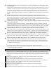
BEFORE USING THE PRODUCT, BE SURE TO READ THE FOLLOWING: To maintain the safety: To ensure the safe usage of the product, be sure to read the following before using the product. The following instructions are intended for the users, operators and the personnel in charge of the operation of the product. After carefully reading and sufficiently understanding the warning displays and cautions, handle the product appropriately.
Specification changes (removal of equipment, conversion and addition) not designated by SEGA are not allowed. The parts of the product include warning labels for safety, covers for personal protection, etc. It is very hazardous to operate the product by removing parts and or modifying the circuits. Should doors, lids and protective parts be damaged or lost, refrain from operating the product, and contact where the product was purchased from or the office herein stated.
TABLE OF CONTENTS BEFORE USING THE PRODUCT, BE SURE TO READ THE FOLLOWING: TABLE OF CONTENTS INTRODUCTION OF THE OWNER’S MANUAL 1. HANDLING PRECAUTIONS ................................................................................................ 1 2. PRECAUTIONS CONCERNING INSTALLATION LOCATION ........................................ 2 - 3 3. OPERATION ........................................................................................................................... 4 - 5 4. NAME OF PARTS ......
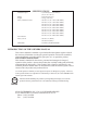
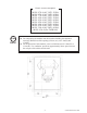
SPECIFICATIONS Installation Space Height Weight Power, maximum current For TAIWAN Power, current MONITOR : 1,310 mm (W) X 2,830 mm (D) (51.6 in. X 111.4 in.) : 2,660 mm (104.7 in.) : 370 kg. (815.7 lbs.) : 600 W 6.7 A (AC 110V 50 Hz AREA) 600 W 6.7 A (AC 110V 60 Hz AREA) 580 W 6.0 A (AC 120V 60 Hz AREA) 590 W 3.5 A (AC 220V 50 Hz AREA) 580 W 3.4 A (AC 220V 60 Hz AREA) 600 W 3.4 A (AC 230V 50 Hz AREA) 580 W 3.2 A (AC 230V 60 Hz AREA) 600 W 3.2 A (AC 240V 50 Hz AREA) 590 W 3.
DEFINITION OF LOCATION MAINTENANCE MAN AND SERVICEMAN Non-technical personnel who do not have technical knowledge and expertise should refrain from performing such work that this manual requires the location's maintenance man or a serviceman to carry out, or work which is not explained in this manual. Failing to comply with this instruction can cause a severe accident such as electric shock.
1. HANDLING PRECAUTIONS When installing or inspecting the machine, be very careful of the following points and pay attention to ensure that the player can enjoy the game safely. Non-compliance with the following points or inappropriate handling running counter to the cautionary matters herein stated can cause personal injury or damage to the machine. Before performing work, be sure to turn power off. Performing the work without turning power off can cause an electric shock or short circuit.
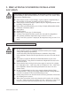
2. PRECAUTIONS CONCERNING INSTALLATION LOCATION This product is an indoor game machine. Do not install it outside. Even indoors, avoid installing in places mentioned below so as not to cause a fire, electric shock, injury and or malfunctioning. Places subject to rain or water leakage, or places subject to high humidity in the proximity of an indoor swimming pool and or shower, etc. Places subject to direct sunlight, or places subject to high temperatures in the proximity of heating units, etc.
Electric current consumption MAX. 8.70 A (AC 110V 50 Hz) MAX. 8.30 A (AC 110V 60 Hz) MAX. 7.70 A (AC 120V 60 Hz) MAX. 4.50 A (AC 220V 50 Hz) MAX. 4.30 A (AC 220V 60 Hz) MAX. 4.20 A (AC 230V 50 Hz) MAX. 4.00 A (AC 230V 60 Hz) MAX. 4.10 A (AC 240V 50 Hz) MAX. 3.90 A (AC 240V 60 Hz) MAX. 8.30 A (For TAIWAN) STOP IMPORTANT! For transporting the machine into the location's building, the minimum necessary dimensions of the opening (of doors, etc.) are 1.2m(W) and 1.7m(H).
3. OPERATION PRECAUTIONS TO BE HEEDED BEFORE STARTING THE OPERATION To avoid injury and trouble, be sure to constantly give careful attention to the behavior and manner of the visitors and players. In order to avoid accidents, check the following before starting the operation: Check if all of the adjusters are in contact with the surface. If they are not, the Cabinet can move and cause an accident.
PRECAUTIONS TO BE HEEDED DURING OPERATION (PAYING ATTENTION TO CUSTOMERS) To avoid injury and trouble, be sure to constantly give careful attention to the behavior and manner of the visitors and players. To avoid injury and accidents, those who fall under the following categories are not allowed to play the game. • Those who need assistance such as the use of an apparatus when walking. • Those who have high blood pressure or a heart problem.
4. NAME OF PARTS Accel.& Brake Pedal 29 inch monitor FRONT CABINET Clutch Pedal Steering Wheel Billboard Coin chute door Cashbox door REAR CABINET FIG. 4 a OVERVIEW 6-speed shift Effect switch AC unit FIG. 4 c REAR VIEW FIG. 4 b TABLE 4 FRONT CABINET REAR CABINET When assembled www.seuservice.
5. ACCESSORIES When transporting the machine, make sure that the following parts are supplied. The printer is available in this product as an optional. The printer prints Player's game results on the paper exclusively used for this product. Contact where you purchased the product from and mention the following Kit No. for an order. Detailed installation method is explained in the Kit Manual contained in the Kit. KIT NO.
VOL CONT B-5K OHM 220-5484 (1) 220-5373 Spare, see Section 9, 11, 12. SW MICRO TYPE 509-5387 (2) Spare, see Section 9. FUSE 6.3A 250W 514-5086-6300 (1) Spare, see Section 17. CARTON BOX 601-10577 (1) Used for transporting the Game Board. Refer to Next Page. TAMPERPROOF†SCREW 008-B00830-0B (2) Used for installing BILLBOARD. see 2 of Section 6. www.seuservice.com 8 SW MICRO TYPE 509-5636 (2) Spare, see Section 10.
HOW TO USE THE CARTON BOX When requesting for the replacement/repair of this product's Game Board (NAOMI BOARD), follow the instructions below. Transporting the Game Board in an undesignated status is unacceptable. An erroneous handling can cause parts damage. • Put the Game Board in the Carton Box together with the Shield Case. Do not unnecessarily disassemble nor remove parts. • By paying careful attention to the direction shown by the following Figure, put the Shield Case in the Carton Box.
6. ASSEMBLING AND INSTALLATION Perform assembly work by following the procedure herein stated. Failing to comply with the instructions can cause electric shock hazard. Perform assembling as per this manual. Since this is a complex machine, erroneous assembling can cause an electric shock, machine damage and or not functioning as per specified performance. When assembling, be sure to use plural persons.
When carrying out the assembling and installation, follow the following 6-item sequence.
1 ASSEMBLING THE CABINET 1 Install the Joint Bracket L and 2 Joint Bracket R to the both sides of Front Cabinet, and 2 Joint Pipes to the inside. At this time, temporarily install the Joint Brackets L and R. JOINT BRACKET R JOINT PIPE Hexagon Bolt(2 each) M8 X 30,w/spring washer, flat washer used. Hexagon Bolt(4 each) M8 X 20,w/spring washer, flat washer used. JOINT BRACKET L FIG. 6. 1 a Hexagon Bolt(2) M8 X 30,w/spring washer, flat washer used. Connect the Earth.
3 Insert the Front Cabinet's Joint pipes into the Rear Cabinet's square holes to fit both cabinets tight. Be sure to perform this work by 2 or more workers. Also, be careful so as not to pinch the wiring. 4 Secure the joint portion of the Cabinets with 6 Hexagon Bolts. Firmly secure the Joint Brackets L&R, respectively. 5 By using Joint Plate Center, secure the joint portion of the Cabinets with 4 Truss screws and Hexagon Bolts.
2 INSTALLING THE CENTER ROOF AND THE BILLBOARD 1 Put the Center Roof on its installation position. 2 Put each of Roof Nut Plates F & R on to the fixed portion of the Center Roof front and rear and secure with 3 Truss screws for each. 3 Remove the Shipping Bracket Rear from the Rear Cabinet's ceiling. Remove the 2 pairs of Tamperproof screws and Hexagon Bolts.
3 SECURING IN PLACE (ADJUSTER ADJUSTMENT) Make sure that all of the adjusters are in contact with the floor. If they are not, the cabinet can move and cause an accident. This product has 8 casters (4 for Front Cabinet, 4 for Rear Cabinet) and 8 Adjusters (4 for Front Cabinet, 4 for Rear Cabinet). (FIG. 6. 3a) When the installation position is determined, cause the adjusters to come into contact with the floor directly, make adjustments in a manner so that the casters will be raised approximately 5mm.
4 POWER SUPPLY, AND EARTH CONNECTION Be sure to independently use the power supply socket outlet equipped with an Earth Leakage Breaker. Using a power supply without an Earth Leakage Breaker can cause a fire when electric leakage occurs. Ensure that the "accurately grounded indoor earth terminal" and the earth wire cable are available (except in the case where a power cord plug with earth is used). This product is equipped with the earth terminal.
2 Connect one end of the earth wire to the AC Unit Connect the Earth Wire to the Earth Terminal. earth terminal, and the other end to the indoor earth terminal. The AC Unit earth terminal has a Bolt and Nut combination. Take off the Nut, pass the end of earth wire through the Bolt, and fasten the Nut. Note that the Earth Wire is incorporated in the Power Cord for the Areas of AC 120V (USA) and AC 220Å`240V, and therefore, this procedure is not necessary. FIG. 6.
5 TURNING POWER ON Turn the Main SW of AC Unit ON to turn power on. When the power is turned on, the fluorescent lamps of the left & right of Seat in the Rear cabinet, the back, and the inside the Billboard light up. The screen displays the starting of Naomi System and then proceeds to ADVERTISE mode. During this time, the machine automatically performs Power On check. Do not touch the machine until Power On check is finished and ADVERTISE mode is displayed on the screen.
6 ASSEMBLING CHECK In the TEST mode, ascertain that the assembly has been made correctly, IC BD. is satisfactory, and the screen adjustment is appropriate. For details, refer to the SERVICE MANUAL. In the test mode, perform the following test: • MEMORY TEST The on-board memory is tested automatically. • CRT TEST The screen on which the monitor is adjusted is displayed. • INPUT TEST Each switch and V.R. are tested. • OUTPUT TEST The lamp, motor, etc. are tested.
7. PRINTER (OPTIONAL) Refer to this section only when the Printer (optional) is attached. Be sure to turn off power unless otherwise specified before performing work. Performing work on the energized machine can cause hands or fingers to be pinched in or in jured due to the machine's sudden move. Do not touch undesignated places. Failure to observe this may cause a burn due to the Head's high temperature when printing.
DIP SW SETTING SW1 The Printer has 2 DIP Switches. To avoid malfunctioning, use the Switches as adjusted at the time of shipment. SW 2 Setting at the time of shipment DIP SW FIG. 7. 1 7 -2 SETTING THE ROLL PAPER The 2 red Lamps at the Rear Cabinet back side flash indicating the PAPER END Error under normal operation. Prepare the new Roll Paper exclusively used for the product and the Master Key. To set the Roll Paper, perform Printer's initialization to remove the cause of the error.
4 Pull up the Head Up Lever. 5 Take out the roll shaft from the Printer. 6 Pass the shaft through the core of the new Roll Paper. 7 Install the roll shaft in which the paper is inserted into the unit. Make sure to put the Roll Paper on to the correct position. Roll shaft New Roll Paper Head Up Lever FIG. 7. 2 c 8 Insert the paper tip in to the roll paper insertion slot. Feed the Roll Paper tip through the exit slot straight by hand.
10 Select and execute the INIT in the PRINTER TEST PRINTER TEST. The "PRINTER INIT!!" message flashes next to "MESSAGE" on the monitor and then goes off. The Printer's initialization is finished. MESSAGE : PRINTER INIT! ERROR : WARNING : STATUS : COUNTER : -> INIT F-FEED B-FEED POSITION SET 11 Select and execute the "POSITION SET." "NOW PRINTING" message is displayed next to the "MESSAGE" on the monitor and then goes off.
Roll shaft New Roll Paper Note that this Roll Paper holder will not be seen when setting the new Paper for the first time. FIG. 7. 2 h Head Up Lever 8 Insert the paper tip in to the Roll Paper insertion slot. Feed the Roll Paper tip through the exit slot straight by hand. At this time, if the Paper tip is in excess of the feeding point, the automatic feeding of Paper is performed and the Paper is cut after feeding about one page long. 9 Push down the Head Up Lever.
7 - 3 CLEANING OF THE PRINTER HEAD Each time the Roll Paper is supplied, clean the Printer Head. Prepare the cleaning pen which is included in the Print Paper Set exclusively used for this product and a Master Key. 1 Turn off power. Roll Paper 2 Unlock with the Master Key and remove the Printer Door. 3 Draw the ASSY Printer toward you. Auto Cutter 4 Push up the Head Up Lever. 5 Remove the Roll Paper. 6 Push down the Cutter Lever and open the Auto Cutter. Head Up Lever Cutter Lever FIG. 7.
7 - 4 COUNTERMEASURES AGAINST PAPER JAM Prepare a Master Key and scissors or a knife for eliminating the warped, wrinkled paper due to paper jam. To perform the following work, turning off power is necessary for 2 reasons. One is that performing work on the energized Cabinet may cause hands and fingers to be injured due to unexpected move of the cutter or the motor. To avoid such an unforeseen accident, be sure to turn off power before performing work.
8. PRECAUTIONS TO BE HEEDED WHEN MOVING THE MACHINE When moving the machine, be sure to unplug the power plug. Moving the machine with the plug as is inserted can damage the power cord and cause fire and electric shock hazards. When moving the machine on the floor, retract the Adjusters and ensure that Casters make contact with the floor. During transportation, pay careful attention so that Casters do not tread power cords and earth wires.
When transporting the product in places with steps or step-like differences in grade, disassemble into each unit before transporting.
Precautions concerning applying a rope. SHIPPING BRACKET REAR FIG. 8 d • Do not apply a rope to Handle or Lever. • Use protective materials to the places the rope is applied to. Caution when transporting the machine FIG. 8 e 29 www.seuservice.
9. HANDLE MECHA Before starting to work, ensure that the Power SW is OFF. Failure to observe this can cause electric shock or short circuit. Use care so as not to damage wirings. Damaged wiring can cause electric shock or short circuit. Do not touch undesignated places. Touching places not designated can cause electric shock or short circuit. This work should be performed by the Location's Maintenance Man or Serviceman. Performing work by non-technical personnel can cause electric shock hazard.
3 Perform the adjustment while another person is securing the Steering Wheel in the centering position. 4 The V.R. is on the VR BASE (a white, plastic made part). Loosen the 2 screws which secure the VR BASE and adjust the angle and appropriateness of gear mesh by moving the VR BASE. 5 Adjust to an appropriate mesh by securing the Steering Wheel in the direction allowing the car to advance straight forward and ensuring the "D" CUT FACE of the Volume shaft is oriented as shown.
REPLACING THE VOLUME SCREW (2) M4 X 12,w/flat & spring washers 1 Disconnect the connector from the Volume. 2 Take out 2 screws to remove the Volume together with VR BASE from the HANDLE MECHA. VR BASE PHOTO 9. 1 b 3 Take out 2 screws from the VR BASE reverse side to remove the Volume together with VR Bracket from the VR BASE. 4 Remove the Volume from VR Bracket and replace. TRUSS SCREW (2) M4 X 12 PHOTO 9. 1 c www.seuservice.
5 After replacing the Volume, engage the gears at the angular position shown and fix the VR Bracket. VR BASE SCREW(2) M4 X 12,w/flat & spring washers FIG. 9. 1 b 6 Turn on power. V.R. 220-5484 220-5373 7 Set the Center Value of the Volume in the TEST mode. 8 In the TEST mode, check to see if the Volume Value varies smoothly in accordance with the steering wheel operation. 9 - 2 GREASING STOP IMPORTANT! Be sure to use the designated grease. Using undesignated grease can cause parts damage.
9 - 3 REPLACING PADDLE (WING) SHIFT SWITCH In case the Paddle Shift operability is poor, malfunctioning of or a damage to the Microswitch inside the Paddle Shift can be considered. 1 Turn off power. BOSS COVER PADDLE SHIFT 2 Take out 2 Truss screws for each to remove Boss Cover Upper and Lower. 3 Disconnect the wiring connected to the Microswitch. TRUSS SCREW (2 each) M4 X 8 BOSS COVER PHOTO 9. 3 a www.seuservice.
SCREW (2) M3 X 16 4 Take out 2 screws to replace the Microswitch. 5 Adjust Microswitch's actuator to an angular position so as not to touch the Switch when operating the Shift Lever. 6 Fasten 2 screws to secure the Microswitch. 7 Check to ensure that the Switch goes ON and OFF in consistency with the operation. MICROSWITCH 509-5387 PHOTO 9. 3 b 35 www.seuservice.
10. 6-SPEED SHIFT Before starting to work, ensure that the Power SW is OFF. Failure to observe this can cause electric shock or short circuit. Use care so as not to damage wirings. Damaged wiring can cause electric shock or short circuit. Do not touch undesignated places. Touching places not designated can cause electric shock or short circuit. This work should be performed by the Location's Maintenance Man or Serviceman. Performing work by non-technical personnel can cause electric shock hazard.
4 Disconnect a connector. 5 Take out 4 Hexagon Bolts. HEXAGON BOLT (4) M8 X 40,w/flat & spring washers Disconnect the connector PHOTO 10. 1 b 6-SPEED SHIFT PHOTO 10. 1 c 6 Lift the 6-speed Shift vertically. At this time, use care so as not to hang the wiring or hit the other parts. 7 Disconnect 2 connectors to remove the 6-speed Shift. PHOTO 10. 1 d Disconnect the connector 37 www.seuservice.
10 - 2 REPLACING THE SWITCH In case 6-speed Shift operability is poor, malfunction of or damage to the Microswitch of Mechanism can be considered. The 6-speed Shift has 4 Microswitches. Be sure to check which Switch malfunctions prior to performing work. 1 Remove 6-speed Shift as per procedure 10-1. SCREW (2) M2.3 X 10,w/flat & spring washers 2 Disconnect the wiring connected to the Microswitch. 3 Take out 2 screws to replace the Microswitch.
11. ACCELERATOR & BRAKE Before starting to work, ensure that the Power SW is OFF. Failure to observe this can cause electric shock or short circuit. Use care so as not to damage wirings. Damaged wiring can cause electric shock or short circuit. Do not touch undesignated places. Touching places not designated can cause electric shock or short circuit. This work should be performed by the Location's Maintenance Man or Serviceman.
REPLACING THE VOLUME TRUSS SCREW (2) M4 X 8 POTENTIOCOVER 1 Turn the power off. 2 Take out the 2 screws and remove the Potentiocover (FIG. 11. 1 c). 3 Disconnect the connector of the Volume to be replaced. 4 Remove the screw which secures the Potentiobase (FIG. 11. 1 b). 5 Remove the Potentiobase together with the Volume as is attached. (FIG. 11. 1 c) 6 Remove the Base and Gear to replace the Volume. 7 Adjust the Volume as per the previous page after replacing. 11 - 2 GREASING STOP FIG. 11.
12. CLUTCH PEDAL Before starting to work, ensure that the Power SW is OFF. Failure to observe this can cause electric shock or short circuit. Use care so as not to damage wirings. Damaged wiring can cause electric shock or short circuit. Do not touch undesignated places. Touching places not designated can cause electric shock or short circuit. This work should be performed by the Location's Maintenance Man or Serviceman. Performing work by non-technical personnel can cause electric shock hazard.
3 Take out a screw to remove the earth wire which is connected to the Clutch Pedal Mechanism side. SCREW (1) M4 X 8,w/flat & spring washers EARTH PHOTO 12. 1 b 4 Disconnect the connector to remove the Clutch Pedal. Disconnect the connector PHOTO 12. 1 c www.seuservice.
12 - 2 VOLUME ADJUSTMENT/REPLACEMENT The appropriate value of Crutch Volume is under 30H when released and over C0H when stepped on. Check Volume values in the TEST mode. Since work is performed inside the energized cabinet, be very careful so as not to touch undesignated places. Touching places not specified can cause electric shock or short circuit. ADJUSTING THE VOLUME 1 Loosen 2 screws which secure the Volume Bracket to adjust the gear mesh. 2 Tighten the 2 screws.
12 - 3 GREASING STOP Be sure to use the designated grease. Using undesignated grease can cause parts damage. IMPORTANT! Once every 3 months, apply greasing to the Spring and Gear mesh portion. For spray greasing, use GREASE MATE (PART No. 090-0066). VOLUME GEAR MESH PORTION SPRING SPRING PHOTO 12. 3 www.seuservice.
13. COIN SELECTOR HANDLING THE COIN JAM If the coin is not rejected when the REJECT button is pressed, open the coin chute door and open the selector gate. After removing the jammed coin, put a normal coin in and check to see that the selector correctly functions. CLEANING THE COIN SELECTOR GATE STOP IMPORTANT! Remove and clean smears by using a soft cloth dipped in water or diluted chemical detergent and then squeezed dry. Never apply machine oil, etc. to the Coin Selector.
www.seuservice.com 46 K L 29 7 5 J 5 C 1 B 2 5 28 17 F 18 D G 27 E H A M 14 6 12 26 2701 N. KILDARE CHICAGO, IL 60639 1-800-336-6630 WWW.WGEC.
47 www.seuservice.com Tom Happ Ph: 847-593-6161 ext. 107 tom.happ@happcontrols.com Fx: 847-956-2091 Happ Controls, 106 Garlisch Drive, Elk Grove, IL 60007 Visit our website http://www.happcontrols.
OPTIONAL DOLLAR BILL ACCEPTOR THE COIN DOOR ASSEMBLY USED ON F355 challenge DX TYPE COMES EQUIPPED TO ACCEPT A DOLLAR BILL ACCEPTOR. ALL NEEDED WIRING CONNECTIONS ARE CONVIENENTLY LOCATED INSIDE THE GAME FOR THIS APPLICATION. THE COIN DOOR CAN ACCCOMMODATE THE FOLLOWING VALIDATOR(S): FORWARD-MOST HOLE POSITION **42-1155-00 Mars 2000 series MARS VALIDATOR $1, 2, 5 300 CAP The frame and cashbox enclosure on this coindoor has been modified to accomodate a Mars 2000 series upstacker.
14. MONITOR 14 - 1 CAUTIONS AND WARNINGS CONCERNING THE SAFETY FOR HANDLING THE MONITORS Before handling the monitors, be sure to read the following explanations and comply with the caution/warning instructions given below. Note that the caution/warning symbol marks and letters are used in the instructions. Indicates that handling the monitors erroneously by disregarding this warning may cause a potentially hazardous situation, which could result in death or serious injury.
Static Electricity Touching the CRT surface sometimes causes you to slightly feel electricity. This is because the CRT surfaces are subject to static and will not adversely affect the human body. Installation and removal Ensure that the Magnetizer Coil, FBT (Fly-Back Transformer), Anode Lead and Focus Lead are not positioned close to the sheet metal work's sharp edges, etc. and avoid damaging the insulated portions so as not to cause electric shock and malfunctioning.
For the purpose of static prevention, special coating is applied to the CRT face of this product. To protect the coating, pay attention to the following points. Damaging the coating film can cause electric shock to the customers. Do not apply or rub with a hard item (a rod with pointed edge, pen, etc.) to or on the CRT surfaces. Avoid applying stickers, seals, etc. on the CRT face. Aluminum Foil Do not remove aluminum foils from the CRT corners.
14 - 3 ADJUSTMENT METHOD Monitor adjustments have been made at the time of shipment. Therefore, do not make further adjustment without a justifiable reason. Adjusting the monitor which contains high tension parts is a dangerous work. Also, an erroneous adjustment can cause deviated synchronization and image fault, resulting in malfunctioning. When making adjustment, utilize a resinous Alignment Rod. Servicing with bare hand or using conductive tools can cause electric shock.
OPERATION 1 Press the MODE button to display OSD. The right-hand end numeral indicates INPUT FREQUENCY. Example: 31 kHz Input V-POSI 31 051 IN/OUT/MODE DOWN UP OSD Display 2 Press the MODE button to select the adjustment item. (Each time the MODE button is pressed, the OSD display shifts sequentially in order of V-POSI Å® H-POSI Å® V-SIZE Å® H-SIZE Å® CONTRAST Å® BRIGHT Å® DEGAUSS Å® RESET Å® OSD display disappears.
14 - 4 CLEANING THE MONITOR GLASS Removing the Monitor Glass requires complicated work. Clean the Front Glass only in the weekly cleaning. To clean the Reverse Glass of the Monitor and the CRT Surface, removing the Monitor Glass is required. FRONT MONITOR GLASS 1 Take out 2 screws to remove the Boss Cover. 2 Take out 10 screws to remove the Control Panel Upper. If it is hard to take out the screws due to the existence of the Steering Wheel, remove the emblem and the Steering Wheel ahead of time.
BOTH SIDE MONITOR GLASS 1 Take out 9 screws and remove Monitor Cover. TRUSS SCREW(9 in total),chrome M4 X 10,flat washer used MONITOR COVER PHOTO 14. 4 a 2 Take out 3 screws and remove Monitor Side Cover. MONITOR SIDE COVER TRUSS SCREW(3),black M4 X 8 PHOTO 14. 4 b 55 www.seuservice.
3 Take out 2 screws to remove the Side Cover Bracket. SIDE COVER BRACKET PHOTO 14. 4 c SCREW(2) M4 X 8,w/flat & spring washers MONITOR BOARD LID 4 Take out 2 screw to remove the Monitor Board Lid. 5 Pull out the Monitor Glass. PHOTO 14. 4 d MONITOR GLASS www.seuservice.
15. REPLACING THE FLUORESCENT LAMP, AND LAMPS The Error Lamp is used when the Printer (optional) is incorporated. If the Printer (optional) is not incorporated, disregard the following explanation of replacing the ERROR LAMP. Regarding the U.S. Specifications: The parts employed for the U.S. Specifications machines are procured in the U.S.A. Therefore, the parts in the U.S. Specifications are different from those of described in this section or listed in the PARTS LIST.
SEAT LEFT & RIGHT 1 Turn off power. 2 Take out 5 Truss screws from the left-hand side and 4 Truss screws from the right-hand side of the seat facing the monitor. 3 Remove the Sash. 4 Remove the FL Cover Side. 5 Replace the Fluorescent Lamp. SASH TRUSS SCREW (4) M4 X 12 TRUSS SCREW (5) M4 X 12 LEFT RIGHT FLUORESCENT LAMP 32W :390-5251-32-01 GLOW BULB: 390-5638-5P www.seuservice.com FL COVER SIDE 58 FIG.
1 Turn off power. BILLBOARD 2 Take out 4 Truss screws in total. 3 Remove 2 Bushes and the Plate Holder. 4 Remove the FL Plate. At this time, be sure to keep TRUSS SCREW (2) M4 X 16 the washers used underneath the Bushes. 5 Replace the Fluorescent Lamp. TRUSS SCREW (2) M4 X 16 BUSHE FL PLATE WASHER M4 FIG. 15 b PLATE HOLDER FLUORESCENT LAMP 20W: 390-5251-20-01 GLOW BULB: 390-5638-1E When performing work, be sure to use a step. 59 www.seuservice.
THE REAR SIDE 1 Turn off power. 2 Take out 8 Truss screws. TRUSS (8)M4 X 12,flat washer used. 3 Remove the FL Cover Rear. 4 Replace the Fluorescent Lamp. PHOTO 15 a FL COVER REAR FLUORESCENT LAMP 30W: 390-5251-30-01 GLOW BULB: 390-5638-1E PHOTO 15 b www.seuservice.
SLIM LAMP SASH REAR 1 Remove the FL Cover Rear as per procedures in THE REAR. 2 Take out 4 screws of the FL Cover Rear installing portion where the Slim lamp to be replaced is attached. SCREW (4)M4 X 16,w/flat & spring washers 3 Remove the Sash Rear. 4 Take out 2 screws. 5 Remove the Rear Window. PHOTO 15 c REAR WINDOW TRUSS SCREW (2) M4 X 12 PHOTO 15 d 61 www.seuservice.
6 Remove the Corner Plate. When it is hard to remove the Corner Plate, loosen the 5 screws which secure the Corner Light Lid. CORNER LIGHT LID SLIM LAMP 390-6651 PHOTO15 e CORNER PLATE 7 Take out 2 screws which secure the Bracket of connector side of the Slim lamp. CONNECTOR 8 Disconnect the connector and replace the Slim lamp. 9 Insert the edge of the replacing Slim lamp in to the holder. 10 Pass the plastic made bush and spacer through the 2 screws which secure the Bracket of the connector side.
ERROR LAMP To perform the following work, a Phillips type Screwdriver and a driver for M4 Hexagon Nut are required. ÇVmm 1 Turn off power. 2 Take out 2 screws. 3 Remove the Socket Cover. SCREW (2) M4 X 8 SOCKET COVER PHOTO 15 f 4 Disconnect a connector. Disconnect the connector PHOTO 15 g 63 www.seuservice.
5 Take out 2 Flange Nuts. 6 Remove the Lamp together with the Lamp Base. FLANGE NUT (2) M4 LAMP BASE PHOTO 15 h 7 Replace the Lamp. LAMP 110V 10W 390-5174 PHOTO 15 i www.seuservice.
REPLACING THE EFFECT SWITCH LAMP 1 Remove the Shift Cover as per procedures 10-1. Unlock the lock 2 A metallic part is ejected from the switch base of the EFFECT SWITCH reverse side. Turning the metallic part can unlock the lock. Take off the wiring connecting portion from the switch. PHOTO 15 j PHOTO 15 k 3 The lamp is inside the wiring connecting portion. Push and then turn the Lamp counterclockwise to remove. LAMP 6.3V 1W 390-5445-01 PHOTO 15 l 65 www.seuservice.
16. PERIODIC INSPECTION TABLE The items listed below require periodic check and maintenance to retain the performance of this machine and to ensure safe business operation. Be sure to check once a year to see if Power Cords are damaged, the plug is securely inserted, dust is accumulated between the Socket Outlet and the Power Plug, etc. Using the product with dust as is accumulated can cause fire and electric shock hazards.
REAR CABINET (Greasing to Seat Rail Portion) Move the Seat to the rearmost portion and apply spray greasing to the portion shown at the right once every 3 months by using NOK KLUBER L60 or GREASE MATE SEGA PART No. 090-0066. After greasing, move the Seat a few times forward and backward so as to allow the grease to be applied all over uniformly. Be sure to wipe grease which attaches to the surfaces of the PROTECT RUBBER on the Seat Rail, or any excess grease. FIG.
17. TROUBLESHOOTING In case a problem occurs, first check wiring connector connections. WARNING! In order to prevent electric shock and short circuit, be sure to turn power off before performing work. Be careful so as not to damage wirings. Damaged wiring can cause electric shock or short circuit. After removing the cause of the functioning of the Circuit Protector, reinstate the Circuit Protector.
TABLE 17 b PROBLEMS CAUSE COUNTERMEASURES No sound is emitted from WOOFER. The Fuse is blown due to momentary overload. Replace fuse. (see FIG. 17 c) 514-5086-6300 FUSE 6.4Å~30 6300mA 125W Steering Wheel reaction strength is incorrect. Deviation of Center. Power ON check not performed correctly. Turn off power and then turn it back on again. Complete the power on check. V.R. position deviated. Adjust V. R. value in the test mode. (see Service Manual) V.R. malfunctioning. Replace V.R. (see Sec.
REPLACMENT OF FUSE Fuse replacements other than those specified can cause accidents and are strictly forbidden. In case fuse replacements other than those stated in this manual are necessary, contact where you purchased the product from for inquiries regarding this matter. In order to prevent an electric shock, be sure to turn power off and unplug from the socket outlet before performing work by touching the internal parts of the product. Be careful so as not to damage wirings.
18. GAME BOARD In order to prevent electric shock and short circuit hazards, be sure to turn power off before performing work. Be careful so as not to damage wirings. Damaged wiring can cause fire, electric shock and short circuit hazards. Do not expose the Game BD, etc. without a good reason. Failure to observe this can cause electric shock or malfunctioning. The electronic parts on the IC Board could be damaged due to human body's static electricity.
CONNECTING THE VIDEO SIGNAL LINE AND AUDIO SIGNAL LINE MONITOR LEFT (RGB3) SPEAKER (AUDIO1) MONITOR RIGHT (RGB4) FIG. 18. 1 b SPEAKER (AUDIO2) MONITOR CENTER (RGB2) 18 - 2 COMPOSITION OF GAME BOARD GAME BD FRI DX USA (833-13841-01) GAME BD FRI DX EXP (833-13841-02) GAME BD FRI DX KOR (833-13841-03) GAME BD FRI DX AUS (833-13841-04) : : : : USA OTHERS KOREA AUSTRALIA PHOTO 18. 2 DIP SW SETTING ON In the product, set all of the DIP SWes to OFF. 1 2 3 4 FIG. 18. 2 www.seuservice.
19. DESIGN RELATED PARTS For the Warning Display stickers, refer to Section 1.
20. PARTS LIST 1 TOP ASSY FRI DX www.seuservice.
1 TOP ASSY FRI DX ITEM NO. ( D-2/3 ) PART NO.
1 TOP ASSY FRI DX / / / / / / / / PART NO. DESCRIPTION 105-5356 421-8740 280-6609 421-6690-06 421-6690-03 421-6690-05 421-6690-01 421-7308 ~ SHIPPING BRKT CAUTION INSTR COP U/R REPEAT TIE RF140 STICKER 110V STICKER 220V STICKER 240V STICKER 120V DENOMI SH 1GAME ~ 421-6119-91 421-6120-91 STICKER FCC STICKER SEGA USA www.seuservice.com 76 NOTE AC 110V AREA AC 220V AREA AC 240V AREA AC 120V AREA 1 2 3 ITEM NO.
( D-1/3 ) NOTE) M8 BOLT FASTENING TORQUE TO BE:178kgf•cm 2 ASSY FRONT CABINET (FRI-1000) 77 www.seuservice.
2 ASSY FRONT CABINET (FRI-1000) ITEM NO. 1 2 3 4 5 6 7 8 9 10 13 14 15 16 17 18 19 20 21 22 23 24 25 26 27 28 29 30 31 32 33 34 35 36 37 38 41 42 43 44 45 46 47 48 49 50 51 52 53 55 56 57 58 59 ( D-2/3 ) PART NO.
2 ASSY FRONT CABINET (FRI-1000) ITEM NO. ( D-3/3 ) PART NO.
3 ASSY REAR CABINET (FRI-3000) www.seuservice.
3 ASSY REAR CABINET (FRI-3000) ( D-2/2 ) ITEM NO. PART NO.
4 ASSY BILLBOARD (FRI-0500) NOTE) M8 TAMPER FASTENING TORQUE TO BE: 30kgf•cm ITEM NO. 1 2 201 202 PART NO. DESCRIPTION FRI-0501 FRI-0502 BILLBOARD BILLBOARD LEG 008-B00830-0B 068-852216-0B TMP PRF SCR BH BLK M8 X 30 FLT WSHR BLK 8.5-22 X 1.6 www.seuservice.
( D-1/3 ) M8 BOLT FASTENING TORQUE TO BE:178kgf•cm 5 ASSY FRONT SUB-CABI (FRI-1001) 83 www.seuservice.
5 ASSY FRONT SUB-CABI (FRI-1001) ITEM NO. 1 2 3 4 5 6 7 8 9 10 11 12 13 14 15 16 17 18 19 20 21 22 23 24 25 26 27 28 29 30 31 32 101 102 103 104 105 106 107 108 109 110 111 ( D-2/3 ) PART NO.
5 ASSY FRONT SUB-CABI (FRI-1001) ITEM NO. ( D-3/3 ) PART NO. DESCRIPTION 201 202 203 204 205 206 207 208 209 210 211 212 213 214 215 216 217 218 000-P00416-W 000-T00420-0B 000-T00430-0B 011-F00310 011-T00312 011-T03512 030-000630-SB 030-000830-SB 050-H01600 060-F00600-0B 060-F00800-0B 068-441616-0B 011-F03516 FAS-110010 000-P00408-S 050-H00400 060-S00400 060-F00400 M SCR PH W/FS M4 X 16 M SCR TH BLK M4 X 20 M SCR TH BLK M4 X 30 TAP SCR FH 3 X 10 TAP SCR TH 3 X 12 TAP SCR TH 3.
6 AC UNIT (FRI-1020) www.seuservice.
6 AC UNIT (FRI-1020) 1 2 3 4 5 ( D-2/2 ) FRI-1021 421-7468-01 421-8202 FRI-1022 421-7515 AC BRACKET STICKER C.P W/PIC STICKER EARTH MARK CONNECTOR LID STICKER FIBER CABLE TX/RX 106 107 108 109 110 214-0202 280-0417 509-5453-91-V-B 512-5046-15000 512-5046-8000 450-5126 450-5134 450-5135 270-5081 280-5009-01 310-5029-G20 601-0460 211-5479-01 AC INLET PANEL TYPE TERMINAL BINDING POST BLACK SW ROCKER J8 V-B C.P 15000MA CE UL C.
7 SW UNIT (FRI-1030) ITEM NO. PART NO. DESCRIPTION 1 2 FRI-1031 421-11127 SW BRACKET STICKER SW UNIT 101 102 103 104 105 220-5179 509-5028 601-0042 310-5029-D20 601-0460 VOL CONT B-5K OHM SW PB 1M KNOB 22 MM SUMITUBE F D 20 MM PLASTIC TIE BELT 100 MM 301 302 303 APC-60087 600-6609-32 FRI-60089 WIRE HARN DEMAG WIRE HARN TEST & SERVICE WIRE HARN SOUND VOL www.seuservice.
8 FAN MOTOR UNIT (APC-1035) Connector ITEM NO. PART NO. DESCRIPTION 1 APC-1036 FAN MOTOR BRKT 101 102 260-0011-02 601-8543 AXIAL FLOW FAN AC100V 50-60HZ FAN GUARD 201 202 000-P00312-W 050-F00300 M SCR PH W/FS M3 X 12 FLG NUT M3 89 NOTE www.seuservice.
9 METER UNIT S (APC-1040) ITEM NO. PART NO. DESCRIPTION 1 2 APC-1041 421-6591-16 METER BRKT S STICKER COIN METER \100 101 220-5643-01 MAG CNTR DC5V 6P WH MZ-674-D04 www.seuservice.
9 METER UNIT T (APC-1040-01) ITEM NO. PART NO. DESCRIPTION 1 2 APC-1042 421-6591-01 METER BRKT T STICKER COIN METER 101 102 220-5643-01 220-5643-02 MAG CNTR DC5V 6P WH MZ-674-D04 MAG CNTR DC5V 6P YE MZ-674-D05 91 NOTE www.seuservice.
10 FAN UNIT (STR-1070) Connector ITEM NO. PART NO. DESCRIPTIONNOTE 1 105-5340-01 FAN BRKT LONG 101 102 260-0011-02 601-8543 AXIAL FLOW FAN AC100V 50-60HZ FAN GUARD 201 000-P00312-W M SCR PH W/FS M3 X 12 www.seuservice.
11 ASSY WIRE FRONT CABI AC (FRI-6001) ASSY WIRE FRONT CABI AC is comprised of the following wire harnesses. An ASSY DRG. is unavailable. ITEM NO. PART NO. DESCRIPTION 101 601-0460 PLASTIC TIE BELT 100 MM 301 302 303 304 FRI-60045 FRI-60046 FRI-60047 FRI-60061 WIRE HARN EXT AC MONITOR WIRE HARN EXT AC REAR WIRE HARN EXT AC FRONT WIRE HARN EXT SERVO PWR NOTE 12 ASSY WIRE FRONT CABI DC (FRI-6002) ASSY WIRE FRONT CABI DC is comprised of the following wire harnesses. An ASSY DRG. is unavailable.
14 ASSY MONITOR CENTER (APC-1100) ITEM NO. PART NO.
( D-1/2 ) Details of PART A 15 ASSY MONITOR LEFT (APC-1150) 95 www.seuservice.
15 ASSY MONITOR LEFT (APC-1150) ITEM NO. ( D-2/2 ) PART NO.
( D-1/2 ) Details of PART A 16 ASSY MONITOR RIGHT (APC-1200) 97 www.seuservice.
16 ASSY MONITOR RIGHT (APC-1200) ITEM NO. ( D-2/2 ) PART NO. DESCRIPTION 1 2 3 4 5 6 7 8 9 10 11 12 13 14 15 16 APC-1151 APC-1152X APC-1153X APC-1154X APC-1155X APC-1156X APC-1157X APC-1054 APC-1159X APC-1058X 280-5112 280-5113 APC-1083 601-10562-0170 601-10562-0580 APC-1086 MONITOR FRAME MONITOR HOLD UPPER MONITOR HOLD LOWER SIDE COVER BRKT SIDE BRKT GLASS HOLDER UPPER SIDE GLASS HOLDER LOWER SIDE GLASS MONITOR SIDE COVER MONITOR BD LID BUSH FOR TV COLLAR FOR TV MONITOR MASK RUBBER PACKING NO.
17 ASSY STEERING MECHA (FRI-2000) ( D-1/2 ) TORQUE 99 www.seuservice.
17 ASSY STEERING MECHA (FRI-2000) ITEM NO. PART NO.
SCREW FASTENING TORQUE TO BE Details of PART B ( D-1/2 ) ACTUATOR 18 ASSY PADDLE SHIFT (FRI-2050) 101 www.seuservice.
18 ASSY PADDLE SHIFT (FRI-2050) ( D-2/2 ) ITEM NO. PART NO.
( D-1/2 ) Apply greasing SCREW FASTENING TORQUE TO BE 19 STEERING MOTOR UNIT (FRI-2100) 103 www.seuservice.
19 STEERING MOTOR UNIT (FRI-2100) ( D-2/2 ) ITEM NO. PART NO.
20 PEDAL UNIT (FRI-2200) SCREW FASTENING TORQUE TO BE ITEM NO. 1 2 3 4 201 202 203 204 205 PART NO. DESCRIPTION FRI-2250 FRI-2300 FRI-2201 FRI-2204 ASSY ACCEL&BRAKE ABSORBER UNIT FOOT REST FRI PEDAL BASE 030-000825-SB 060-F00800-0B 050-H00800 060-S00800 060-F00800 HEX BLT W/S BLK M8 X 25 FLT WSHR BLK M8 HEX NUT M8 SPR WSHR M8 FLT WSHR M8 105 NOTE www.seuservice.
21 ASSY ACCEL&BRAKE (FRI-2250) www.seuservice.
21 ASSY ACCEL&BRAKE (FRI-2250) ( D-2/2 ) ITEM NO. PART NO.
22 ABSORBER UNIT (FRI-2300) SCREW FASTENING TORQUE TO BE ITEM NO. PART NO. DESCRIPTION 1 2 3 4 5 FRI-2301 FRI-2302 FRI-2303 FRI-2305 FRI-2306 ABSORBER BRKT ABSORBER SUB BRKT PLUNGER COMP SPRING FRI STOPPER SHAFT 101 601-10662 SHOCK ABSORBER W/O CAP 201 202 203 204 205 030-000825-SB 060-F00800-0B 060-S00600 050-U00600 068-652016 HEX BLT W/S BLK M8 X 25 FLT WSHR BLK M8 SPR WSHR M6 U NUT M6 FLT WSHR 6.5-20 X 1.6 www.seuservice.
Apply greasing to gear mesh portions and spring portions. 23 CLUTCH UNIT (FRI-2400) ( D-1/2 ) 109 www.seuservice.
23 CLUTCH UNIT (FRI-2400) ITEM NO. ( D-2/2 ) PART NO.
24 ASSY REAR SUB-CABI (FRI-3001) ( D-1/2 ) 111 www.seuservice.
24 ASSY REAR SUB-CABI (FRI-3001) ITEM NO. ( D-2/2 ) PART NO.
25 ASSY WIRE REAR (FRI-6003) ASSY WIRE REAR is comprised of the following wire harnesses. An ASSY DRG. is unavailable. ITEM NO. PART NO. DESCRIPTION 101 601-0460 PLASTIC TIE BELT 100 MM 301 302 303 304 305 FRI-60065 FRI-60066 FRI-60067 FRI-60070 FRI-60073 WIRE HARN EXT REAR CTRL B WIRE HARN EXT SHIFT LOCK B WIRE HARN EXT SEAT SP B WIRE HARN EXT BASS SP WIRE HARN EXT BRAKE LAMP B 113 NOTE www.seuservice.
26 ASSY 6SPEED SHIFTER (FRI-2150) www.seuservice.
26 ASSY 6SPEED SHIFTER (FRI-2150) ITEM NO. ( D-2/3 ) PART NO.
26 ASSY 6SPEED SHIFTER (FRI-2150) ITEM NO. ( D-3/3 ) PART NO. DESCRIPTION 201 202 203 204 205 206 207 208 209 210 211 212 213 214 215 216 FAS-000033 000-P00408-W 000-P00510-W 020-000410-0Z 020-000510-0Z 020-000525-0Z FAS-200037 000-F00406 028-A00406-P 060-S00400 060-S00500 060-S00600 060-F00500 050-U00500 050-H00800 065-S014S0-Z M SCR PH W/FS M2.
( D-1/2 ) Details of PART A A portion 27 ASSY SIDE TOWER L (FRI-3050) 117 www.seuservice.
27 ASSY SIDE TOWER L (FRI-3050) ITEM NO. ( D-2/2 ) PART NO.
( D-1/2 ) Details of PART A A portion 28 ASSY SIDE TOWER R (FRI-3060) 119 www.seuservice.
28 ASSY SIDE TOWER R (FRI-3060) ITEM NO. ( D-2/2 ) PART NO.
29 ASSY CORNER LIGHT L (FRI-3100) ( D-1/2 ) 121 www.seuservice.
29 ASSY CORNER LIGHT L (FRI-3100) ITEM NO. ( D-2/2 ) PART NO.
30 ASSY CORNER LIGHT R (FRI-3150) ( D-1/2 ) 123 www.seuservice.
30 ASSY CORNER LIGHT R (FRI-3150) ITEM NO. ( D-2/2 ) PART NO.
31 ASSY REAR ROOF (FRI-3200) ( D-1/2 ) 125 www.seuservice.
31 ASSY REAR ROOF (FRI-3200) ITEM NO. ( D-2/2 ) PART NO.
32 ASSY TOP LIGHT (FRI-3250) ITEM NO. PART NO. DESCRIPTION FRI-3251 253-5457 421-7501-17 TOP FL BOX FL HOLDER STICKER FL 20W 101 390-6603-20EX ASSY FL20W EX W/CONN HIGH T CE 201 050-F00400 FLG NUT M4 301 FRI-60081X WIRE HARN BILLBOARD FL 1 2 3 127 NOTE www.seuservice.
www.seuservice.
33 ASSY SEAT (FRI-3300) ( D-2/2 ) ITEM NO. PART NO.
34 SOUND UNIT (FRI-3350) ITEM NO. PART NO. DESCRIPTION FRI-3360 FRI-3351 ASSY SPEAKER MOUNT ARM 101 280-5275-SR10 CORD CLAMP SR10 201 202 030-000816-S 060-F00800 HEX BLT W/S M8 X 16 FLT WSHR M8 1 2 www.seuservice.
( D-1/2 ) SEE A (Where áA is removed.) 35 ASSY SPEAKER (FRI-3360) 131 www.seuservice.
35 ASSY SPEAKER (FRI-3360) ( D-2/2 ) ITEM NO. PART NO.
36 ASSY EFECT SW (FRI-3400) ITEM NO. PART NO. DESCRIPTION FRI-3401 FRI-3402 FRI-3403 FRI-3404 FRI-3405 SW PLATE BUTTON SHEET SC BUTTON SHEET TC BUTTON SHEET ABS BUTTON SHEET IBS 101 102 103 104 509-5838-Y 509-5653 253-5380-04 253-5380-02 SW PB LW1L-15Y-TK1670 PB W/L 6V W/O LEN, PLT 1L110 BUTTON COVER 1L BL BUTTON COVER 1L GR 301 FRI-60074 WIRE HARN EFFECT SW 1 2 3 4 5 133 NOTE www.seuservice.
37 ASSY MAIN BD DX (FRI-4000) www.seuservice.
37 ASSY MAIN BD DX (FRI-4000) ( D-2/2 ) ITEM NO. PART NO. DESCRIPTION 1 2 3 4 FRI-4050 ~ APC-4001 105-5368 APC-4002 ASSY SHIELD CASE FRI ~ WOODEN MAIN BASE SHIELD CASE BRKT SW REGU BRKT 101 102 103 104 105 106 400-5397 280-5009-01 838-13760 280-0419 601-0460 270-5052-04 SW REGU FOR JVS CORD CLAMP 21 DC SEQUENCE BD HARNESS LUG PLASTIC TIE BELT 100 MM L.
38 ASSY SHIELD CASE FRI ~ (FRI-4050 ~) www.seuservice.
38 ASSY SHIELD CASE FRI ~ (FRI-4050 ~ ) ITEM NO. PART NO.
39 ASSY PWR SPLY DX (FRI-4100) Note) ( D-1/2 ) 1. 450-5163 ( 103 ) should be set to 3 sec. 2. Make sure that there is no wiring, etc. in the slash mark portions. www.seuservice.
39 ASSY PWR SPLY DX (FRI-4100) ITEM NO. ( D-2/2 ) PART NO. DESCRIPTION FRI-4101 FRI-4102 839-0976 421-7468-01 WOODEN PWR SPLY BASE PWR SPLY BRKT CONN BD STICKER C.
40 ASSY I/O BASE DX (FRI-4200) NOTE) Make sure that there is no wiring, etc. in the slash mark portions. ITEM NO. PART NO.
NOTE: Make sure that there is no wiring, etc. in the slash mark portions. TERMINAL POSITION 41 ASSY AUDIO BASE DX (FRI-4300) ( D-1/2 ) 141 www.seuservice.
41 ASSY AUDIO BASE DX (FRI-4300) ITEM NO. ( D-2/2 ) PART NO. DESCRIPTION FRI-4301 839-1147 DRT-4502 421-7914-250630 FRI-4302 421-11128 WOODEN AUDIO BASE AUDIO MIX BD UL FAN MOTOR BRKT STICKER AC 250V 6.3A VR BRKT STICKER AMP VOL 101 102 103 104 105 106 107 108 109 110 111 112 113 114 601-10369 560-5406-V 117-5225 514-5086-6300 514-5084 310-5029-F20 260-0011-02 601-8543 280-5009-01 280-0419 838-13604 220-5179 601-0042 310-5029-D20 STEREO PWR AMP 47 XFMR 100V 23V5A X 2 TERMINAL 3P 20A FUSE S.
42 ASSY SERVO DRV BASE DX (FRI-4400) ITEM NO. PART NO.
21. WIRE COLOR CODE TABLE THE WIRE COLOR CODE is as follow: A B C D E PINK SKY BLUE BROWN PURPLE LIGHT GREEN Wires other than those of any of the above 5 single colors will be displayed by 2 alphanumeric characters. 1 2 3 4 5 7 8 9 RED BLUE YELLOW GREEN WHITE ORANGE BLACK GRAY If the right-hand side numeral of the code is 0, then the wire will be of a single color shown by the left-hand side numeral (see the above).
Warranty Your new Sega Product is covered for a period of 90 days from the date of shipment. This certifies that the Printed Circuit Boards, Power Supplies and Monitor are to be free of defects in workmanship or materials under normal operating conditions. This also certifies that all Interactive Control Assemblies are to be free from defects in workmanship and materials under normal operating conditions. No other product in this machine is hereby covered.