ST PRINTING JUNE 01 Universal Kit Kit Installation Instructions & Service Manual Switchable FROM High Resolution 31K TO Standard (Low) Resolution 15.75K. 1 - 2 PLAYER GAME SEGA ENTERPRISES, INC. USA MANUAL NO.
Warranty Your new Sega Product is covered for a period of 90 days from the date of shipment. This certifies that the Printed Circuit Boards, Power Supplies and Monitor are to be free of defects in workmanship or materials under normal operating conditions. This also certifies that all Interactive Control Assemblies are to be free from defects in workmanship and materials under normal operating conditions. No other product in this machine is hereby covered.
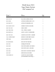
World Series 2001 Sega Naomi System Kit Contains List Part # Desc Qty 400-5397-01 NAOMI POWER SUPPLY 1 838-13616 AUDIO POWER AMP 2 CH 1 560-5407-UL AUDIO XFORMER 120V 1 838-13683-93CV1 JAMMA I/O BD (NAOMI) 1 600-7141-200 USB CABLE 1 600-7009-2500 VGA VIDEO CABLE 1 840-0051D-01 ASSY CASE PC1 DIMM BD 1 600-7247-500 CABLE SCSI TYPE 2 500MM 1 LOC.
ASSY CTRL PNL 2A4B2S MB2K2 ENG (NOA-20010-01) 2 (D-1/2)
ASSY CTRL PNL 2A4B2S MB2K2 ENG (NOA-20010-01) ITEM NO. (D-2/2) PART NO.
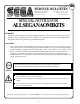
Feb 9. 2000 SERVICE BULLETIN SEGA Service Department 45133 Industrial Drive Fremont, Ca. 94538 120 http://www.seuservice.com Phone: 415.701.6580 Fax: 415.701.6594 SPECIAL NOTICE FOR ALLSEGANAOMIKITS PROBLEM: The SEGA Naomi Game kits are actually ‘JAMMA Dependent’. What this means exactly is they will only install into existing JAMMA Cabinets. If an operator tries to install these kits into a Non-JAMMA cabinet, they will first have to bring the wiring up to JAMMA Standards.
INSTALLATION INSTRUCTIONS 1) First. Remove all access panels from the game. Locate the original game Logic PCB’s & Power Supply and remove from the Cabinet by first disconnecting all harnesses from the boards. (You need only to splice in the Main Power (110v AC) into the 3-Pin Connector (GRN/WHT/BLK).) 2) Remove all existing game harnesses (we suggest using New Jamma Harnesses (NOT contained in the kit) to ensure reliability).
INSTALLATION INSTRUCTIONS 9) Proceed to place new decals on the sides of the cabinet. Locate a new monitor bezel, if needed, and replace glass, if required (due scratches). Install Instruction Placard to the back of the Monitor Glass. NOTE: As a precaution, disconnect the JAMMA Harness from the I/O Boards and turn power on. With a Multi-Meter, measure the 5v and 3.3v. Adjust if necessary to 5.15v DCand 3.3vDC. Measure the +12 to ensure the wires and voltages are in the correct position. Turn power off.
Sega Naomi System Switch Bracket and Speaker Installation Diagrams (Figure 3) To CN1 of Amplifier Board JAMMA Pin 8 Pin 1 Yellow Wire from Extra Harness (+5v) Pin 4 Pin 5 WHT/RED GRN/RED YEL/RED _ + Coin Meter Service Test JAMMA Pin JAMMA Pin JAMMA Pin Volume GRY/RED From CN2 of Amplifier Board From CN4 of Amplifier Board ORG/RED GRY/BLUE ORG/BLUE 7 R 1 15 Left Speaker Right Speaker
Sega Naomi System JAMMA Harness Wiring (JAMMA I/O BD) (Figure 4) Ground 1 A Ground Ground 2 B Ground +5v (Not Used) 3 C +5v (Not Used) +5v (Not Used) 4 D +5v (Not Used) (Not Used) 5 E (Not Used) +12v (Not Used) 6 F +12v (Not Used) Key 7 H Key Coin Meter 1 8 J Coin Meter 2 (Not Used) 9 K (Not Used) (Not Used) 10 L (Not Used) (Not Used) 11 M (Not Used) Video Red 12 N Video Green Video Blue 13 P Video Sync Video Ground 14 R Service Test 15 S (Not Used
Sega Naomi System Filter Board Information Connector Description etc. PSW2 PSW1 Service Switch DIPSW1 CN4 CN3 CN2 CN1 Test Switch Preamp Level Audio Out 1 2 3 VGA Level Video Out 4 Setting for High Resolution 31KHZ 1 -4 off 1 2 3 Setting for Standard Resolution 15KHZ 1 on 2-4 off.
1. SPECIFICATIONS Monitor Position 1 MONITOR Horizontal Synchronous Frequency 15/31 kHz HORIZONTAL 2 CONTROL PANEL NEW ASTRO CITY, NAOMI CABINET, NET CITY, BLAST CITY (PART NO.
Removing and Attaching the BAT MECHA If you need to remove the BAT MECHA as in the case of a failure, open the control panel base and remove the BAT MECHA through the following procedure. To reinstall the BAT MECHA, reverse the removing procedure, being certain that the BAT MECHA is faced in the correct direction. For instructions on opening the control panel base, refer to the Instruction Manual of the cabinet.
2. CONTENTS OF GAME • This is a sports action game where the Major League Baseball in the United States of America was taken as a subject matter. • In this game, the following teams appear: 14 American and 16 National teams, and two all-star teams from the two leagues. • The number of players appearing in the game is over 700. All of the 30 really existing ballparks also appear there. • The game player or players operate their favorite teams to participate in the baseball game, aiming at the win.
• The settings in GAME ASSIGNMENTS in the Test Mode control how the game ends: EXTRA INNING: If this is ON, the extra part of the baseball game continues to a maximum of 12th innings. If this is OFF, the baseball game ends when the bottom of the ninth inning ends (even if the score is even, i.e., the game is drawn). CALLED GAME: Can be set in the 5 to 10 range. When the difference in score reaches the setting, the baseball game ends (even if the bottom of that inning is not yet completed).
Pitching Gauge Batter's (Batting) Team 1P 123000080 RECORD 200378000 2P 8921000 Pitcher's (Fielding) Team ABC XYZ By operating the lever, move the batting cursor to aim at the ball. Select the course of the ball using the lever. While observing the pitching gauge, press the A Button timely (best when MAX appears at the top of the game). Release the batting switch timely to hit the ball.
Fielding Team Fielding Screen Landing Point 1P 123000080 OUT RECORD 200378000 2P 8921000 OUT Using the lever, move a fielder to the expected landing point of the ball. By pressing the B Button, you can replace the field you want to move. When approximating to the ball, the fielder automatically catches the ball. For example, the ball is occasionally carried away by wind. If you press the A Button timely, the fielder exhibits a super catch by fine play.
Pitch Type Marker The pitch type marker shows the available pitch types. FAST BALL FAST BALL SLIDER S C R E W SLIDER S C R E W BALL BALL SINKER CURVE SINKER CURVE CHANGE-UP FORKBALL ETC. CHANGE-UP FORKBALL ETC. For right-hander For left-hander Currently remaining ability Original ability of pitcher Batting Cursor If you successfully expect the actual pitch type, the shape of the batting cursor changes.
NAMES AND ABBREVIATIONS OF THE TEAMS AND BALLPARK NAMES APPEARING IN THE GAME The team names are listed alphabetically. American League National League 1. Anaheim Angels/ANA :Edison International Field 1. Arizona Diamondbacks/ARI :BankOne Ballpark 2. Baltimore Orioles/BAL :Oriole Park at Camden Yards 2. Atlanta Braves/ATL :Turner Field 3. Boston Red Sox/BOS :Fenway Park 3. Chicago Cubs/CHC :Wrigley Field 4. Chicago White Sox/CHW :Comiskey Park 4. Cincinnati Reds/CIN :Cinergy Field 5.
3. TEST MODE A. SYSTEM MENU STOP IMPORTANT When settings are changed in SYSTEM ASSIGNMENTS, COIN ASSIGNMENTS, and GAME ASSIGNMENTS of GAME TEST MODE, be sure to exit from the test mode of SYSTEM MENU screen. The contents of setting changes are stored in the IC on the BOARD when exiting from the Test Mode. If the power is turned off in the Test Mode (before exiting), the contents of setting changes are ineffective. In this case, the settings remain unchanged.
B. GAME TEST MODE By selecting "GAME TEST MODE" and pressing the TEST Button on the System Test Menu Screen, the Test Mode Menu Screen (Game Test Mode Menu Screen) appears, which is unique to this game. GAME TEST MENU INPUT TEST GAME ASSIGNMENTS VOLUME SETTING BOOKKEEPING BACKUP DATA CLEAR -> EXIT SELECT WITH SERVICE BUTTON AND PRESS TEST BUTTON GAME TEST MENU Screen • Pressing the SERVICE Button moves the arrow (->) on the screen. By moving the arrow, select the item you want to run.
a. INPUT TEST This test checks the input devices. Using this screen, check the input devices periodically. Pressing the TEST and SERVICE Buttons together returns you to the Game Test Menu Screen. INPUT TEST 1P_START :OFF 2P_START :OFF 1P_ABUTTON:OFF 2P_ABUTTON:OFF 1P_BBUTTON:OFF 2P_BBUTTON:OFF TEST-SW :OFF SERVICE-SW:OFF 1P_LEVER:(80,80) 2P_LEVER:(80,80) 1P_BAT : 80 2P_BAT : 80 PRESS TEST AND SERVICE BUTTON TO EXIT INPUT TEST Screen Operate each of the input devices.
b. GAME ASSIGNMENTS STOP IMPORTANT Once you have made change to the settings, select and run EXIT and exit the GAME TEST MODE. The new settings do not take effect until this mode is exited. This screen lets you make change to the game difficulty and other settings. Changing Procedure 1 Press the SERVICE Button to move the arrow to the item to which you want to make change. 2 Pressing the TEST Button changes the indication located at the right of the currently selected item. Change it to the desired one.
• DIFFICULTY: Set the difficulty by changing the pitching speed of the pitcher or modifying the CPU's routine of thinking. Set one of the following five levels: VERY EASY - EASY - NORMAL - HARD - VERY HARD Easier Harder • INNINGS: Set the number of innings you can play with the start-enabled (or continuable) credits. When each setting has been made, an additional credit is required each time any inning in parentheses (Å@) ends.
c. VOLUME SETTING STOP IMPORTANT Normal play is guaranteed only after all the input devices have been set up properly. Be sure to make the proper settings before you begin demonstration for the selling purpose. Once you have made change to the settings, select and run EXIT WITH SAVE and exit the GAME TEST MODE. The new settings do not take effect until this mode is exited. This screen lets you set the sensitivity of the input devices.
Setting Procedure 1 Move the lever and batting switch fully in the movable range. 2 Release the lever and batting switch, and leave them unloaded. Move Lever Horizontally (LEVER-H) Move the lever fully to the left or right, and then leave it unloaded. Move Lever Vertically (LEVER-V) Move the lever fully to the top or bottom, and then leave it unloaded. Batting Switch (BAT) Move the batting switch fully, and then leave it unloaded.
d. BOOKKEEPING This screen lists the data to be saved. Pressing the TEST Button returns you to the Game Test Menu Screen.
e. BACKUP DATA CLEAR BACKUP DATA CLEAR YES (CLEAR ) -> NO (CANCEL) SELECT WITH SERVICE BUTTON AND PRESS TEST BUTTON BACKUP DATA CLEAR Screen This screen is used to initialize BOOKKEEPING and the High Score Ranking. To clear the data about the coins/credits, you have to run BACKUP DATA CLEAR in the SYSTEM TEST MODE. Clearing the data does not influence any game settings (except the data). When clearing, use the SERVICE Button to bring the arrow (->) to "YES (CLEAR)" and press the TEST Button.
4. GAME BOARD Do not expose the Game Board so as to avoid causing an accident or malfunctioning. Static electricity discharge can damage electronic parts on the IC Board. Before starting work by opening the Shield Case Lid, be sure to touch grounded metallic surfaces to discharge physically charged static electricity. When replacing the Game Board, refer to the CVT Manual and Instruction Manual. 2 1 3 PART NO.
1 2 442-00067B (STICKER 840-0067B) Attached place 1 PART NO.
5. SOFT KIT STOP IMPORTANT Handling the GD-ROM Disk Do not contaminate the disks with your fingerprints or dust particles. Contaminated disks may lower audio and video quality. When cleaning the disks, do not use volatile chemicals (benzine, thinner, etc.), cleaning sprays, and antistatic agents. Do not use cracked, warped, or damaged Use clean cloth to wipe disks. the disk gently and into a radial direction. Do not attach papers or seals onto the disks; do not scratch the disks.
4 2 3 1 1 + 2 +3 +4 1 PART NO.
TRANSFORMER 50 838-13616 17V 0V 0V 17V 120V 560-5407 AUDIO POWER AMP 2CH JST VH 4P P C 1 2 3 4 5 6 31 50 50 41 51 50 5k pot 71 50 10 30 50 50 10 30 [Extra] [GD ROM DRIVE] 72 92 120 Vac Input 0V 80 91 1 2 3 WHITE(U/P) P C 3 1 Phono plugs 2 JST VL To Extra Yellow Wire 1 COIN COUNTER 6 838-13683-91 31 To PIN 8 of Jamma CN6 50 50 10 10 30 30 SW REGU FOR JVS GND GND P C 400-5397 +3.3V +5V GND GND GND +3.
VISIT OUR WEBSITE!