User's Guide Black-and-White Raster Plotter LP-1020 LP-1020L Read this User's Guide to use the plotter safely and properly. Keep this manual in a place where you can quickly access it at any time. Seiko I Infotech Inc. Downloaded From ManualsPrinter.
Downloaded From ManualsPrinter.
U00107742300 U00107742301 November 2007 December 2007 ©Seiko I Infotech 2007 Reprinting of this manual without permission is prohibited. The content of this manual may be changed without notice. D-SCAN is a registered trademark of Seiko Instruments, Inc. Ethernet is a registered trademark of Xerox, Inc. HP is a registered trademark of Hewlett-Packard (U.S.A.) MICRO CADAM is a trademark of CADAM, Inc. (U.S.A.) Athlon is a trademark of Advanced Micro Device, Inc.
CE Marking It is legally mandatory for products distributed or sold in the EU to bear a CE Mark that indicates compliance with requirements set forth in EC directives for the particular product. These directives set the scope of machinery subjected to the specific directive. Our LP-1020 complies with the EMC Directive (2004/108/EC) and Low Voltage Directive (2006/95/EC). For inquiries concerning CE Marks: Seiko Instruments Europe S.
Introduction Thank you for purchasing our LP-1020/1020L Black-and-White Raster Plotter (hereafter referred to as “this device”). This manual explains the overall device operations, functions and operation method under the premise that installation of the device has been completed. Before using this device, please read the “Safety Precautions” so that you may operate this device safely and correctly. Keep this manual in a place where you can quickly access it at any time.
Safety Precautions The following symbols are used in this manual to ensure the proper use of the plotter and to prevent the plotter from being damaged. Please follow these guidelines: WARNING Warnings must be followed carefully to avoid serious bodily injury or death. CAUTION Cautions must be observed to avoid damage to your equipment and bodily injury. Example of symbols: This symbol ( ) denotes items that require special care while executing a certain procedure or operation.
Warning DO NOT touch any of the parts inside the plotter with a "HIGH VOLTAGE" label attached as it may result in electric shock. DO NOT touch any of the parts inside the plotter with a "HIGH TEMPERATURE" label attached as it may result in severe burns. DO NOT disassemble or modify the plotter. DO NOT repair the plotter by yourself. Doing so may cause fire, electric shock or other accidents.
Caution DO NOT disassemble, modify the toner cartridge. If toner gets on your skin or clothes, wash off the affected area immediately with soap and water. Handle the toner cartridge with extreme care. Should any toner get into your eyes, do not rub them, flush them immediately with water, and see a physician immediately. Handle the paper rolls with care because they are very heavy. Dropping them may lead to personal injury. Use care when cutting the paper rolls with a scissors or knife during installation.
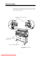
Warning labels Warning labels are affixed to this device at the locations indicated in the diagram below. You should understand the meanings of these warning labels and handling instructions. 3 “WARNING: HIGH VOLTAGE” label 2a “Caution when dealing with paper jam” label 1 “Caution: high temperature” label 2b “Caution when dealing with paper jam” label v Downloaded From ManualsPrinter.
1 “Caution: high temperature” label (It is affixed to the inside of the fixation door.) This label cautions you not touch this area due to high temperature. The fixation device will become hot. Take care to avoid contact when dealing with paper jams. 2 “Caution when dealing with paper jams” label This label indicates the direction that jammed paper should be pulled out when paper is jammed in the fixation device. Follow the directions on the label to remove the paper.
How to read this manual Manual make-up This manual is composed of 13 chapters and an appendix. Chapter 1 provides information that you should know before using this device, such as device features and part names. First read chapter 1 for an understanding of basic matters pertaining to this device. Chapter 2 provides information on matters you will need to know to operate this device, such as turning the power on and off, and how to put paper in the device.
Notation method Markings Warning ◆ This mark indicates warnings that must be followed carefully to avoid serious bodily injury or death. Caution ◆ This mark indicates cautions that must be observed to avoid damage to the equipment and bodily injury. Note ◆ Contain important information. This is a “Tip” mark. Contain additional hints for better use. ⇒ This is a “See” mark. A reference section and page is indicated after this mark.
Key/LCD/LED notations Indicates a control panel key. 1 2 3 Indicates the control panel LCD. Press to proceed to the menu screen where settings are managed. Press MENU # SETUP SETUP # POR T 1 _ H PG L and select “SETUP.” Press or and select “PORT2_HPGL.” SETUP # POR T 2 _ HPG L Indicates flashing light LED on, flashing, and off states are indicated as follows: On Flashing Off ix Downloaded From ManualsPrinter.
Supplied components Components and options listed below are included. If any components are missing or broken, contact your retailer or your nearest service center.
TABLE OF CONTENTS Introduction .......................................................................................... i Safety Precautions .............................................................................. ii Warning labels .................................................................................... v How to read this manual ................................................................... vii Manual make-up ...................................................................
Chapter 2 Basic operations 2-1 Plotting procedures overview ........................................................... 2-3 Turning the power on and off ........................................................... 2-3 Power on ............................................................................. 2-4 Power off ............................................................................. 2-6 Installation operations ......................................................................
Manual paper feeding (cut paper) .................................................. 2-34 Manual feeding procedures ............................................... 2-34 Manual paper feeding procedure ...................................... 2-35 Pause, continue, cancel (and additional printing) .......................... 2-39 Print stop ........................................................................... 2-39 Continue printing ...............................................................
Jobs ................................................................................................. 3-4 Reprinting ............................................................................ 3-4 Settings menu .................................................................................. 3-5 PDL menu ........................................................................................ 3-8 When using our company’s printer driver ............................ 3-8 Items which you can set .............
Chapter 5 "SETUP" Menu 5-1 Setting parameter items ................................................................... 5-2 Setup menu setting parameter table ................................... 5-3 Setup parameter priority mode .......................................... 5-10 PARAMETER MODE (DSCAN only) ................................. 5-11 MEDIA SERIES (HP-GL, TIFF, CALS only) ...................... 5-11 AUTO SUPPLY ................................................................. 5-12 FIXING MODE ......
Chapter 7 "PAPER" menu 7-1 Setting items .................................................................................... 7-2 MEDIA TYPE ....................................................................... 7-2 MEDIA SERIES ................................................................... 7-3 Chapter 8 "FUNCTION" menu 8-1 Setting items .................................................................................... 8-2 MENU PRINT .............................................................
Chapter 10 "RESET" menu 10-1 Reset functions .............................................................................. 10-2 SYSTEM RESET ............................................................... 10-2 PORT RESET ................................................................... 10-3 Chapter 11 "SYSTEM" menu 11-1 Setting items .................................................................................. 11-2 Communication parameter "COMM. PARAM" .................. 11-3 WEB LOCK .........
Chapter 13 Terioplot 13-1 About Terioplot .............................................................................. 13-2 Terioplot Hardware Requirements ................................................. 13-3 Settings .......................................................................................... 13-4 Restrictions .................................................................................... 13-5 Chapter 14 Troubleshooting 14-1 Troubleshooting ......................................
When a print error occurs ............................................................ 14-37 When there is an abnormal sound ............................................... 14-38 Appendix Appendix-1 Basic specifications ............................................................ Appendix-2 Plotter Specification ................................................ Appendix-2 Menu structure .................................................................... Appendix-4 [SETUP] MENU ...........................
Downloaded From ManualsPrinter.
Getting started Chapter 1 provides necessary information to operate this device. Read this chapter to understand the basics of this device before proceeding to the following chapters. Contents of this chapter Features Operating conditions The names and functions of each part How to read the status displays for this device 1-1 Downloaded From ManualsPrinter.
Features This device is an electrophotographic black-and-white raster plotter which produces plots by receiving graphic data created by a work station or PC (hereafter referred to as a computer.) This device is equipped with the following features: High speed plotting output, high resolution This device has 80 mm (3.15 inches)/sec recording speed and can output A0 size drawings at 3.4 sheets per minute. It can also output high accuracy drawings at 600 dpi resolution.
▼Features This device is equipped with a manual feeding print function. (Note) The picture quality and printing accuracy for manually fed printing cannot be assured. Multiport interface The device is equipped with an Ethernet interface and allows for network connection to network. It can also be equipped with both parallel interface and USB interface.
Operating conditions This section covers operating conditions of this device including environmental conditions, installation space, supported papers and spool memory configuration. Environmental conditions This device should be used within the temperature and humidity ranges indicated in the graph below. ◆ To obtain the best picture quality, use the device within a temperature and humidity range of 20 to 30°C, 45 to 60%RH.
▼Operating conditions Chapter 1 Before using this device Do not install the plotter in the following places: ◆ Places exposed to direct sunlight ◆ Places subject to vibration ◆ Places with excessive dust ◆ Places subject to extreme changes in temperature or humidity ◆ Places near an air conditioner or a heater ◆ Places where the plotter may get wet ◆ Places subject to direct air flow from a vent ◆ Places near a diazo copier that may generate ammonia gas ◆ Places with poor ventilation 1-5 Downloaded From
Installation space When installing this device, space to the front, rear, left and right sides of the device should be accommodated for the replacement of consumables, the processing of output drawings, and the ventilation. The minimum installation space indicated in the diagram below should be ensured. The maintenance space indicated in the diagram below is needed to perform parts replacement, etc. 700 (27.6) 1652 (65) 600 (23.6) 2052 (80.8) 1154 (45.4) 900 (35.5) 800 (31.5) 700 (27.6) 300 (11.
Supported Use roll paper specified by our company as indicated below: Note ◆If paper not specified by our company is used, picture quality cannot be assured. Moreover, the device may malfunction. ■Roll paper specified by our company Part No. Paper type & size LP-733 LP-780 LP-788 A0 size width (841 mm / 33.1 inches) Plain paper (67g / m2) A1 size width (594 mm / 23.4 inches) A2 size width (420 mm / 16.5 inches) LP-781 A3 size width (297 mm / 11.7 inches) LP-735 A0 size width (841 mm / 33.
The following roll paper of the widths can be also used. ■9×12 inch series Roll width Name of fixed form 36 inches (914.4 mm) 24 inches (609.6 mm) 18 inches (457.2 mm) 12 inches (304.8 mm) Lengthwise Widthwise E-form size 1219.2 mm (48 inches) 914.4 mm (36 inches) D-form size 914.4 mm (36 inches) 609.6 mm (24 inches) D-form size 914.4 mm (36 inches) 609.6 mm (24 inches) C-form size 609.6 mm (24 inches) 457.2 mm (18 inches) C-form size 609.6 mm (24 inches) 457.
▼Operating conditions Roll width Name of fixed form Lengthwise Widthwise 30 inches 30× 42 size form size (762.0 mm) 1066.8 mm (42 inches) 762.0 mm (30 inches) Roll width Name of fixed form Lengthwise Widthwise B1 form size 1000.0 mm (39.4 inches) 700.0 mm (27.6 inches) B2 form size 700.0 mm (27.6 inches) 500.0 mm (19.7 inches) B2 form size 700.0 mm (27.6 inches) 500.0 mm (19.7 inches) Lengthwise Widthwise B1 form size 1000.0 mm (39.4 inches) 707.0 mm (27.8 inches) B2 form size 707.
Paper storing precautions are as follows: Notes ◆Store the paper in a cool dark place with in the specified humidity ranges. ◆Store the paper in it’s packaging material so that dust will not accumulate on the paper. Spool memory configuration Spool memory configurations are available for this device as specified below. Expansion kit LP-815 Extends spool memory. Spool memory is the memory needed to receive plotting data.
This section explains the names, usage information, and functions of each part of this device. Front 1 Roll 1 drawer (door 1) Install paper roll. (⇒ page 2-11) 2 Roll 2 drawer (door 2) Install paper roll. (⇒ page 2-11) 3 Manual feed drawer (door 4) Open this drawer when a paper jam occurs during manual feeding. (⇒ page 14-3) 4 Finished drawing outlet Drawings exit from here. 5 Top cover (door 6) Open this cover when a paper jam occurs near the top door.
Right side/rear side 1 Main power switch Turns the device power on and off. (⇒ page 2-3) 2 Power cord Plug this cord into a power cord socket. 3 Parallel interface connector This is an interface connector conforming to the standards of the Parallel interface connector of Centronix. 4 Ethernet interface connector This is an interface connector for a 100 BASE-TX and 10 BASE-T Ethernet interface connector. 5 USB interface connector This is an interface connector for a USB 2.0 interface connector.
▼The names and functions of each part 1 Paper feed knob 2 Paper flange Chapter 1 Before using this device Interior Feeds the end of the roll to the paper feed inlet. (⇒ page 2-11) This flange is attached to the roll paper. (⇒ page 2-11) 1-13 Downloaded From ManualsPrinter.
Control panel The keys, LEDs and LCD are laid out on the control panel as illustrated in the following diagram. 2 LCD The status of this device, as well as a menu to set the device functions appears on a 20-digit, 2-line display. 1 LEDs The device status is indicated by LED’s on, flashing, and off. 4 Power key Use this key to turn ON/OFF this device. 3 Keys Use these keys to set device functions. 1-14 Downloaded From ManualsPrinter.
▼The names and functions of each part Number Name Error lamp (red) Function Indicates the presence or absence of errors. On: Error present Off: No error present Indicates the amount of remaining toner. On: There is sufficient toner. Toner lamp (green) Flashing: Toner is running low. Off: There is no toner (plots cannot be produced without replenishment.) LED’s Display Keys Power Waste toner lamp (green) Indicates the toner waste bottle replacement time.
How to read the status displays for this device This section explains the control panel LEDs and LCD which inform you of the status of the device. The following are the main displays. Data standby display Standard configuration PR I NT READY Error lamp Menu lamp This is a print ready status. Data processing display Indicates that data is being processed.
▼How to read the status displays for this device PR I NT F 0 1 HPGL 0 2 / 9 9✽S0 0 1 J009 Chapter 1 Before using this device Printing in progress display Error lamp Menu lamp Scheduled number of prints Number of prints executed Data is being printed. The various information for the data currently being printed is displayed. Print information display TOTA L TOTA L COUN T RUN ( m ) mmmmmm mmmmmm Error lamp Menu lamp is pressed in data standby or print ready status.
Warming up display WA RM I N G UP nnn Error lamp Menu lamp Counts down Displays the warming-up status and the time remaining until the device is ready. Power saving display P OW E R S A V I NG This display appears when the device enters the power saving mode after the data standby status has continued for a certain period of time. 1-18 Downloaded From ManualsPrinter.
Basic operations Chapter 2 describes basic operating procedures for this device such as turning the power on and off, replacing paper, and replacing toner will be explained.
Plotting procedures overview Plotting is usually conducted in accordance with the following procedures. For information on computer operations, refer to your computer manual. 1 Turn on the power for the computer and this device. For information on turning on the device power, refer to “Turning the power on/off” (⇒ page 2-3) 2 Confirm the status of the device on the control panel. Confirm that the LEDs are not indicating abnormalities and that the LCD indicates Data standby status.
Turning the power on and off Notes ◆While data is being processed, do not turn off the main power switch. Doing so may damage the system. ◆When the power is on and the Main power switch is turned off, or when the power goes out due to blackout etc., restoring the power (turning the Main power switch back on or resetting from a blackout) is the first step, but will not turn the plotter on. You must also turn ON the power key on the control panel.
Power on 1 Turn on the Main power switch located at the lower-left as seen from the rear of the device. Main power switch Press the power switch toward the ⎪ symbol (upwards). 2 Press the power key located on the control panel of this device (when the main power switch is on). I N I T I A L I Z I NG WA I T A MOM E N T When you first turn on the power after purchasing this device, a guidance display prompts you to set the panel's display language.
▼Turning the power on and off When a job is saved, the following message appears and the device stands by for selection. DE L E T E J OB ? Y=ENTER N=CANCE L If a key input is not made, this message will time-out after about 10 seconds and the device starts up with the job in saved condition. Under normal conditions, the display reads “INITIALIZING STANDBY” and is changed to the following message. S Y S T EM 01A V ERS I ON The message is changed to the “WARMING UP".
Power off When turning the power off, confirm that the device is in the data receive standby mode. 1 Press the Power key on the device panel for about 1 second. Release the key when the display reads "SHUTTING DOWN." When a job is present, it is automatically saved and will be printable the next time you turn the power on. (Only when HDD is installed) Note: Even when “SHUTTING DOWN” appears, the power will not turn off until you release the power key.
When you first turn on the power after purchasing this device, it will start up differently from how it will regularly start up thereafter. A guidance display will prompt panel display language selection, initializing of parameters appropriate for your region, and the setting of an IP address. By setting this IP address when the plotter is installed, you will be able to utilize the browser of a host computer on the same network as the plotter to make various settings.
■Turning on the power When a language has already been selected. I N I T I A L I Z I NG WA I T A MOM E N T L A NGUAGE ? ✽ E NG L I SH Select the language to be displayed on the panel using the , keys. L ANGU AGE ? ✽ ENG L I S H Press the L A NGUAGE ? ✽ E NG L I SH key to go to the confirmation screen. OK ? Press the key to choose this setting. I N I T I AL SET ✽S T ANDARD Select the optimal setup parameters according to your region using the , keys.
▼Installation operations Continued from the preceding page Press the Chapter 2 Basic operations U S I N G N E T WO R K ? Y = ENT ER N=CANCE L key. I P ADDRESS ? ✽000 . 000 . 000 . 000 D I S P L A Y I NG N E X T ? Y = ENT ER N= CANCE L Input the values using the keys. , , , , I P ADDRESS ? ✽ 1 9 2 .1 6 8 . 1 2 3 . 1 2 3 Press the screen. I P ADDRESS ? ✽ 1 9 2 .1 6 8 . 1 2 3 . 1 2 3 Press the key to go to the confirmation OK ? key to determine the selection.
Online and offline The device is “ONLINE” when it can receive and print data from the host computer and is “OFFLINE” when settings are being input on the control panel. You must set the device to “offline” to operate the menu from the control panel. Online To print from the host computer, the device must be online. Always make sure that the device is online to print from the host computer. If the device is not online, follow the procedures below to set the device online.
How to detach and reattach the paper rolls will be explained here. Detach and replace a paper roll when the device has run out of paper or when you change the paper roll size on type. When the paper is used up during printing, the Error lamp will turn on and the LCD will display the following message: Example: The screen requesting the A3 tracing paper to be loaded in the roll 1 drawer.
If an error message about paper supply appears on LCD, paper of larger size than required (or, if a type of paper is specified, paper of different type) can be chosen for printing. e.g. SET A 1 PAPER FORCE Press the key. Press the key. PR I NT ? PR I NT F 0 1 HPGL 0 1 / 0 1✽S0 0 1 J009 *Prints only when paper of larger size than required is available or if paper of a different type is available. *Alternative print is disabled, if printing on the manually fed paper.
▼Replacing paper rolls Precautions during replacement ◆The rolls are heavy so be careful not to hurt yourself by dropping them while you are replacing the rolls. ◆When attaching the rolls, use a cutter to cut the end of the paper roll. While doing this, take care not to cut yourself or damage the device. ◆When opening and closing the paper roll drawers, take care not to get your hands caught in the drawer. Do not open other paper roll drawers while one paper roll drawer is open.
How to detach the paper rolls 1 Pull out the Roll 1 or Roll 2 drawer. Use your fingers to grasp the handle in the center of the drawer and pull the drawer out gently. (The diagram indicates a case where the Roll 2 drawer is opened.) 2 Rewind the paper roll and then remove it. Turn the paper flange in the direction indicated in the diagram and continue to rewind the roll until you see the end of roll. Lift up the paper flange and remove the paper roll. Paper flange 2-14 Downloaded From ManualsPrinter.
▼Replacing paper rolls 3 Remove the paper flange and take out the paper roll. C L OS E O P E N Note Knob ◆Take care not to use excessive force when you turn the paper flange knobs. The flange ends may come off. 2-15 Downloaded From ManualsPrinter.com Manuals Chapter 2 Basic operations Loosen the paper flange by turning the knobs in the “OPEN” direction and remove both ends of the paper flange.
How to attach the paper roll ◆ The paper flange ends do not have a designated right or left side. You can attach them to either side. 1 Attach the paper flange to a paper roll. C L OS E O Note P E N Knob 2 Push in the paper flange ends until they contact the paper roll tube, then secure the flange ends by turning the knob in the “CLOSE” direction. ◆If the paper flange knobs are loosely fitted, the paper roll will move adversely to the right and left and negatively affect the drawing.
▼Replacing paper rolls Insert the end of the paper roll into the paper feed inlet of the device. Turn the paper flange and insert the end of the paper roll so that it is straight. Turn the paper feed knob so that the end of the paper roll projects about 10 cm. Paper feed knob 5 Cut the end of the paper. While holding the end of the paper roll, cut it off with the cutter. The “Paper cutter position” label is affixed to both ends of the space where the cutter blade should be inserted.
6 Close the paper roll drawer. Gently push in the Roll 1 or Roll 2 drawer. When the paper roll drawer is closed, the following message appears. WA I T A MOM E N T (It will take about 30 seconds until paper feeding is ready.) Note ◆After closing the paper roll drawer, wait until the “WAIT A MOMENT” message disappears before opening the paper roll drawer again.
Replacing the toner When there is no more toner availabe, the Toner lamp will go out, the Error lamp will come on, and printing will no longer be possible. The following message appears on the LCD. S E T TONE R CA R T R I DGE OPEN L EVER If the Toner lamp starts flashing or the ERROR message appears, replace the toner according to the procedures indicated below. ◆ When you open the toner door, you will find a “Toner replacement” label affixed to the inside surface. Refer to this when replacing toner.
Precautions on handling Warning Do not throw empty toner cartridges into fire. Doing so may cause accident and fire. Put the waste cartridge into the wrapping contained in the toner cartridge package and dispose of it as non-burnable garbage. Caution ◆Do not drop and tap the toner cartridge with force. Doing so may cause the toner to leak from the cartridge. ◆Do not directly touch the toner. If the toner gets on your skin or clothing, quickly wash it off with water.
▼Replacing the toner Toner replacement procedures ◆Toner should be replaced only when the device power is On. If the toner is replaced while the power is Off, the device will not be able to detect the amount of toner and an error status will not be cancelled even when toner has been replaced correctly. ◆Replace toner after plotting finishes. Replacing the toner during plotting may cause the operation to stop and the plotting data to be lost. 1 Open the toner cover.
4 Set the toner cartridge into the main unit. 5 Pull the lever to the right end. At this time, the following message appears on the LCD. After performing the procedure 6 operation, return the lever and remove the toner cartridge. C LOSE L EVER R E MO V E C A R T R I D G E If the above message does not appear, check to see that the lever has been pulled up to the right end. 2-22 Downloaded From ManualsPrinter.
▼Replacing the toner Tap the cartridge to allow toner to drop down. 7 Return the lever to the left. 8 Remove the toner cartridge and close the cover. Chapter 2 Basic operations 6 At this time, the following message appears on the LCD. WA I T A MOM E N T 2-23 Downloaded From ManualsPrinter.
Replacing the waste toner bottle When the waste bottle is nearly full with waste toner, the Waste toner lamp will flash. Although plots can continue to be produced for a little while longer, replace the waste bottle soon. When the waste bottle becomes full with waste toner, the Waste toner lamp will go out. The Error lamp will turn on and plotting will not be possible. The following message appears on the LCD.
▼Replacing the waste toner bottle ◆Do not drop and hit waste bottles containing waste toner. Doing so may cause toner to leak. ◆Take care not to directly contact the waste toner. If the toner gets on your skin or clothing, quickly wash it out with water. ◆Take care not to get the waste toner into your eyes or breathe it in. If waste toner gets into your eyes, wash your eyes out with plenty of water and consult a physician. Notes ◆Replace the waste bottle after plotting has been completed.
3 Remove the waste toner bottle from the main unit. 1 Lift up the waste bottle, 2 Remove it by pulling it out from the bottom end toward you. When you have removed the waste toner bottle, the LCD will display the following message. SET WA S T E 4 BOT T L E Attach the cap to the waste toner bottle. Cap Attach the cap which you have removed in procedure 1 to the waste bottle containing waste toner. Dispose of the waste bottle containing waste toner as non-burnable garbage.
▼Replacing the waste toner bottle Attach a new waste toner bottle. 1 Insert the mouth of the waste toner bottle onto the waste toner discharge port of the main unit by slightly lifting it. 2 Set it onto the bottom surface and position it so that it is stable. After the following message appears, the device status will return to the status before the waste bottle was replaced. WA I T 6 A MO M E N T Close the waste door. 2-27 Downloaded From ManualsPrinter.
Replacing the process cartridge When the Process cartridge approaches the end of its life, the Process lamp flashes and the following message appears. It is still possible to continue to produce plots in this condition, but you must replace the cartridge soon. PR I NT READY R E P L A C E PROC E S S Note ◆Above message may not appear in certain cases. If a new process cartridge is not installed soon, the Process lamp goes out, Error lamp comes on and plotting becomes impossible.
▼Replacing the process cartridge ◆Until you are ready to install the Process cartridge, do not unpack it and store it in its cardboard container. ◆Firmly hold the handles on both sides with both hands when handling the Process cartridge. ◆Take care not to scratch the surface of the photoconductor drum during handling. ◆With the exception of the handle area, take care to avoid contacting the surface of the photoconductor drum as much as possible.
2 Take out the Process cartridge. Pull the Process cartridge out by holding onto its handles. 3 Place a new Process cartridge on the top of the device. 1 Remove the Process cartridge from the box together with its protective case. 2 Place the Process cartridge on the top of the device together with the protective case. Two types of filters for replacement use are contained in the process cartridge packaging box. Replace the filter after replacing the process cartridge.
▼Replacing the process cartridge 4 Remove the orange tape. A sheet is attached to the tape at (2 points) on the inside. Remove the sheet together with the tape. 5 Remove the Process cartridge from its protective case. While holding onto the handles, open the protective case while pushing with your thumbs and remove the Process cartridge from the protective case. 2-31 Downloaded From ManualsPrinter.
6 Insert the Process cartridge. To insert the Process cartridge, align the Process cartridge with the angle of the open top cover and insert it in the direction of the alignment arrows (three points/green). After insertion, remove the protective cover from the top of the cartridge. 7 Close the top cover. 8 Remove the filter cover. Pull out the filter covers at 2 points on the right side of the main unit as it faces you, and remove them. 2-32 Downloaded From ManualsPrinter.
▼Replacing the process cartridge Replace the filter. Pull out the filters toward you and remove, and replace with the two filters contained in the process cartridge packaging box. 10 Attach the filter covers and turn ON the device. 2-33 Downloaded From ManualsPrinter.
Manual paper feeding (cut paper) This device offers a manual feeding feature as a service function. As this is a service function, we cannot assure the picture quality and printing accuracy. Manual feeding procedures 1 Adjust the paper guide. Adjust the paper guide to the position where you will set the cut paper for manual feeding. 2 Set the paper so that the printing surface is face down.
▼Manual paper feeding (cut paper) 1 Set the paper feeding mode. When the PDL setup paper feeding mode is set to the continuous or optimum mode, paper should be manually fed only for the drawings for which the data was processed immediately after the paper was fed into the manual paper feeding unit (this function is called "interrupt manual feeding function".) When the PDL setup paper feeding mode is the manual feeding mode, paper should be always fed from the manual paper feeding unit.
9× 12 series fixed form cut paper Name of fixed form Lengthwise length Widthwise length E 1219.2 mm (48 inches) 914.4 mm (36 inches) D 914.4 mm (36 inches) 609.6 mm (24 inches) C 609.6 mm (24 inches) 457.2 mm (18 inches) B 457.2 mm (18 inches) 304.8 mm (12 inches) A 304.8 mm (12 inches) 228.6 mm (9 inches) 9× 12 series width cut paper Width name Paper width E width 914.4 mm (36 inches) D width 609.6 mm (24 inches) C width 457.2 mm (18 inches) B width 304.
▼Manual paper feeding (cut paper) Name of fixed form Lengthwise length Widthwise length B1 1000.0 mm (39.4 inches) 700.0 mm (27.6 inches) B2 700.0 mm (27.6 inches) 500.0 mm (19.7 inches) Map series width cut paper Width name Paper width B1 width 700.0 mm (27.6 inches) B2 width 500.0 mm (19.7 inches) Paper length Max. up to printing length DIN series fixed form cut paper Name of fixed form Lengthwise length Widthwise length B1 1000.0 mm (39.4 inches) 707.0 mm (27.8 inches) B2 707.
When feeding the cut paper into the manual paper feed inlet, follow the procedure below (position the cut paper in the center of the manual paper feed inlet). When plotting on the fixed form paper, set the paper as shown below (the paper input direction varies depending on the fixed form paper size). Set the paper (sideways) in case of: A4 fixed form cut paper of A series A fixed form cut paper of 9×12 series B3 fixed form cut paper of DIN series A fixed form cut paper of 8.
Pressing the key during printing takes the device offline and allows you to temporarily stop printing by pressing the key. Pressing the key during printing gives you the option to cancel the drawing being printed. Pressing the key during Print stop status allows the device to be returned to Online status and to continue printing. Print stop Press the key during printing and set the device to Print stop status.
Cancel printing Press the key during printing and the following Cancel message will appear. After a Print cancel is processed, the display will return to the Online display. CANCE L PR I NT ? F 0 1 HPGL Press the PR I NT J009 key. READY Additional printing In the data standby condition, the same drawing as that printed last (called "accumulated drawing") can be additionally printed. At this time, the number of copies can be also specified. PR I NT Press the READY key. No.
Through your Web browser, you can use the following functions remotely from a host computer. In order to use these functions, it is necessary to have the device IP address preset. Moreover, it is necessary to have the browser set to enable Cookies and JavaScript. For information on the setting method, refer to the Help menu for your host computer’s browser (or OS). Functions (1) Device status display function This function allows you to check the status of the device etc. from the host display screen.
Web function startup method 1 The following preparations must be made from the plotter side. 1 Turn on the plotter power. 2 Confirm the IP address setting. (If this setting has not yet been set, set this setting according to the instructions which appears when the device is booted). 3 Set each Ethernet parameter where necessary. 2 Launch the Web browser. 1 Obtain the Web browser for the host computer. • Microsoft Internet Explorer Ver11.5 and later • Netscape Communicator Ver5.
Cleaning the exterior To clean the exterior of the device, soak a soft cloth with water or a neutral detergent, and wring the cloth well and wipe away dirt. ◆Never use a volatile solvent such as a thinner, benzine, and alcohol. 2-43 Downloaded From ManualsPrinter.
Using paper of new standard series This device supports the following series of paper. A series 9×12 inch series 8.5×11 inch series 30×42 inch series Map series DIN series Chinese series The device is set up when shipped out of the factory so as to support the A series or A and Chinese series. You can check for which series your device is currently set up for by the enable series (page 11-5) (any series having been set to ON can be used). The steps to add new series are added is described below. The 8.
▼Using paper of new standard series Note (3) Place the roll in the drawer Load the roll of the 8.5×11 inch series to be used into the roll paper drawer. See page 2-16 for instructions on loading the paper roll. When using the cut paper of the 8.5×11 inch series, this step is not needed. (4) Setting the paper menu Set the media series of the drawer into which the roll of the 8.5×11 inch series was set to the 8.5” series (page 7-2). When using the cut paper of the 8.
Using paper of Chinese standard series Rolls of the China series listed below can also be used with this device. Plotting of the fixed form cannot be performed with the roll of the China series. All the plots produced in this mode are in the actual length. China A0 roll width China A1 roll width China A2 roll width China A3 roll width 914 mm (36 inches) 620 mm (24.4 inches) 450 mm (17.7 inches) 310 mm (12.2 inches) 910 mm (35.8 inches) 610 mm (24 inches) 440 mm (17.3 inches) 297 mm (11.
▼Using paper of Chinese standard series Note ◆All of the rolls of the China series cannot be set to OFF at the same time. ◆If this setting is changed, the device must be restarted. (4) Place the roll in the drawer Place the roll of the China series to be used in the drawer. Refer to the page 2-15 for instructions on replacing the paper roll. When using the cut paper of the China series only, this step is not needed.
Limiting rolls to be used When limiting rolls to be used for operation to A0 and A1 rolls, for example, the following process is recommended. (1) Setting the apply roll Set the rolls to be used to ON in the apply roll setting process (page 11-6). Set the rolls not used to OFF.
Chapter 3 Chapter 3 provides an overview of the menu functions covered by this device. Contents of this chapter Channels and ports Data format Job Setting menu PDL menu Items which you can set Menu screen 3-1 Downloaded From ManualsPrinter.
Channels and ports This device is equipped with standard Ethernet interface connectors. The Ethernet interface has 10 logical ports. Moreover, the device is capable of parallel and USB interface connection when the device has been equipped with these 2 types of interface. This allows the device to receive data from up to 12 computers simultaneously.
Data formats Data formats which can be used This device supports the data formats indicated below. ■Data formats Data formats DSCAN This is our company's original D-SCAN format. It also supports D-SCAN Raster data. HPGL Supports our company's D-SCAN C/C2 format. (hereafter referred to as HP-GL format.) TIFF A data format conforming to TIFF Revision 4.0 CALS A data format conforming to CALS Raster Type I.
Jobs The device manages the received data in units of “jobs.” Data transferred in units of “FILES” and data managed by the device in units of “JOBS” refer to the same thing. However, as data comprised of multiple drawings can also managed as a single job. So one print job isn’t mecessarily composed of one drawing. For all print fobs, the print status of the job can be checked from the remote control, the print order can be changed, and reprinting etc. is available.
Settings menu 1 2 3 4 Setup menu System menu Protocol menu Device menu Sets printing parameters etc. Sets system settings for the entire device. Sets communication protocol settings. Sets operating status settings for the device engine. Moreover, this device has four Print parameter setup tables to be used independently for each of the parallel channels and Ethernet ports. These tables can be set from the Setup menu (this Setup table is referred to as the PDL table hereafter).
(1) Setup menu Change the settings for each PDL in Setup menu listed below: Menu name Setup —— PORT n—HPGL —— PORT n—DSCAN —— PORT n—TIFF —— PORT n—CALS : —— PARA—CALS —— USB—HPGL Note: Disabled ports will not be indicated (refer to Port select in the System menu). Only the PDL selected via PDL Select is displayed (refer to PDL Select in the Protocol menu). Parallel and USB will only be indicated when each interface is installed. USB will only indicate HPGL. 3-6 Downloaded From ManualsPrinter.
▼Setting menu (2) Protocol menu For each parallel channel and port in the Protocol menu, select the PDL numbers in “PDL SELECT” as listed below. When the Protocol menu is changed, system reset is executed.
PDL menu The various print parameters can be set in the PDL table from the Panel setup menu. The PDL processing program performs print processing in accordance with the print parameter settings. Setting each print parameter allows for convenient operation by allowing you to change how paper is fed and delivered, and enables you to reduce the scale of a drawing.
Items which you can set Chapter 3 Menu overview Set the device offline before performing setting operations. When you press to set the device offline, the following message appears on the display. Changed parameters are saved in non-volatile memory and are not lost when the power is turned off. Although the offline display appears even while printing, there are functions which cannot be operated and these menus will not be displayed.
Printing status MENU # SETUP MENU #DEV I CE MENU # PAPER MENU # PRO T OCO L MENU #RESET MENU # S Y S T EM 3-10 Downloaded From ManualsPrinter.
Menu screen When the device is online and you press the screen appears. Select a menu using the , key to enter each menu. key to go offline, a menu keys and press the Press the key on the display indicated below to enter the Setup menu. MENU # SETUP Press the key SETUP # POR T 1 _ H PG L Perform PDL parameter settings. For PDL parameter settings, set printing mode etc. The Setup menu also contains the following items.
Device menu “DEVICE” From the display indicated below, press the menu. key to enter the Device MENU #DEV I CE Press the # P OW E R > 1 5m i n Menu Item key. SAVE Functions POWER SAVE Sets the time until the device enters the power saving mode. EDGE CUT TIMER Sets the data standby time to automatically have the paper roll end cut before plotting using data received after a Data standby status has continued for a while.
▼Menu screen Paper menu “PAPER” Press the menu. key while the display below is appearing to enter the Paper Press the Chapter 3 Menu overview MENU # PAPER key. PAPER # RO L L 1 In this menu, you can specify the paper type and series. 3-13 Downloaded From ManualsPrinter.
Function menu “FUNCTION” Press the key on the display below to enter the Function menu. MENU # F UNC T I ON Press the key. #MENU PR I N T > S Y S T EM Menu Item Function MENU PRINT Prints the status of consumables, device information, and panel settings. HPGL SELF PLOT Outputs the drawing for the data format (HPGL) built in this device. DSCAN SELF PLOT Outputs the drawing for the data format (DSCAN) built in this device. ERROR LOG Prints error log information.
▼Menu screen Protocol menu “PROTOCOL” Press the key on the display below to enter the Protocol menu. MENU # PRO T OCO L key. Chapter 3 Menu overview Press the P RO T OCO L # POR T 1 : X P T After changing these settings, the system will reset. Menu Item Function PORTn : xxx The Ethernet port PDL selection and protocol name are set here. N indicates the port number, xxx indicates the Ethernet protocol type. Up to 10 ports may be specified.
Reset menu “RESET” Press the key on the display below to enter the Reset menu. MENU #RESET Press the # S Y S T EM > Menu Reset Item key. RESET Function SYSTEM RESET System reset Initializes the device to the same status as when the device power is turned on. PORT RESET Ethernet port reset Resets the communication for the selected logical port. 3-16 Downloaded From ManualsPrinter.
▼Menu screen System menu “SYSTEM” Press the key on the display below to enter the System menu. Press the Chapter 3 Menu overview MENU # S Y S T EM key. S Y S T EM # C O MM . P A R A M The system will be reset after these changes are made. Menu System Item Function COMM. PARAM Sets the communication parameters. WEB LOCK Sets whether to allow setup privileges from the web browser to User administrator and above. ENABLE SERIES Sets the media series to be used in this device.
Downloaded From ManualsPrinter.
Chapter 4 Chapter 4 provides the basic operating information that you set up each menu. Contents of this chapter Summary of basic menu operation Offline menu operation 4-1 Downloaded From ManualsPrinter.
Summary of basic menu operation To enter each menu, operate the respective keys as shown below: MENU # SETUP SETUP # POR T 1 _ H PG L Setup menu MENU #DEV I CE # P OW E R > H I GH SAVE EF C T Device menu MENU # PAPER PAPER # RO L L 1 Paper menu MENU # F UNC T I ON #MENU PR I N T > S Y S T EM Function menu MENU # PRO T OCO L P RO T OCO L # POR T 1 : X P T Protocol menu MENU #RESET # S Y S T EM > RESET Reset menu MENU # S Y S T EM S Y S T EM # C OMM .
Offline menu operation Press the key to enter the offline mode. If data remains, some menus may not be displayed though key operation is available. Select the menu group using the To enter each menu, press the and keys. key. Switching the menu on the same hierarchy Press the or key to switch the menu within the same hierarchy.
Moving the menu hierarchy You can move through the menu hierarchy using the An example of the setup menu group is shown below: SETUP # POR T 1 _ H PG L 4-4 Downloaded From ManualsPrinter.com Manuals AUTO SUPP L Y > C O N T MO D E or key.
▼Offline menu operation Setting or changing the parameters Press the key to change the parameters. Press the or key to select a parameter. Shift the digits of a numerical value or character to enter a desired one using the and keys. Press the key to select the parameter. Use the key is used to execute the respective functions. Chapter 4 Basic Menu Operation In some menus, the key to cancel the parameter entered.
■Numerical value input method Shift the digits of a numerical value to enter a desired value using the and 1 keys. Press the key to get ready for input. # I P ADDRESS ✽020 . 005 . 070 . 2 100 Shift the numeral value digits using the key (or key). # I P ADDRESS ✽020 . 005 . 070 . 3 100 Change the numerical value using the key (or key). # I P ADDRESS ✽010 . 005 . 070 . 4 100 Change the parameter using the , keys. # I P ADDRESS ✽010 . 005 . 067 .
▼Offline menu operation ■Character input method Shift the digits of the characters using 1 Press the and keys. key to get ready for input. # US ER NAME ✽FTP03 Shift the characters, digits using the key (or key). # US ER NAME ✽FTP03 3 Change the characters using the key (or key). # US ER NAME ✽FSP0 3 4 Change the parameter using the , , and keys. # US ER NAME ✽USER1 5 Select the new characters using the key. # US ER NAME >USER1 Press the key to cancel the change.
■Execution method # ENG I NE > 1 Press the key to get ready for input # ENG I NE ✽ 2 L OG L OG Execute using the OK ? key (or return to exit display without execution using the L OC A L PR I NT key). 01 / 01 After completion of execution, display before the execution appears. 4-8 Downloaded From ManualsPrinter.
▼Offline menu operation ■Choice execution method #MENU PR I N T > S Y S T EM Press the key to get ready for input. #MENU PR I N T ✽ S Y S T EM 2 OK ? Select a parameter using the #MENU PR I N T ✽ POR T 1 3 Execute using the PR I NT key). OK ? key (or return to exit display without execution using the L OCA L key (or key). 01 / 01 After completing execution, display before execution appears. 4-9 Downloaded From ManualsPrinter.
Exiting the setting Press the 4-10 Downloaded From ManualsPrinter.com Manuals key to return to the online condition.
▼Setting parameter Items Chapter 5 "SETUP" Menu Chapter 5 explains how to set the print parameters. Contents of this chapter Chapter 5 "SETUP" Menu Setting parameter items 5-1 Downloaded From ManualsPrinter.
Setting parameter items The following print parameters can be set. SET UP # POR T 1 _ HPG L Setting PDL parameters and device parameters can be set. • • • • • • • • • • • PARAMETER MODE (DSCAN only) MEDIA SERIES (8HP-GL, TIFF, CALS only) AUTO SUPPLY FIXSIZE MODE COPY COUNT SUPPLY PARAM. DRAWING PARAM. SCALING PARAM. FORMAT PARAM.(HP-GL, DSCAN only) PEN PARAMETER (HP-GL, DSCAN only) RASTER PARAM.
▼Setting parameter items Setup menu setting parameter table Menu First hierarchy item Second hierarchy item SETUP #PORT n_HPGL SETUP #PORT n_DSCAN SETUP #PORT n_TIFF Refer to (A) Note 1) SETUP #PORT n_CALS SETUP #PARA_HPGL SETUP #PARA_DSCAN SETUP #PARA_TIFF Refer to (A) SETUP #PARA_CALS SETUP #USB_HPGL Note 1) Disabled ports will not be indicated. (refer to PORT select in the system menu.) Only the PDL selected via PDL select is displayed. (refer to PDL select in the Protocol menu.
(A) Second hierarchy item Third hierarchy item name Parameter Remarks - DATA FIRST, PANEL FIRST DSCAN only - A SERIES 9" SERIES 8.5" SERIES 30× 42 SERIES MAP SERIES DIN SERIES CHINA SERIES HP-GL, TIFF, CALS only - CONT MODE OPTIMAL MODE ROLL 1 MODE ROLL 2 MODE MANUAL FEED FIXSIZE MODE - FIXED SIZE EXTENSION A FIXED SIZE REAL SCALE COPY COUNT - 1 to 99 (Initial value=1) PARAMETER MODE MEDIA SERIES AUTO SUPPLY DSCAN displays the FIXED SIZE as A FIXED SIZE. SUPPLY PARAM.
▼Setting parameter items (C) Parameter Remarks OFFSET MODE MARGIN VARIABLE SIZE FIXED SIZE MARGIN (mm) 0 to 100 (Initial value=0) MARGIN (in) 0 to 3.9 inches (Initial value=0) X-OFFSET (mm) -9999.99 to +9999.99 (Initial value=0) X-OFFSET (in) -393.700 to +393.700 inches (Initial value=0) Y-OFFSET (mm) -9999.99 to +9999.99 (Initial value=0) Y-OFFSET (in) -393.700 to +393.
(D-1) Fourth hierarchy item Parameter Remarks A4 A4 A3 A2 A1 A0 Enabled when scale mode = manual scale. A3 A3 A2 A1 A0 A4 Enabled when scale mode = manual scale. A2 A2 A1 A0 A4 A3 Enabled when scale mode = manual scale. A1 A1 A0 A4 A3 A2 Enabled when scale mode = manual scale. A0 A0 A4 A3 A2 A1 Enabled when scale mode = manual scale. (D-2) Fourth hierarchy item Parameter Remarks A A B C D E Enabled when scale mode = manual scale. B B C D E A Enabled when scale mode = manual scale.
▼Setting parameter items (D-3) Parameter Remarks A A B C D E Enabled when scale mode = manual scale. B B C D E A Enabled when scale mode = manual scale. C C D E A B Enabled when scale mode = manual scale. D D E A B C Enabled when scale mode = manual scale. E E A B C D Enabled when scale mode = manual scale. Chapter 5 "SETUP" Menu Fourth hierarchy item 5-7 Downloaded From ManualsPrinter.
(E) Third hierarchy item Parameter Remarks ENABLE DISABLE CHINA HP-GL only GRAPHIC LANG. AUTO HP-GL HP-GL/2 HP-GL only TERMINATOR PG1; ON OFF HP-GL only TERMINATOR NR; ON OFF HP-GL only TERMINATOR SP0; ON OFF HP-GL only TERMINATOR ESC.) ON OFF HP-GL only TERMINATOR AF; ON OFF HP-GL only TERMINATOR AH; ON OFF HP-GL only TERMINATOR FR; ON OFF HP-GL only PLAN SIZE ON (PS) ON (IP) ON (IW) OFF HP-GL only DRAWING NOP EOP DSCAN only PAPER NO.
▼Setting parameter items (F) Parameter Remarks PEN PAR. MODE DATA PRIORITY PANEL PRIORITY PEN N WIDTH (mm) 0.00 to 16.00 (Initial value) PEN 0 : 0.2 PEN 1 : 0.3 PEN 2 : 0.4 PEN 3 : 0.5 PEN 4 : 0.6 PEN 5 : 0.7 PEN 6 : 0.8 PEN 7 : 0.9 PEN 8 and later : 1.0 Pen 8 and later: 10 Set HP-GL to pen 0 to 15. 0.00 is 1-dot width. Set DSCAN to pen 1 to 32. PEN N WIDTH (in) 0 to 0.629 inches (Initial value) PEN 0 : 0.008 inches PEN 1 : 0.012 inches PEN 2 : 0.016 inches PEN 3 : 0.020 inches PEN 4 : 0.
(G) Third hierarchy item Parameter IMAGE SCALE LINE DRAW. MODE PICTURE MODE SCREENING LINE DRAW. MODE GRAPHICS MODE PICTURE MODE Remarks HP-GL, DSCAN, TIFF only Setup parameter priority mode HP-GL PDL and D-SCAN PDL allow for selecting the setup parameter priority mode (DATA FIRST/PANEL FIRST). Even if the DATA FIRST mode is specified, the settings preset in this printer are used for the parameters to which no data has been specified.
▼Setting parameter items PARAMETER MODE (DSCAN only) Allows for determining which setting is enabled for parameters which can be set both with data or on the panel. This setting is performed on the second hierarchy. Note ◆ The DSCAN format is for only customers in Japan. MEDIA SERIES (HP-GL, TIFF, CALS only) When the paper feed mode is set to CONT MODE, OPTIMAL MODE, or MANUAL FEED mode, set the series of paper to be fed. This setting is performed on the second hierarchy.
AUTO SUPPLY Allows for setting the paper feeding conditions. This setting is performed on the second hierarchy. CONT MODE OPTIMAL MODE ROLL 1 MODE ROLL 2 MODE MANUAL FEED : Default value When plots can be produced without clipping the drawing, the plots are continuously produced (Small rolls only). An optimum roll is used for plotting to minimize wasted media. If the optimum roll is not loaded, the printing process is suspended and replacement of paper is demanded.
▼Setting parameter items FIXING MODE A series Long side Short side A0 size 1189.0 mm (46.8 inches) 841.0 mm (33.1 inches) A1 size 841.0 mm (33.1 inches) 594.5 mm (23.4 inches) A2 size 594.5 mm (23.4 inches) 420.5 mm (16.6 inches) A3 size 420.5 mm (16.6 inches) 297.3 mm (11.7 inches) A4 size 297.3 mm (11.7 inches) 210.3 mm (8.3 inches) 9× × 12 series Long side Short side E size 1219.2 mm (48 inches) 914.4 mm (36 inches) D size 914.4 mm (36 inches) 609.
: Default value* FIX SIZE Produces fixed form of plots. EXTENSION A In addition to the fixed size of A1 to A4, sizes extended from the fixed size by 0.5 in vertical direction (1.5A3, 2A2, etc.) are also handled as the fixed form. When plotting on paper other than the A series, use the fixed form plotting procedure. REAL SCALE Prints at actual length. Notes ◆ The default value varies depending on the setting in the INITIAL SETTING.
▼Setting parameter items SUPPLY PARAM. ■CENTERING Aligns a drawing to the center of the paper. (See the figure below.) This setting is found on the third hierarchy. Centering ON Centering OFF Chapter 5 "SETUP" Menu OFF ON : Default value Centering is not performed. Centering is performed. For the data which cannot be completely saved in the spool memory, centering is not available.
■SIZE MARGIN (mm) / SIZE MARGIN (in) Allows for setting of the margin to be used or extended fixed form paper is used when these settings also apply a plot is produced on paper size in the actual length. The paper size of the fixed size or paper roll size is judged as being larger by the value preset for the size margin. However, the area where plotting can be performed actually is the original paper size, and thus the drawing area beyond the original paper size is clipped.
▼Setting parameter items DRAWING PARAM. This is a parameter group that you need to set plotting conditions. ■OFFSET MODE Allows for setting which offset function is used from among MARGIN/ VARIABLE SIZE OFFSET/FIXED SIZE OFFSET. This setting is performed on the third hierarchy. MARGIN VARIABLE SIZE FIXED SIZE : Default value MARGIN is used as the offset function. Setting of MARGIN is enabled. Offset X and Y are used as the offset function. Offset X and Y setting is enabled.
■MARGIN (mm) / MARGIN (in) Allows for setting of the margin size to be added to the circumference of drawing actual length. This setting is enabled at the time of OFFSET MODE = MARGIN setting. This setting is performed on the third hierarchy. 0 to 100 (0 to 3.9 inches) Default value = 0 a a Drawing Drawing Y Y a X X Paper feed direction Cut position Paper feed direction Cut position a.
▼Setting parameter Items ■WRITE MODE Allows for setting of the drawing overlap method. When the HP-GL data is used for setting the WRITE MODE, the data setting is enabled. The default setting is "OR WRITING". This setting is changed on the third hierarchy. ■MIRROR Allows for setting whether to produce a plot by turning over the plot around the drawing center line in parallel with the X axis (line symmetry). This setting is performed on the third hierarchy.
■REVERSE (TIFF, CALS only) Allows for setting whether reverse plotting (with black and white inverted) is made or not. This setting is performed on the third hierarchy. : Default value OFF Reverse plotting is not performed. ON Reverse plotting is performed. ■ERROR MEMO Allows for setting whether to attach an error memo beside the plotting if a command error or other PDL error occurs. This setting is performed on the third hierarchy.
▼Setting parameter items SCALING PARAM. This is a parameter group that allows you to set scale conditions. ■SCALE MODE : Default value MANUAL SCALE Automatic scaling does not take place. Manual scale parameters (scale X and Y and fix scale) are enabled. REDUCE Drawing is automatically reduced to be within the paper size. Automatic reduction Drawing Drawing Y X Paper feed direction 5-21 Downloaded From ManualsPrinter.
■SCALE X (%) SCALE Y (%) When setting "SCALE MODE = MANUAL SCALE," values of the scale applied to X and Y directions of the drawing are set up. This setting is performed on the third hierarchy. 0.01 to 1000.00 Default value = 100 This setting is enabled when setting "SCALE MODE = MANUAL SCALE." When it is set to 100%, the plot is produced in 1-to-1 magnification.
▼Setting parameter items FIX SCALE A Automatically scaled to A4 fix size. Automatically scaled to A3 fix size. Automatically scaled to A2 fix size. Automatically scaled to A1 fix size. Automatically scaled to A0 fix size. Chapter 5 "SETUP" Menu FIX SCALE 9" A Automatically scaled to 9×12 inch series A fix size. B Automatically scaled to 9×12 inch series B fix size. C Automatically scaled to 9×12 inch series C fix size.
FORMAT PARAM. (HP-GL DSCAN only) These are parameters that you need to set the HP-GL format and DSCAN format analysis conditions. ■PRT DRIVER (HP-GL only) Allows for choosing whether or not to use the printer driver. When the printer driver is operated together with another driver, this setting should be ENABLE. Even when the printer driver for LP-1020 is set to the PANEL FIRST mode, this setting can be set to ENABLE without causing a problem. This setting is performed on the third hierarchy.
▼Setting parameter items ■GRAPHIC LANG. (HP-GL only) : Default value AUTO Judges HP-GL or HP-GL/2 automatically. HP-GL/2 Judges the data received as HOP-GL/2. HP-GL Judges the data received as HP-GL. When HP-GL is employed, the origin of coordinates should be the center point. When HP-GL/2 is employed, the origin of coordinates should be the left lower point. When HP-GL is employed, HP-GL/2 data can be received without causing an error.
■PLAN SIZE (HP-GL only) Sets which command is to be enabled as a drawing size command. Sets data to OFF if the drawing size is not properly set. This setting is performed on the third hierarchy. : Default value ON (PS) Sets the PS command as the drawing size. ON (IP) Sets the IP command as the drawing size. ON (IW) Sets the IW command as the drawing size. OFF Disables the drawing size command.
▼Setting parameter items ■DRAWING (DSCAN only) Sets whether or not to plot DRAWING. This setting is performed on the third hierarchy. : Default value NOP DRAWING Plot is not performed. EOF DRAWING Plot is performed. Allows for setting how to handle the paper type No. When handling the paper type No. as the paper source, paper supply is controlled as listed below. This setting is performed on the third hierarchy.
Manual feed + two-step roll model Paper type No. Paper supply control 0 Sets paper type No. = disable. Supplies paper according to the panel paper supply mode setting. 1 Controls paper supply in the paper supply mode = roll 1 mode. 2 Controls paper supply in the paper supply mode = roll 2 mode. 3 Controls paper supply in the paper supply mode = manual feed mode. 4 and above Controls paper supply in the paper supply mode = roll 1 mode. When handling paper type No.
▼Setting parameter items PEN PARAMETER (HP-GL DSCAN only) Allows for setting of the thickness (line width), density and other plotting conditions for the pen of this device. The number of pens is different in HP-GL and DSCAN. HP-GL: 00 to 15 DSCAN: 01 to 32 ■PEN PAR. MODE : Default value DATA PRIORITY Pen attributes enable DATA setting. PANEL PRIORITY Pen attributes enable PANEL setting.
Specified value (mm (inch)) No. of dots Specified value (mm (inch)) No. of dots 0.00 to 0.06 (0.00 to 0.0024) 1 0.53 to 0.57 (0.0209 to 0.0224) 13 0.07 to 0.10 (0.0028 to 0.0039) 2 0.58 to 0.61 (0.0228 to 0.024) 14 0.11 to 0.14 (0.0043 to 0.0055) 3 0.62 to 0.65 (0.0244 to 0.0256) 15 0.15 to 0.19 (0.0059 to 0.0075) 4 0.66 to 0.69 (0.026 to 0.0272) 16 0.20 to 0.23 (0.0079 to 0.0091) 5 0.70 to 0.74 (0.0276 to 0.0291) 17 0.24 to 0.27 (0.0094 to 0.0106) 6 0.75 to 0.78 (0.0295 to 0.
▼Setting parameter items ■PEN N CORNER Allows for setting of the line end shape of the pen of this device. This setting is performed on the third hierarchy. : Default value ROUND Specifies the line end in a round shape. BUTT Specifies the line end in a butt shape. • Line end shape of each parameter is illustrated below. BUTT a a = 1/2 of line width • Any combinations other than CORNER = "ROUND" and JOINT = "ROUND" may take much time for plotting.
The joints can be specified with the parameters illustrated below: ROUND MITERED MITERED length • Any combination other than CORNER = "ROUND" and JOINT = "ROUND" may take long time for plotting. • Lines not jointed (which are not drawn with one stroke) are excluded. • If the attributes of lines (line color, line width, line type) change, treatment for joints may not be performed. • The outermost line of the plot may not be treated for joints.
▼Setting parameter items ■LINE DISPOSAL Allows for setting of the end shape of fine small lines and their joining method. • With this device, lines less than 1mm (0.039 inches) in width and length are handled as micro-length lines. • Fine small lines may not be clearly plotted in combinations other than CORNER = "ROUND" and JOINT = "ROUND". By setting the parameter to "ON", the lines are handled as CORNER = "ROUND" and JOINT = "ROUND" allowing clear plotting. 5-33 Downloaded From ManualsPrinter.
RASTER PARAM This is a parameter group used to set the raster data plotting conditions. ■IMAGE SCALE Set the reduction mode to reduce binary image data. This setting is performed on the third hierarchy. LINE DRAW. MODE PICTURE MODE : Default value Lines are ensured when binary image data is reduced. Density is ensured when binary image data is reduced. (Lines are simply thinned out.
▼Setting items Chapter 6 "DEVICE" menu Chapter 6 describes the "DEVICE" menu to specify the operating conditions for the engine of this device. Contents of this chapter Chapter 6 "DEVICE" menu Setting items 6-1 Downloaded From ManualsPrinter.
Setting items Operating conditions are set for the engine of this device in the "Device" menu. # P OW E R > 1 5m i n SAVE "Device" menu has a structure as listed below: Menu First hierarchy item #POWER SAVE >15 min 15 min 30 min 60 min 90 min 235 min #EDGE CUT TIMER >OFF OFF 30 min 1 hour 2 hour 4 hour 1 min 5 min 10 min #DOOR OPEN CUT >OFF OFF ON #DENSITY >NORMAL THIN RATHER THIN NORMAL RATHER THICK THICK #TRACING PAP. MODE >NORMAL NORMAL WETTY #BOTTLE MAINT.
▼Setting items POWER SAVE Specifies the time until the power saving mode is entered to minimize the power consumption. 15 min : Default value Device enters the power saving mode after being left for 15 minutes. Device enters the power saving mode after being left for 30 minutes. Device enters the power saving mode after being left for 60 minutes. Device enters the power saving mode after being left for 90 minutes. Device enters the power saving mode after being left for 235 minutes.
EDGE CUT TIMER When you plot data received after waiting for the data continuously, specify the time waiting for the data so that the paper roll end is automatically cut and the plot is produced. ◆ If plotting is not effected for a long time, the paper roll end may be crumpled or stained by moisture or dust causing blurring or missing of print. Use this function to avoid such troubles. : Default value OFF Does not cut. 30 min Cuts after the device is left for 30 minutes.
▼Setting items DOOR OPEN CUT Specifies whether the plotting is started or not after the paper roll end is automatically cut, when you plot the first data after opening and closing the roll 1 or roll 2 door. Cutting width is 400 mm (15.7 inches). ◆ This function is used to cut the paper roll end using the cutter of this device. Specify this function when you desire to cut the paper end of output drawing cleanly. : Default value Chapter 6 "DEVICE" menu OFF Not cut.
BOTTLE MAINT. In order to prevent the waste toner from accumulating unevenly in the waste toner bottle, this device provides the maintenance function that taps the waste toner bottle to level the waste toner when the specified amount of print is executed. Set whether this maintenance starts automatically or a message to prompt you to perform maintenance is displayed. In the latter case, the maintenance does not start unless the key is pressed.
Chapter 7 "PAPER" menu Chapter 7 describes the "PAPER" menu used to specify the type of paper. Always specify this item according to the type of paper which is installed on this device. Contents of this chapter Chapter 7 "PAPER" menu Setting items 7-1 Downloaded From ManualsPrinter.
Setting items Allows for setting of the type and series of the paper rolls. PAPER # RO L L 1 Menu / First hierarchy item Menu PAPER PAPER #ROLLn Second hierarchy item Parameter #MEDIA TYPE >BOND BOND TRACING FILM #MEDIA SERIES >A SERIES A SERIES 9" SERIES 8.5" SERIES 30× 42 SERIES MAP SERIES DIN SERIES CHINA SERIES Note) Only choices of MEDIA SERIES which are enabled in the ENABLE SERIES of the system parameters are displayed. MEDIA TYPE Allows for setting of the type of paper to be used.
▼Setting items MEDIA SERIES The following widths are used in this device. When a paper roll is loaded into the paper feed unit, the series of the paper specified in this setting should be accordingly. A SERIES A0 (841 mm / 33.1 inches), A1 (594.5 mm / 23.4 inches), A2 (420.5 mm / 16.6 inches), A3 (297.3 mm / 11.7 inches) 9" SERIES 36" (914 mm), 24" (609.6 mm), 18" (457.2 mm), 12" (304.8 mm) 8.5" SERIES 34" (863.6 mm), 22" (558.8 mm), 17" (431.8 mm), 11" (279.4 mm) MAP SERIES 700 mm (27.
: Default value A SERIES /9" SERIES /8.5" SERIES /30×42 SERIES / MAP SERIES / DIN SERIES / CHINA SERIES Note ◆ Only choices of MEDIA SERIES which are ON in the ENABLE SERIES of the system menu are displayed. 7-4 Downloaded From ManualsPrinter.
▼Setting items Chapter 8 "FUNCTION" menu Chapter 8 describes the "FUNCTION" menu and its operating procedures. Read this chapter when confirming the setup or adjusting the data or time. Contents of this chapter Chapter 8 "FUNCTION" menu Setting items 8-1 Downloaded From ManualsPrinter.
Setting items Function menu is used to execute the plotter functions provided for by this device. #MENU PR I N T > S Y S T EM If there is a job standing for processing, this function cannot be operated.
▼Setting items MENU PRINT Prints the system version, device configuration information, parameter setting information and status of consumables, etc. SYSTEM PORTn PARA USB ALL : Default value Prints the System menu information (initial value). Prints the setting information for the Ethernet port. Note 1) Prints the setting information for the Parallel channel. Note 2) Prints the setting information for the USB channel.
(Sample of print) 8-4 Downloaded From ManualsPrinter.
▼Setting items HPGL SELF PLOT Executes self-plotting of HPGL data format built in the device. : Default value PORTn Executes self-plotting based on the setting information of the PDL table (HPGL) for the port n of Ethernet. Note 1) PARA Executes self-plotting based on the setting information of the PDL table (HPGL) for the parallel channel. Note 2) Executes the self-plotting based on the setting information of the PDL table (HPGL) for the USB channel.
DSCAN SELF PLOT Executes self-plotting of DSCAN built data format in the device. Note ◆ The DSCAN format is for only customers in Japan. PORTn PARA : Default value Executes self-plotting based on the setting information of the PDL table (DSCAN) for the port n of Ethernet. Note 1) Executes self-plotting based on the setting information of the PDL table (DSCAN) for the parallel channel. Note 2) Note 1) Note 2) (Sample of print) 8-6 Downloaded From ManualsPrinter.
▼Setting items ERROR LOG Executes error log print by the specified number of pages from the latest error log information. PAGE COUNT 1 PAGE COUNT 2 PAGE COUNT 3 PAGE COUNT 4 PAGE COUNT 5 : Default value Prints one page of the latest error log information. Prints two pages of the latest error log information. Prints three pages of the latest error log information. Prints four pages of the latest error log information.
JOB LOG Executes job log print by the specified number of pages from the latest one. PAGE COUNT 1 PAGE COUNT 2 PAGE COUNT 3 PAGE COUNT 4 PAGE COUNT 5 : Default value Prints one page of the latest job log information. Prints two pages of the latest job log information. Prints three pages of the latest job log information. Prints four pages of the latest job log information. Prints five pages of the latest job log information.
▼Setting items Job information Print item Log Log file saving position (1 to 65535) (4 characters) Job Job No. (1 to 999) (3 characters) Req Job generation (spool) No. (1 to 999) PDL Process PDL (5 characters) HPGL/DSCAN/TIFF/CALS Port Protocol, port No.
ENGINE LOG Prints the engine information. (Sample of print) 8-10 Downloaded From ManualsPrinter.
▼Setting items SYSTEM DATE Specifies the date (year, month, day). Enters the date in the christian year. This setting value is referred to when the menu print, error log or job log is saved. SYSTEM TIME Specifies the time (hour, minute, second). Enters the date in the 24-hour system. This setting value is referred to when the menu print, error log or job log is saved. INIT CHARG. INF PRINT CHARG.
MAINTE INFO Prints the maintenance information (the total number of printouts by this device) saved in the nonvolatile memory of this device. DATA DUMP Prints part of the plotting data in hexadecimal digit. By this operation, last plotting data of the received plot is dumped. ◆ Execute to check if the plotting data is normal. 8-12 Downloaded From ManualsPrinter.
▼Setting items Chapter 9 "PROTOCOL" menu Chapter 9 describes the "PROTOCOL" menu and its operating procedures. Read this chapter when setting the communication protocol. Contents of this chapter Chapter 9 "PROTOCOL" menu Setting items 9-1 Downloaded From ManualsPrinter.
Setting items The protocol menu is used to set up the communication protocol. P RO T OCO L # POR T 1 : XPT This device is provided with the interface connector for the Ethernet interface as the standard specification. The Ethernet interface is provided with 10 logical ports. In addition, when parallel and USB interfaces are installed, two types of interface connectors are provided for the parallel interface and USB interface. Thus, this device can receive data from up to 12 computers at the same time.
▼Setting items PDL SELECT This device supports 4 types of data formats (PDL). Data format (PDL) used for the parallel channel or each Ethernet port can be set up. Select and specify the initial character of each PDL. 4 characters Default value: HDTC (Select all of HPGL, DSCAN, TIFF, and CALS) [First character] [Second character] [Third character] Chapter 9 "PROTOCOL" menu [Fourth character] Specifies whether to use the HPGL format or not. If using, select "H".
Example 1: When using the HPGL format only # PDL >H - SE L ECT Example 2: When using both the HPGL format and TIFF format # PDL SE L ECT >H - T - XPT PORT Specifies the XPT port No. (numerical value) 0 to 65535 Default value: 91xx xx: Port No.- 1 Do not use the same port number for multiple ports. Numbers 0 to 1023 are reserved numbers and should not be used. * XPT: Raw Protocol (socket) PRINTER NAME Specifies the LPD printer name (characters).
▼Setting items USER NAME Specifies the FTP printer name (characters). 3 to 8 characters Default value: FTPxx xx: Port No. Chapter 9 "PROTOCOL" menu A to Z, 0 to 9, - (hyphen), and _ (under bar) can be used. Do not use the same printer name in multiple ports. 9-5 Downloaded From ManualsPrinter.
Downloaded From ManualsPrinter.
▼Reset functions Chapter 10 "RESET" menu Chapter 10 describes the "RESET" menu and its operating procedures. Read this chapter when initializing this device. Contents of this chapter Chapter 10 "RESET" menu Reset functions 10-1 Downloaded From ManualsPrinter.
Reset functions The reset menu is used to execute the reset functions. # > S Y S T EM Menu RESET RESET First hierarchy item #SYSTEM RESET > #PORT RESET >PORT1 SYSTEM RESET Restarts the system. Turns the device to power ON condition. All received data is cleared. 10-2 Downloaded From ManualsPrinter.
▼Reset functions PORT RESET Chapter 10 "RESET" menu Executes the communication reset for the selected logical port. Only active Ethernet ports are displayed for the port reset. 10-3 Downloaded From ManualsPrinter.
Downloaded From ManualsPrinter.
Chapter 11 "SYSTEM" menu Chapter 11 describes the "SYSTEM" menu and its operating procedures. Read this chapter when setting the communication conditions for the Ethernet, parallel and USB connections or when returning the setting of this device to the setting at the time of shipment from the factory. Contents of this chapter Setting items 11-1 Downloaded From ManualsPrinter.
Setting items After this menu is changed, the parameters are automatically saved and the system is reset. When there is a job standing for processing, you can only refer to this menu. If you only refer to the menu and do not change it, the system returns to the offline condition. S Y S T EM # C OMM . Menu P A RAM First hierarchy item Second hierarchy item Third hierarchy item COMM.PARAM #ETHERNET COMM.PARAM #PARALLEL COMM.PARAM #USB SYSTEM #COMM.PARAM COMM.PARAM #PlotDataToFile COMM.
▼Setting items Chapter 11 "SYSTEM" menu Communication parameter "COMM. PARAM" This three interfaces that support this device are: (1) Ethernet interface (2) Parallel interface (3) USB interface This item is used to set up communication parameters by interface. ■ETHERNET Specifies the Ethernet interface for communication. (Refer to Chapter 12.) ■PARALLEL Specifies the parallel interface for communication. Only when the parallel interface installed is displayed.
●TIMEOUT (100msec.) Specifies the time at which the data reception is considered to have been completed after the data transmission is discontinued (unit: 100 msec). 1 to 18000 Default value: 300 ■USB Specifies the USB interface for communication. This menu is displayed only when the USB interface is installed.
▼Setting items Specifies whether to use Terioplot or not in operation. For the operation of Terioplot, refer to Chapter 13 and the documents supplied with the “Terioplot” software package. ●Terioplot Specifies whether to use Terioplot or not in operation. OFF/ON : Default value ●Terioplot ADDR Specifies the IP address of the computer where Terioplot is installed. 000.000.000.000 to 255.255.255.255 Default value: 000.000.000.
ENABLE SERIES Specifies effective media series handled by this device. Menu SYSTEM # ENABLE SERIES Second hierarchy item Parameter #A SERIES >ON ON OFF #9" SERIES >OFF ON OFF #8.5" SERIES >OFF ON OFF #30× 42 SERIES >OFF ON OFF #MAP SERIES >OFF ON OFF #DIN SERIES >OFF ON OFF #CHINESE SERIES >ON ON OFF ■Paper Specifies whether to use the following paper of series: A series, 9" series, 8.5" series, 30×42 series, MAP series, DIN series, or Chinese series A SERIES ROLL A0 (841 mm / 33.
30×42 SERIES ROLL 30" (762.0 mm) MAP SERIES ROLL 700 mm (27.6 inches), 500 mm (19.7 inches) DIN SERIES ROLL 707 mm (27.8 inches), 500 mm (19.7 inches) CHINA SEIRIES ROLL 914 mm (36 inches), 910 mm (35.8 inches), 900 mm (35.4 inches), 880 mm (34.6 inches), 620 mm (24.4 inches), 610 mm (24 inches), 450 mm (17.7 inches), 440 mm (17.3 inches), 310 mm (12.2 inches), 297 mm (11.7 inches) OFF/ON : Default value Note ◆ The default value varies depending on the INITIAL SETTING.
APPLY ROLL Specifies the roll size by media series. Menu Second hierarchy item APPLY ROLL #A SERIES APPLY ROLL #9" SERIES SYSTEM #APPLY ROLL APPLY ROLL #8.5" SERIES APPLY ROLL #30× 42" SERIES APPLY ROLL #MAP SERIES APPLY ROLL #DIN SERIES APPLY ROLL #CHINA SERIES 11-8 Downloaded From ManualsPrinter.
▼Setting items Chapter 11 "SYSTEM" menu ■Each size paper of each series Specifies whether to use each size paper of the series. A SERIES /9" SERIES /8.5" SERIES /30×42 SERIES / MAP SERIES / DIN SERIES / CHINA SERIES OFF/ON : Default value Note ◆ The default value varies the INITIAL SETTING. ◆ This item is displayed only for choices which are ON in the ENABLE SERIES of the system menu. ◆ All of the parameters of the same series cannot be set to OFF.
CHINA SIZE Specifies the roll size of the Chinese series handled by this device. Menu SYSTEM #CHINA SIZE Second hierarchy item Parameter #CHINA A0 >914 mm (36 inches) 914 mm (36 inches) 910 mm (35.8 inches) 900 mm (35.4 inches) 880 mm (34.6 inches) #CHINA A1 >620 mm (24.4 inches) 620 mm (24.4 inches) 610 mm (24 inches) #CHINA A2 >450 mm (17.7 inches) 450 mm (17.7 inches) 440 mm (17.3 inches) #CHINA A3 >310 mm (12.2 inches) 310 mm (12.2 inches) 297 mm (11.
INITIAL SET Initializes the parameters which are specified in this device to optimum values in each country. : Default value STANDARD/CHINA Note ◆ Select "CHINA" if this device is used in China. When this device is used in a country other than China, select "STANDARD." Initialization of setting Classification Function Applicable scope SETUP Specifies up parameters for printing. All parameters return to their default value.
LANGUAGE Switches the message display on the LCD. JAPANESE/ENGLISH : Default value LENGTH UNITS Switches the length unit (millimeter or inch). MILLIMETERS/INCHES : Default value ADMIN PASSWORD Specifies the administrator password. This password prevents the settings of the plotter from being changed.
When the administrator password is specified, the following password verification window appears before proceeding to the menu screen. Enter the administrator password according to the procedure given below. # A D M I N P A S S WO R D ✽ 00000000 1 Press the key . Press the key is pressed, the digit of numeric value can be moved. # A D M I N P A S S WO R D ✽ 00000000 2 Press the or key. If the or key is pressed, numeric value can be changed.
◆ If the key is pressed when the administrator password is “00000000”, the user-level menu mode appears. The user-level menu mode has the display and settings restrictions as below: ●Items that are displayed but cannot be set Menu SYSTEM First hierarchy item COMM.PARAM - PROTOCOL Second hierarchy item - ●Items that are not displayed Menu First hierarchy item SYSTEM - FUNCTION - 11-14 Downloaded From ManualsPrinter.
▼Setting items Ethernet parameter "ETHERNET" Chapter 12 describes the "Ethernet" menu and its operating procedures. Read this chapter when setting the communication conditions for the Ethernet, parallel, and USB connections or when returning the setting of this device to the setting at the time of shipment from the factory. Contents of this chapter Setting items 12-1 Downloaded From ManualsPrinter.
Setting items Ethernet parameter is an item in the system menu. After this menu is changed, the parameter is automatically saved and the system is reset. When there is a job standing for processing, you can only refer to this menu. If you only refer to the menu and do not change it, the system returns to the offline condition.
▼Setting items Third hierarchy item Fourth hierarchy item Fifth hierarchy item #FTP DATA TYPE >ASCII/BIN ASCII/BIN BIN #SNMP >OFF OFF ON #SNMP VERSION >V1 V1 V2 #TRAP01 #MANEGER >000.000.000.000 Choice input method #ERROR >ON ON OFF #JOB >OFF OFF ON (IP ADDRESS) ON (PORT) #IP ADDR >000.000.000.000 COMM.PARAM # ETHERNET Parameter #SETUP DETAILS #TRAP02 Choice input method? (Note 4) (Note 5) #PORT >ALL ALL PORT01 ⋅ PORT10 #MANAGER >000.000.000.
PORT SELECT Selects the Ethernet port and protocol. 10 ports are expressed in 10 digits on LCD. Port selectors 1 to 10 selects ports 1 to 10. X/L/F/X : XPT protocol (XPT: Raw Protocol (socket)) L : LPD protocol F : FTP protocol : Not set (Port select 1-10) 1234567890 Default: XLF––––––––––– DHCP Selects whether to enable or disable the DHCP. DISABLE Disables the DHCP. ENABLE Enables the DHCP. 12-4 Downloaded From ManualsPrinter.
▼Setting items Specifies the IP address (Internet address) of this device. This parameter is the same as that specified the installing operation. 000.000.000.000 to 255.255.255.255 Default value: 000.000.000.000 (not set) For instance, when the IP address is 130.28.3.10, specify 130.028.003.010. SUBNET MASK Specifies the subnet mask of the network to which this device belongs. 000.000.000.000 to 255.255.255.255 Default value: 000.
ROUTING TABLE Specifies the routing table of this device. It is used to connect this device to a host of other network. ■GATEWAY ADDR Specifies the Router IP address. 000.000.000.000 to 255.255.255.255 Default value: 000.000.000.000 (not set) ■NETWORK ADDR Specifies the network address 000.000.000.000 to 255.255.255.255 Default value: 000.000.000.000 Notes ◆ If the gateway address is not specified, it is not displayed.
▼Setting items SETUP DETAILS ■ROUTING TABLE 2 Specifies the routing table from the second to tenth items of this device. It is used to connect this device to a host of other network. ●GATEWAY ADDR [Gateway address 02-10] Specifies the router IP address. 000.000.000.000 to 255.255.255.255 Default value: 000.000.000.000 ●NETWORK ADDR [Network address 02-10] Specifies the network address. 000.000.000.000 to 255.255.255.
■METRIC Specifies the metric. 1 to 255 Default value: 64 ■ETHERNET ADDR This is a physical address peculiar to this device. Ethernet address of this device is "0800832Annnn." This parameter is displayed, but cannot be specified. ■CONNECTION SPD. Specifies the communication speed. AUTO 100 10 : Default value Automatically recognizes 100BASE/10BASE. Sets to 100BASE. Sets to 10BASE. 12-8 Downloaded From ManualsPrinter.
▼Setting items ■CONNECTION TYPE Specifies the connection type. Chapter 12 Ethernet parameter "ETHERNET" : Default value AUTO Automatically recognizes Full Duplex/ Half Duplex. FULL Sets to Full Duplex. HALF Sets to Half Duplex. ■HTTP PORT Specifies the HTTP port when using the Web function. 0 to 65535 Default value: 80 ■PORT TIMEOUT Selects the closing time of TCP port.
■FTP DATA TYPE Specifies the initial value of the data transfer type when receiving ftp data. ASCII/BIN/BIN : Default value ■SNMP Specifies the SNMP operation. When the setting is ON, SNMP is enabled. The SNMP community name can be specified using the Web name. : Default value ON/OFF ■SNMP VERSION Specifies the SNMP version.
▼Setting items Specifies whether to transmit the TRAP if an engine-related error occurs (except for technical call error). When an error occurs, TRAP is sent to the TRAP manager which was specified in the TRAP manager described above. If the TRAP manager item is not specified, setting to ON is disabled. ON/OFF : Default value ●JOB Specifies whether to send the TRAP at the completion of job printing.
●PORT Port is enabled and can be specified when is selected from the operation TRAP** job menu. After completion of printing all jobs transmitted to the specified port of this device, TRAP is transmitted to the TRAP manager. ALL/PORT1/PORT2/⋅⋅⋅/PORT10 12-12 Downloaded From ManualsPrinter.
▼Setting items Chapter 13 Chapter 13 describes the Terioplot software supplied with the plotter (Note, in Asian and Oceania countries, the Terioplot software is available as the option). Contents of this chapter About Terioplot Terioplot Hardware Requirements Settings Restrictions 13-1 Downloaded From ManualsPrinter.
About Terioplot Terioplot software supplied with the plotter enables integrated control of the plotter as follows (Note, in Asian and Oceania countries, the Terioplot software is available as the option). Computer where "Terioplot" software is installed Plotter ●Job management ●Print charge management ●Previewing ●Zoomable drawing etc. Notes ◆ The Terioplot software is not supplied for the one-step roll model because this model does not support the Terioplot software.
Terioplot Hardware Requirements ▼Setting items The Terioplot operation requires the following hardware environment: Host Computer Requirements ● CPU: AMD Athlon™ 2GHz or more Intel® Pentium® 4 3GHz or more Intel® Core™ 2 1.8 GHz or more ● Memory: 1 GB RAM, 2 GB recommended ● Display controller: 1024*768 pixels resolution or more, running in true color mode (16777216 colors).
Settings In order to operate the plotter using the Terioplot software, it is necessary to preset the plotter, install the Terioplot software and specify various settings. For details, see the documents supplied with the Terioplot software package. The documents supplied with this software also describe how to use and how to configure. Notes ◆ When using the Terioplot software, ensure that the "A SERIES" of ENABLE SERIES in the system menu is set to "ON." The default setting is "ON.
Restrictions ▼Setting items There are the following restrictions when the plotter is connected with the Terioplot computer and operated. ●Receiving print data via USB or parallel connection Print data cannot be received via USB or parallel connection. In addition, the USB and parallel communications settings cannot be displayed on the operation panel or in the PDL setup over the web or communication parameters.
Downloaded From ManualsPrinter.
Chapter 14 Chapter 14 describes a troubleshooting method for this device. If the trouble is not resolved despite the corrective measures, contact your dealer or our service center. Contents of this chapter Troubleshooting When an error message appears Error log Troubleshooting for ethernet If "BOTTLE MAINT. STARTS" appears When a print error occurs When there is an abnormal sound 14-1 Downloaded From ManualsPrinter.
Troubleshooting Before calling your dealer or our service center, check the following items and take corrective measures. ■Items to be checked Symptom Items to be checked Power cable connection Corrective measure Plug the power cable into the outlet correctly. No power Power supply to the outlet Supply the power to the outlet. Failure to start or operate correctly ERROR llights and LC message display Take appropriate measures according to the error message.
When an error message appears When the ERROR lamp lights, first check the message displayed on the LCD. The error messages are as follows. Take corrective measures according to the error message displayed. ◆ In case of a communication warning or data error, the ERROR lamp does not light. Also, an error message, even if displayed, will disappear when the next operation is performed. If a paper jam occurs, the ERROR lamp lights and the following error message appears on the LCD.
■Clearing paper jam in main body O P E N DOOR 6 R E MO V E P A P E R 1 Open the top cover. Top cover (Door 6) 2 Remove the jammed paper. If you cannot see the jammed paper, refer to step 3. After you removed the jammed paper, refer to step 5. 14-4 Downloaded From ManualsPrinter.
▼When an error message appears 3 Open the manual paper feed holder and the fixation door. Fixation door (Door 7) 4 Chapter 14 Troubleshooting Manual paper feed holder (Door 8) Remove the jammed paper. 1 Lift the paper guide. 2 Remove the paper gently so that toner does not spill. Warning ◆ The fixation is very hot. Do not touch it. Touching the fixation could cause you to get burned. If the jammed paper is not visible, the paper may be jammed inside the main body (cutter area).
5 Close the top cover, fixation door and manual paper feed holder. After you closed the top cover, fixation door and manual paper feed holder, the following message appears on the LCD, and then the plotting restarts from the drawing that jammed. WA I T A MOM E N T PR I NT F 0 1 XXXX 14-6 Downloaded From ManualsPrinter.
▼When an error message appears ■Clearing paper jam in main body (cutter area) O P E N DOOR 5 R E MO V E P A P E R 1 Open the cutter door. Cutter door (Door 5) Knob 2 Remove the jammed paper and close the cutter door. After you closed the cutter door, the following message appears on the control panel, and then the plotting restarts from the drawing that jammed. WA I T A MOM E N T PR I NT F 0 1 XXXX XX / XX✽S0 0 1 J009 14-7 Downloaded From ManualsPrinter.
■Clearing paper jam in manual feed drawer O P E N DOOR 9 , 4 R E MO V E P A P E R 1 OP E N DOOR 6 , 9 , 4 R EMO V E P A P E R (When DOOR 6 is displayed) Open the top cover (Door 6). Top cover (Door 6) 2 Open the cutter door. Loosen the two knobs and open the cutter door gently. Cutter door (Door 5) Knob 14-8 Downloaded From ManualsPrinter.
▼When an error message appears 3 Open the cutter door inside. 4 Open the manual feed drawer toward you. Caution Manual feed drawer (Door 4) ◆ The manual feed drawer will fall if you pull it out to far. Thus, take care not to let it fall on your feet to avoid injury. 14-9 Downloaded From ManualsPrinter.
5 Remove the jammed paper, insert the manual feed drawer and close the cutter door inside as well as the outside cutter door (door 5). After you closed the door, the following message appears on the control panel, and then the plotting restarts from the drawing that jammed. WA I T A MOM E N T PR I NT F 0 1 XXXX 14-10 Downloaded From ManualsPrinter.
▼When an error message appears ■Clearing paper jam in roll 1 or 2 paper roll drawer (if so equipped) O P E N DOOR X R E MO V E P A P E R O P E N DOOR 5 , X R E MO V E P A P E R * X denotes the door number 1 or 2. 1 (When DOOR 5 is displayed) Open the cutter door (⇒Step 1 Loosen the two knobs and open the cutter door gently. 2 Pull out the Roll 1 or Roll 2 drawer. Use your fingers to grasp the handle at the center of the drawer and pull the drawer out gently.
3 Rewind the end of roll paper. Turn the paper flange in the direction indicated in the illustration to such extent that the end of the wrinkled roll paper is visible. Paper flange 4 Cut the end of the paper. While holding the end of the paper roll, cut it with the cutter removing all of the wrinkled paper. A "Paper cutter position" label is affixed to both ends of the space where the cutter blade should be inserted. Insert the cutter blade into the space beneath where the label arrow is pointing.
▼When an error message appears 5 Close the roll paper drawer and the cutter door. After you close the drawer and the door, the following message appears on the LCD, and then the plotting restarts from the drawing that jammed. A MOM E N T PR I NT F0 1 XXXX XX / XX✽S0 0 1 J009 14-13 Downloaded From ManualsPrinter.
Door Open If the door is opened, the following message appears on the control panel. ■Roll 1 drawer (Door 1) C LOSE DOOR 1 Description : The roll 1 drawer is opened. Measure : Close the roll 1 drawer. ■Roll 2 drawer (Door 2) C LOSE DOOR 2 Description : The roll 2 drawer is opened. Measure : Close the roll 2 drawer. ■Manual feed drawer (Door 4) C LOSE DOOR 4 Description : The manual feed drawer is opened. Measure : Close the manual feed drawer.
▼When an error message appears ■Top cover (Door 6) C LOSE DOOR 6 Description : The top cover is open. Measure : Close the top cover. ■Fixation door (Door 7) DOOR 7 Chapter 14 Troubleshooting C LOSE Description : The fixation door is open. Measure : Close the fixation door. ■Manual paper feeding holder (Door 8) C LOSE DOOR 8 Description : The manual paper feed holder is open, and thus the rolled paper cannot be printed. Measure : Close the manual paper feed holder.
Operator Call For this error message, the operator can take corrective action. Take measures according to the displayed error message. However, if the same symptom recurs frequently, please contact your dealer or our service center. S E T U P I S WR O N G # I N I T I AL SET Description : The set up area is checked at powering on, and if the contents are damaged, this message appears. Measure : Press the key to display the INITIAL SET screen, and selecct and execute the initial setting with the keys.
▼When an error message appears Warning ■Operator notice warning I N I T I A L I ZED DE L ETED Description : The saved job has been damaged, and thus the spool area is initialized (When HDD is installed). Measure : After 3 seconds, the message changes to “WAIT A MOMENT” and then the device starts. W J O B WA S DE L ETED Description : The received data is in a format not supported by the device, and thus the data was ignored. Measure : Use the data in a format supported by the device.
W NVRAM E RROR Description : The nonvolatile memory (NVRAM) of the device has been damaged. Usual printing can be performed, but some functions that use this area may not operate correctly. Measure : If the device does not recover from this error by turning the power off and on, please notify your dealer or our service center of the displayed error message and error condition.
▼When an error message appears W UN - I N I T . NVRAM Description : This message appears if the nonvolatile memory (NVRAM) of the device is not initialized. Measure : The display of this warning message continues until the key is pressed. After the key is pressed, the NVRAM is initialized Chapter 14 Troubleshooting automatically and the display changes to the language setting specifically for the installing operation. 14-19 Downloaded From ManualsPrinter.
■Communication warnings Description : A communication error message appears if any communication error occurs between the computer and the device. For a practical description, see the following table. Measure : If the device does not recover from this error by turning the power off and on, follow the guidelines described in the Measure column of the table. If the error is not removed, please notify your dealer or our service center of the displayed error message and error condition.
▼When an error message appears (2) Mail interface Error code 1100 to 11FF I NTERFACE - ML Description SMTP server address is not specified. 1200 to 12FF SMTP server is not found. SMPT server ignored 1300 to 1AFF protocol, or SMPT server does not respond. 1B00 to 1BFF x x x x SMPT server ignored the terminating processing. xxxx: Error code Measure Specify the SMTP server address. - Check the SMPT server for its address setting and the SMPT server host for its status, setting, and connection.
Note ◆ The PDL warning appears on the control panel, but it disappears when the next operation is performed. Consequently, you may not know that the error occurred. ◆ It is recommended that the “ERROR MEMO” of “DRAWING PARAM.” in the setup menu be turned on, so that the error message is printed on the drawing. W DATA Error code Printed error memo 0100 W FORMATERROR 0201 W COMMAND ERROR 0202 W # OF PARAM. ERROR 0203 W PARAM.
▼When an error message appears Printed error memo Description 0305 W SPOOL OVERFLOW The spool memory overflows. 0306 W POLYGON OVERFLOW Polygon buffer overflow error occurred. 0307 to 0313 W PDL ERR 307 to W PDL ERR 313 Program warning 0314 W DATA IGNORED Data is ignored, because there is no effective plotting data. 0400 W RASTER_DECODE_ERR The format of the compressed raster data is erroneous. 0401 W RASTER_FORMAT_ERR There is no raster data of the size specified by the data.
■Engine warning Description : This error may occur when image data is transferred from the controller to the engine for printing. The drawing on which this error occurred may not be printed correctly because image data for printing is not transferred correctly. Measure : If an error occurs successively, turn the power off and on.
▼When an error message appears Service Call Errors ■Serial number not set E SET THE S / N Description : This error message may appear if the serial number checked at powering on is not specified. ■Engine error E E NG I N E x x x x P OW E R O F F / O N xxxx: Error code Description : This error message may appear if the engine of the device is faulty.
■Controller errors Description : This error message may appear if an unrecoverable and fatal error occurs in each program module provided on the controller of the device.
▼When an error message appears (3) Error in operation module xxxx: Error code E EF70 - x x x x P OW E R O F F / O N Error code 0101 1000 to 1FFF Description Program error xxxx: Error code E F06D - x x x x P OW E R O F F / O N Error code Description 0101 0111 to 01FF 0201 to 02FF Program error 1000 to 1FFF 0301 to 03FF NVRAM error 0401 to 04FF Hard disc/RAM disc error 2000 to 2FFF Hardware configuration error (5) Error in setup module xxxx: Error code E F375 - x x x x P OW E R O F F / O N E
(6) Error in panel control module xxxx: Error code E F06E - x x x x P OW E R O F F / O N Error code 0201 1000 to 1FFF Description Program error (7) Error in spool module xxxx: Error code E F375 - x x x x P OW E R O F F / O N Error code 1001 14-28 Downloaded From ManualsPrinter.
Error log Each time an error or warning occurs in the device, it is displayed on the control panel and also the error log information is saved in the internal memory. The error log information saved in the internal memory includes additionally the time when an error occurred, and therefore you can confirm the error log using the “ERROR PRINT” on the function menu. This error log information is saved even after the power was turned off.
Log Registration Format An error or warning displayed on the LCD is registered as log information in the following format.
▼Error log Type of Error Log The errors are classified as follows. The following log examples show the information saved in the log file. Description : An unrecoverable error that needs service person's intervention. Cause : Hardware or firmware is faulty. Measure : If the device does not recovered from this error after turning the power off and on, please notify your dealer or our service center of the displayed error message and error condition.
Warning (Classification: W) Description : A warning state such as being low on consumables, or that a data error occurred. Cause : A consumable is almost used up, or any failure in the environment, settings, or data occurred. Measure : Take appropriate measures to remove the cause. *Log example in case of HPGL format error “W DATA 0201” 14-32 Downloaded From ManualsPrinter.
▼Error log Error Log Classification Table Classification Description Measure E xxxxxxxx (Error) Service call error An unrecoverable error needs a service person's intervention. If the device does not recover from this error after turning the power off and on, please notify your dealer or our service center of the displayed error message and error condition. O xxxxxxxx (Operator Call) Operator call An error that the operator can fix. Remove the cause to restore the device to its noraml state.
Troubleshooting for ethernet ■When no communication can be made Cause Checking method Corrective measure No Power - Check if the power switch is - Turn on the power switch. turned on. - Connect the power cable correctly. - Check if the power cable is connected correctly. LAN cable is not connected correctly - Check if the cable is connected - Connect the cable completely. to the connector securely. - If the cable is connected, disconnect and reconnect it.
▼Troubleshooting for ethernet Checking method Corrective measure - Check if the protocol (xpt, ftp, - M a k e t h e p r o t o c o l s e t t i n g lpr) setting is made active at the active. device side. The printer name of lpr is not correct. (When lpr protocol is used) - Check if the printer name - Specity correct printer name. matches between host side and (Ask the system administrator device side. for confirmation, because a setting method is different between UNIX and Windows.
If "BOTTLE MAINT. STARTS" appears In order to prevent the waste toner from accumulating unevenly in the waste toner bottle, this device provides a maintenance function that taps the waste toner bottle to level the waste toner when the specified amount of print is executed.
When a print error occurs This section explains how to solve print quality problems. Take appropriate measures according to the symptoms. ■Measures to solve print quality problems Plotting is light/dark Plotting is locally deleted Plotting is locally streaked Cause ---------- Corrective measure Adjust the density. ⇒ Page 6-5 The type of loaded paper does not match the type of paper specified on the panel. Replace the paper, or change the setting. ⇒ Page 2-16 or 7-2 Paper contains moisture.
When there is an abnormal sound If you hear an abnormal sound, contact your dealer or our service center. Note ◆ In order to prevent the waste toner from accumulating unevenly in the waste toner bottle, this device provides the maintenance function that taps the waste toner bottle at the definite interval to level the waste toner. (⇒ page 14-36) Taps will be heard during the maintenance of waste toner, but this is not a problem. 14-38 Downloaded From ManualsPrinter.
▼ Basic Specifications Appendix Appendix covers basic specifications, configuration, menu structure, and commands of the LP-1020 series plotters. The contents of Appendix are as follows: Appendix Basic specifications Menu structure Command List Appendix-1 Downloaded From ManualsPrinter.
Basic specifications Plotter Specification ■ Basic Specifications of Plotter (1/2) Specifications/Functions Items LP-1020 LP-1020L Recording method Electrophotographic method (LED exposure) Developing method Dry development (one component) Type of photosensitive element OPC Fusing system Heat roller Resolution 600 dpi Continuous print speed A0 A1 A2 A3 A3 A4 Paper feed configuration/ Delivery direction Max.
▼ Basic specifications (2/2) Specifications/Function Items LP-1020 LP-1020L Noise In operation : 61dB (A) or less (continuous sound) In standby : 53dB (A) or less Calorific value 4860 kJ or less Power supply voltage 120 V AC ± 10% 230 V AC ± 10% Frequency 50/60 Hz ± 1Hz Power consumption In operation : 1350 W or less In standby : 45 W or less (in Power Save mode) External dimensions 1154 (W) × 552 (D) × 1063 (H) mm 45.5 (W) × 21.7 (D) × 41.
Menu structure ◆ The menu structure shown below is prepared on the basis of the factory settings of the plotter. [SETUP] MENU Note (1) Note (2) Note (3) Note (4) Me n u # SETUP DSCAN only HP-GL, TIFF, CALS only Double rolls model only A SERIES is displayed in the case of DSCAN. SETUP #PARAMETER MODE (1) #PORTn_HPGL >DATA FIRST *DATA FIRST *PANEL FIRST MEDIA SERIES (2) >A SERIES *A SERIES SETUP *9" SERIES #PORTn_DSCAN *8.
▼ Menu structure Note (5) TIFF, CALS only Note (6) HP-GL only A #DRAWING PARAM. #OFFSET MODE >MARGIN *MARGIN *VARIABLE SIZE *FIXED SIZE #MARGIN (mm) / #MARGIN (in) >0 *0 to 100 (0 to 3.9 inches) #X-OFFSET (mm) / #X-OFFSET (in) >0 *-9999.99 to 9999.99 (-393.700 to +393.700 inches) #Y-OFFSET (mm) / #Y-OFFSET (in) >0 *-9999.99 to 9999.99 (-393.700 to +393.
Note (7) HP-GL, TIFF, CALS only B B' #A4 #FIX SCALE A >A4 *A4 *A3 *A2 *A1 *A0 #A3 >A3 *A3 *A2 *A1 *A0 *A4 #A2 >A2 *A2 *A1 *A0 *A4 *A3 #A1 >A1 *A1 *A0 *A4 *A3 *A2 #A0 >A0 *A0 *A4 *A3 *A2 *A1 #A #FIX SCALE 9" (7) >A *A *B *C *D *E #B >B *B *C *D *E *A C Appendix-6 Downloaded From ManualsPrinter.
▼ Menu structure Note (7) HP-GL, TIFF, CALS only C C" C' #C >C *C *D *E *A *B #D >D *D *E *A *B *C #E >E *E *A *B *C *D #A #FIX SCALE 8.5" (7) >A *A *B *C *D *E #B >B *B *C *D *E *A #C >C *C *D *E *A *B #D >D *D *A *B *C D D" Appendix-7 Downloaded From ManualsPrinter.
Note (8) HP-GL, DSCAN only Note (9) HP-GL only D D" #E >E *E *A *B *C *D #FORMAT PARM.(8) #PRT DRIVER (9) >ENABLE *ENABLE *DISABLE *CHINA #GRAPHIC LANG. (9) >AUTO *AUTO *HP-GL *HP-GL/2 #TERMINATOR (9) #PG1; >ON *ON *OFF #NR; >ON *ON *OFF #SP0; >ON *ON *OFF #ESC.) >ON *ON *OFF #AF; >ON *ON *OFF #AH; >ON *ON *OFF #FR; >ON *ON *OFF #PLAN SIZE (9) >ON (PS) *ON (PS) *ON (IP) *ON (IW) *OFF E Appendix-8 Downloaded From ManualsPrinter.
▼ Menu structure E E' #DRAWING (10) >NOP *NOP *EOP #PAPER NO. (10) >PAPER SOURCE *PAPER SOURCE *PAPER TYPE *OFF #PEN PARAMETER (11) #PEN PAR. MODE >DATA PRIORITY *DATE PRIORITY *PANEL PRIORITY #PEN0 #WIDTH (mm) / #WIDTH (in) to >n N (12) *0.00 to 16.00 (0 to 0.629 inches) #DENSITY (%) >n *0 to 100 #CORNER >ROUND *ROUND *BUTT #JOINT >ROUND *ROUND *MITERED #PEN ADJUST (mm) / #PEN ADJUST (in) >-0.00 *-0.99 to 0.99 (-0.038 to 0.
[DEVICE] MENU MENU #DEV I CE #POWER SAVE >15min *15min *30min *60min *90min *235min #EDGE CUT TIMER >OFF *OFF *30min *1hour *2hour *4hour *1min *5min *10min #DOOR OPEN CUT >OFF *OFF *ON #DENSITY >NORMAL *THIN *RATHER THIN *NORMAL *RATHER THICK *THICK #TRACING PAP. MODE >NORMAL *NORMAL *WETTY #BOTTLE MAINT. >AUTO *AUTO *MANUAL Appendix-10 Downloaded From ManualsPrinter.
▼ Menu structure [PAPER] MENU MENU # PAPER PAPER >ROLLn #MEDIA TYPE >BOND *BOND *TRACING *FILM #MEDIA SERIES >A SERIES *A SERIES *9" SERIES *8.5" SERIES *30x42 SERIES *MAP SERIES *DIN SERIES Appendix *CHINA SERIES Appendix-11 Downloaded From ManualsPrinter.
[FUNCTION] MENU MENU # F UNC T I ON #MENU PRINT >SYSTEM *SYSTEM *PORTn *PARA *USB *ALL #HPGL SELF PLOT >PORT1 *PORTn *PARA *USB #DSCAN SELF PLOT >PORT1 *PORTn *PARA #ERROR LOG >PAGE COUNT 1 *PAGE COUNT 1 to *PAGE COUNT 5 #JOB LOG >PAGE COUNT 1 *PAGE COUNT 1 to *PAGE COUNT 5 #ENGINE LOG > #SYSTEM DATE > #SYSTEM TIME > #INIT CHARG. INF > #PRINT CHARG. INF > #MAINTE INFO >FAX PRINT #DATE DUMP > Appendix-12 Downloaded From ManualsPrinter.
▼ Menu structure [PROTOCOL] MENU MENU # PRO T OCO L PROTOCOL #PORT1:XPT #PDL SELECT >HDTC #XPT PORT >9100 PROCOCOL #PORT2:LPD #PDL SELECT >HDTC #PRINTER NAME >LP02 #PDL SELECT #PORT3:FTP >HDTC ○ ○ ○ ○ PROTOCOL #USER NAME >FTP03 PROTOCOL #PARALLEL #PDL SELECT Appendix >HDTC Appendix-13 Downloaded From ManualsPrinter.
[RESET] MENU MENU #RESET #SYSTEM RESET > #PORT RESET >PORT1 Appendix-14 Downloaded From ManualsPrinter.
▼ Menu structure [SYSTEM] MENU MENU # S Y S T EM SYSTEM #COMM. PARAM COMM. PARAM #ETHERNET I COMM. PARAM #PARALLEL #TIMING MODE >NORMAL *NORMAL *FAST *SLOW #TIME OUT(100msec) >300 *1 to 18000 COMM. PARAM #USB #TIME OUT(sec) >10 *0 to 99 COMM. PARAM #PlotDataToFile #PDTF HostIP Adress >000.000.000.000 *000.000.000.000 to 255.255.255.255 #PDTF PORT >33000 *0 to 65535 #PDTF Timeout(sec) >05 *1 to 75 COMM. PARAM #Terioplot #Terioplot >OFF *ON *OFF #Terioplot >000.000.000.000 *000.000.
F #WEB LOCK *OFF >OFF *ON SYSTEM #A SERIES #ENABLE SERIES >ON *ON *OFF #9" SERIES >OFF *ON *OFF #8.5" SERIES >OFF *ON *OFF #30x42 SERIES >OFF *ON *OFF #MAP SERIES >OFF *ON *OFF #DIN SERIES >OFF *ON *OFF #CHINA SERIES >ON *ON *OFF SYSTEM APPLY ROLL #APPLY ROLL #A SERIES #USE A0 >ON *ON *OFF #USE A1 >ON *ON *OFF #USE A2 >OFF *ON *OFF #USE A3 >ON *ON *OFF G G' Appendix-16 Downloaded From ManualsPrinter.
▼ Menu structure G G' APPLY ROLL #9" SERIES #USE 36" >ON *ON *OFF #USE 24" >OFF *ON *OFF #USE 18" >OFF *ON *OFF #USE 12" >OFF #8.5" SERIES *ON *OFF APPLY ROLL #USE 34" >ON *ON *OFF #USE 22" >OFF *ON *OFF #USE 17" >OFF *ON *OFF #USE 11" >OFF #30x42 SERIES *ON *OFF APPLY ROLL #USE 30" >ON *ON *OFF APPLY ROLL #MAP SERIES #USE B1-MAP >ON *ON *OFF #USE B2-MAP >OFF *ON Appendix *OFF H H' Appendix-17 Downloaded From ManualsPrinter.
H H' APPLY ROLL #DIN SERIES #USE B1-DIN >ON *ON *OFF #USE B2-DIN >OFF *ON *OFF APPLY ROLL #USE CHINA A0 #CHINA SERIES >ON *ON *OFF #USE CHINA A1 >OFF *ON *OFF #USE CHINA A2 >OFF *ON *OFF #USE CHINA A3 SYSTEM #CHINA SIZE >OFF >914mm 914mm (36 inches) 910mm (35.8 inches) 900mm (35.4 inches) 880mm (34.6 inches) #CHINA A1 >620mm 620mm (24.4 inches) 610mm (24 inches) #CHINA A2 >450mm 450mm (17.7 inches) 440mm (17.
▼ Menu structure I #PORT SELECT 1-10 *X >XLF------------ *L *F *#DHCP *DISABLE >DISABLE *ENABLE #IP ADDRESS *000.000.000.000 >000.000.000.000 to *255.255.255.255 #SUBNET MASK *000.000.000.000 >000.000.000.000 to *255.255.255.255 #GATEWAY ADDR01 #ROUTING TABLE >000.000.000.000 *000.000.000.000 to *255.255.255.255 #NETWORK ADDR01 >000.000.000.000 *000.000.000.000 to *255.255.255.255 #ROUTING TABLE2 #SETUP DETAILS #GATEWAY ADDR02 >000.000.000.000 *000.000.000.000 to *255.255.255.
J #CONNECTION TYPE >AUTO *AUTO *FULL *HALF #HTTP PORT >00080 *0 to 65535 #PORT TIME OUT >30min *OFF *5min *10min *15min *30min #FTP DATE TYPE >ASCII/BIN *ASCII/BIN *BIN #SNMP >OFF *OFF *ON #SNMP VERSION >V1 *V1 *V2 #TRAPnn #MANEGER >000.000.000.000 *000.000.000.000 to *255.255.255.255 #ERROR >ON *ON *OFF #JOB >OFF *OFF *ON (IP ADDRESS) *ON (PORT) #IP ADDR >000.000.000.000 *000.000.000.000 to *255.255.255.255 #PORT >ALL *ALL *PORT01 to 10 Appendix-20 Downloaded From ManualsPrinter.
Command list ▼ Command list HP-GL,HP-GL/2 Device Control Command List Symbols in the following table denote as follows: ™ : Denotes the command supported by this plotter. z : Denotes that only part of the command function is supported by this plotter. × : Denotes the command not supported by this plotter. If a command not supported by this plotter is received, that command is ignored. If a command not listed in the following table is received, the command error occurs. Function Support ESC.( ESC.
HP-GL,HP-GL/2 Device Plotting Command List Symbols in the following table denote as follows: ™ : Denotes the command supported by this plotter. z : Denotes that only part of the command function is supported by this plotter. × : Denotes the command not supported by this plotter. If a command not supported by this plotter is received, that command is ignored. If a command not listed in the following table is received, the command error occurs.
▼ Command list (2/3) Filling style set instruction Hatch interval set instruction Filling pattern base point set instruction Filling pattern define instruction Color overlap control instruction Transparency mode select instruction Hatch filling pattern define instruction Vector filling pattern style set instruction Absolute coordinate rectangle fill instruction Relative coordinate rectangle fill instruction Fan-shape fill instruction PM Polygon E instructions P FP SI SR DI DR DV ES SL LO DT CA CS SA Chara
(3/3) Classification Command NR AF AH FR PG MG IM EC AP AS FS VS MT ST PP DC DP OA Advanced instructions Digitize instructions OC OD OE OF OH OI OL OO OP OS OT OW Output instructions Function Support { z z (4) z (4) { × Not ready instruction One page paper feed instruction Half page paper feed instruction One frame paper feed instruction Plotting end instruction Message display instruction Error mask instruction Cutter control instruction Automatic pen status set instruction Pen acceleration set ins
▼ Command list HP RTL Plotting Command List Symbols in the following table denote as follows: ™ : Denotes the command supported by this plotter. z : Denotes that only part of the command function is supported by this plotter. × : Denotes the command not supported by this plotter. If a command not supported by this plotter is received, that command is ignored. If a command not listed in the following table is received, the command error occurs.
(2/2) Command Name Code Function Support × Foreground Color ESC ✽ v # s | S Sets the RGB value of the specified index number to the lower limit value of raster printing. Render Algorithm ESC ✽ t # j | J Specifies algorithm to express halftone data. Simple Color ESC ✽ r # u | U Sets color mode. Current Pattern ESC ✽ v # t | T Sets pattern type to the raster. × Download Pattern ESC ✽ c # W [pattern data] Loads user defined pattern.
▼ Command list D-SCAN Format Command List Symbols in the following table denote as follows: ™ : Denotes the command supported by this plotter. × : Denotes the command not supported by this plotter (it is ignored by the plotter). Note ◆ The DSCAN format is for only customers in Japan. (1/6) Command Classification Function Basic functions DUMMY DATA Support 16 Hex. 0000 Shows the end of data in each block. DIMTAB 01 Performs initialization. × MESSAGE 02 Outputs a message.
(2/6) Command Classification Function Name Basic functions FILECONTROL BLOCK Support 16 Hex . 0003 Sets plotting conditions of file information block. IEOD —— Specifies drawing control (whether the drawing is plotted every file or every drawing). * IFSZX, IFSZY —— Specifies the drawing size of file. IDSZX, IDSZY —— Specifies the drawing size of drawing. OFFXX, OFFYY —— Specifies offset amount of drawing. ISCLX, ISCLY —— Specifies enlargement or reduction value of drawing.
▼ Command list (3/6) Command Classification Function Basic functions DRAWING CONTROL BLOCK * Support 16 Hex. 0004 Sets plotting conditions of drawing information block. { IEOD —— Specifies drawing control (whether the drawing is plotted every file or every drawing). z* IFSZX, IFSZY —— Specifies the drawing size of file. { IDSZX, IDSZY —— Specifies the drawing size of drawing. { OFFXX, OFFYY —— Specifies offset amount of drawing.
(4/6) Command Classification Function Name Advanced functions * Support 16 Hex. LINE WIDTH 1101 Sets line width of a pen. { LINE TYPE 1102 Sets line type of a pen. { LINE COLOR 1103 Sets line color of a pen. { LINE PATTERN 1104 Registers a line type pattern. { COLOR 1105 Sets color components.* { CHARACTER HEIGHT 1110 Sets character height (in mm). { CHARACTER WIDTH 1111 Sets character width (ratio to character height).
▼ Command list (5/6) Command Classification Function Name WINDOW 1160 Sets a window. VIEWPORT 1161 Sets a view port. FILL AREA STYLE 1162 Sets internal style of polygon. FILL AREA BASE POINT 1163 Sets base point of pattern and hatch. WRITE MODE 11 6 4 Selects whether last writing is preferential or overwriting is executed. MARKER MODE 11 7 0 Sets marker attribute (height, ON/OFF of coordinate conversion).
(6/6) Command Classification Function Name Advanced functions * Support 16 Hex. RASTER (MH) 1198 Sets information on compressed raster (MH). { RASTER (MR) 1199 Sets information on compressed raster (MR). { RASTER (MMR) 119A Sets information on compressed raster (MMR).
▼ Command list TIFF Tag Symbols in the following table denote as follows: ™ : Denotes the command supported by this plotter. z : Denotes that only part of the command function is supported by this plotter. × : Denotes the tag not supported by this plotter. ◆ Tags supported by this plotter are those of the TIFF Revision 4.0. ◆ If data larger than spool buffer size is received, an error message is displayed on the panel, and the data is discarded.
CALS Format Records Symbols in the following table denote as follows: ™ : Denotes the record supported by this plotter. × : Denotes the record not supported by this plotter. ◆ Only the TYPE I format is supported by this plotter. If the data of TYPE II is received, the data is discarded. ◆ If a record not supported by this plotter is received, that record is ignored. Record Function Support Specifies the data type. rorient Specifies the orientation of drawing.
▼ Command list Command name Function Default ascii Sets the file transfer type to ASCII. ——— binary Sets the file transfer type to binary. This binary command must be set when file is transferred. Image bye Ends the execution of ftp command. ——— cd Changes a working directory. ——— cdup Moves a working directory to the root directory. ——— close Releases the connection to the plotter, and displays the ftp prompt.
lpd Support Commands The lpr, lpq, and lprm commands enable ten users to be connected simultaneously. ■ lpd support commands Command name Function lpr Copies a file in the computer to the plotter. lpq Outputs the spool data in the plotter to the computer. lprm Deletes an unprocessed file transferred to the plotter. ◆ Three protocols of ftp (for data transfer), lpr (lpq, lprm), and xpt enable the maximum ten users to be connected.