DPU-30 THERMAL PRINTER TECHNICAL REFERENCE U00084936302 Seiko Instruments Inc.
DPU-30 TECHNICAL REFERENCE Document Number U00084936302 First Edition Second Edition Third Edition January 2004 November 2005 March 2006 Copyright ©2004, 2005, 2006 by Seiko Instruments Inc. All rights reserved. Seiko Instruments Inc. (SII) has prepared this manual for use by SII personnel, licensees, and customers. The information contained herein is the property of SII and shall not be reproduced in whole or in part without the prior written approval of SII.
Introduction DPU-30-0B-E is a compact printer unit which is connected to a computer or a host system via a parallel port (Centronics interface) or serial port (RS-232C) and prints the data input through such interface in the direct thermal printing. Features of this printer • Provides the High-speed and noiseless print according to thermal printing system. • Because of the direct thermal printing, this printer is very quiet while printing. • Prints both 16×16 and 24×24 dot size characters clearly.
TABLE OF CONTENTS Section Page CHAPTER 1 OPERATIONAL PRECAUTION 1.1 1.2 1.3 1.4 SAFETY PRECAUTION ............................................................................................... NOTES ON USE .......................................................................................................... NOTES ON TREATMENT OF THERMAL PAPERS.................................................... NOTES ON INSTALLATION ...................................................................................
Section 5.2 5.3 5.4 Page FUNCTION CODES..................................................................................................... CHARACTER CODES ................................................................................................. 5.3.1 1-Byte Character Codes ............................................................................. 5.3.2 2-Byte Character Codes ............................................................................. FUNCTION CODE DESCRIPTION..............
FIGURES Figure Page 2-1 System Configuration.................................................................................................... 2-1 3-1 3-2 3-3 3-4 3-5 3-6 Front Name of the Printer ............................................................................................. Back Name of the Printer.............................................................................................. Printer Dimensions ...........................................................................
TABLES Table Page 3-1 3-2 3-3 DIP Switch Setting........................................................................................................ Communication Method ............................................................................................... Command Mode........................................................................................................... 3-6 3-6 3-6 4-1 4-2 4-3 Connector Terminal Assignment ..............................................................
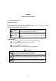
CHAPTER 1 OPERATIONAL PRECAUTION 1.1 SAFETY PRECAUTION Meanings of symbols The following symbols are used in this Instruction Manual in order to make use of the printer properly and prevent the printer from being damaged. Follow the instructions marked with the symbol. WARNING Failure to follow the guidelines marked with this symbol could result in severe personal injury or death.
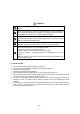
CAUTION Do not drop any metallic objects or liquids such as water or coffee into the printer. Never use the printer in a place of extreme humidity or any place where it can possibly be splashed by any liquids. If any liquids get into the printer, it could lead to fire, electric shock, or other serious accidents. Never touch the thermal head immediately after printing because it becomes very hot. Make sure that the thermal head is cool before setting papers or cleaning the thermal head.
1.3 NOTES ON TREATMENT OF THERMAL PAPERS The surface of thermal paper is specially processed using the chemical agent. And the color rises through the thermo chemical reaction process. Be aware of the following points. 1) 2) 3) 4) 5) 6) Store the papers in a dry, cool and dark place. Do not rub the papers with hard substance. Keep the papers away from organic solvent. Do not let the papers touched with vinyl chloride film, eraser or adhesive tapes for hours.
1-4
CHAPTER 2 TERMS USED IN THIS MANUAL This chapter describes the terms used in this manual. Dot A character or graphic image is composed of picture elements called dots. A dot corresponds to one of the thermal head heat elements. Dot line A line of dots arranged perpendicular to the paper feed direction. line corresponds to a line of thermal head heat elements. One dot line consists of 384 dots in DPU-30. Character spacing The space separating contiguous characters on one character line.
One line full print The printing executed when the data in the line buffer exceeds one line. Character data for one line is stored in the line buffer. When inflowing data exceeds the number of characters that can be stored in the line buffer, the data in the line buffer are printed. The overflowing data is stored at the beginning of the next line. Kanji size characters Kanji and user-defined characters. Standard size characters Extended graphics characters, katakana, and downloaded characters.
CHAPTER 3 PREPARATIONS AND OPERATION This section describes the information necessary to use the printer connecting to a host device such as the part names and dimensions of the printer, and how to set the functions. 3.
DIMENSIONS 単位:mm Dimensions of the printer 96+0/-0.5 7.5 9 0 ° 111 .2+0/-0.5 約 Approx. 90º 50 101 11 61 11 0 95 52 24 .5 11 6 (24.5) 1. Dimensions 取 り 付 け 穴 寸of 法 the 図 fitting hole 3.
Dimensions of the fixing bracket 固定金具条件 固定金具参考図 φ 6 1102 02 2- 3. 2- φ3.6 5 522 (25) (2 5) 2244 225 5 2. 44.5 - Panel thickness + 0.5 ± 0.3 45.5-板厚+0.5 ±0.3 Panel thickness 板厚 44.5 - Panel thickness + 0.5 ± 0.2 44.5-板厚+0.5 ±0.2 単位:m m Unit: mm 44.
3.3 INSTALLATION 1. How to Install the Fixing Bracket Use the サー spacers as much you need スペー を必要 なぶas ん重ね て使 用す る。 Figure 3-5 Installing the Fixing Bracket ∗ Use the spacers depending on the fitting panel thickness referring to the next table. If not, the body may be deformed, and therefore it may be hard to open the paper cover or printing quality may be deteriorated. (If the fitting panel thickness exceeds 2.2 mm, it may be hard to tighten the screws.) Panel thickness 1.0 mm 1.2 mm 1.5 to 1.
① ② ③ Figure 3-6 ③ Setting Paper 3-5
3.4 SETTINGS OF THE FUNCTIONS Printer functions can be set with the dip switches. The indicates the factory default setting. Table 3-1 No 1 to 4 5 6 7 to 8 9 0 DIP Switch Setting Function OFF Communication method Bit length Flow Command mode Direction Test pin Table 3-2 ON See Table 3-2. 8BIT RTS/CTS See Table 3-3.
3.4.1 Test Print The detail of the setting by dip switches is confirmed by test printing. In the test print mode, characters (ANK, Kanji) and barcode are printed. Turning power ON with the !FEED_IN signal kept low starts the test print. 3.4.2 Hex Dump Print In the hex dump mode, the printer prints data input from the computer with hexadecimal numbers and characters. Set the dip switch No.7 ON, No.8 OFF, and turn the power on to enter the HEX dump mode.
3.4.5 Resetting the Printer While Printing When the data with a lot of dots is printed, the print data may be missing and then, the printing may often continue in the state that each setting by the commands is reset. This is because too many print dots decrease the voltage, which results in the activation of the reset circuit of the printer.
CHAPTER 4 INTERFACE This chapter describes information that is required when using the printer connected to a host, such as the serial and parallel interface specifications. 4.1 CONNECTOR TERMINAL LAYOUT 1. Interface and power connector terminal layout Connector (plug) : XG4A-4032(Omron) Connector signal layout 1 2 39 40 (!signal name indicates Active Low.) Table 4-1 Connector Terminal Assignment No.
into V+ and V-pins. (To avoid voltage drops.) When supplying the power through the DC socket, be sure to leave V+ and V- unconnected. Never supply the power into V+ and V- terminals, and never short V+ and V- terminals. ∗ ∗ ∗ ∗ Use terminal numbers 22, 23 or 26 as the signal ground for RS-232C. Short terminal numbers 25 and 26 to feed the paper. SEL LED lights up at the time on-line by connecting it to terminal numbers 27 and 28.
4.2 PARALLEL INTERFACE 1. Data input timing DATA0 to 7 T3 T1 T2 STROBE T4 T5 BUSY T6 T7 ACK T1 T2 T3 T4 T5 T6 T7 4.3 Min. Max. Unit 0.1 0.5 0.5 − 0 0.5 − − − − 0.5 − − 1.0 µs µs µs µs µs µs µs SERIAL INTERFACE 1. Hardware control The RTS signal (Low or High) controls the transmission of the data from a host computer. When the data stored in the input buffer of the printer exceeds 4,046 bytes, the RTS signal turns Low.
Data timing for hardware control RTRTS S R xRxD D フ ゚ Print リン ト Paper 紙 無out し Power ON 電 源 ON ON-LINE ON -L I NE OF F- L IN E OFF-LINE Buffer ハBuffer ゙ ッフ ァ バ ッ ファ 4,046 bytes 40 46 バ イ ト 以 上 3,995 3 99 5bytes バ イ トor以less 下 or more 2. Xon/Xoff control The data transmission from a host computer is controlled through the exchange of Xon(1116) command and Xoff(1316) command between the printer and the host computer.
3.
4-6
CHAPTER 5 COMMAND FUNCTION This chapter describes the functions of the commands processed by the printer. 5.1 FUNCTION OUTLINE DPU-30 has two sets of commands: Mode 1/Mode 2 and Mode 3. The commands are as listed below: 5.1.1 Mode 1/Mode 2 1.
5.1.2 Mode 3 1. Paper feed commands Command CR LF FF ESC J ESC j ESC d ESC C Function Carriage Return Line Feed Page Length Print Print and Feed Forward Print and Feed Backward Print and Continuous Line Feed Page Length Set See page 5-12 5-12 5-12 5-13 5-13 5-13 5-14 2. Tab commands Command HT ESC D Function Horizontal Tab Horizontal Tab Set See page 5-15 5-15 3.
5. Character selection commands Command ESC M ESC R ESC & ESC ? ESC % Function See page Font Select International Character Select Downloaded Character Register Downloaded Character Delete Downloaded Character Specify and Clear 5-23 5-24 5-25 5-25 5-26 Function See page 6. Barcode commands Command GS H GS w GS h GS k HRI Character Printing Set Width of Barcode Set Height of Barcode Set Barcode Print 5-27 5-27 5-28 5-29 7.
9. Bitimage commands Command ESC ∗ GS ∗ GS / Function Bitimage Select Downloaded Bitimage Register Downloaded Bitimage Print See page 5-37 5-38 5-39 10. Kanji commands Command FS & FS .
5.2 FUNCTION CODES All commands start with one of the following control codes (called function codes hereinafter): LF (0A16), CR (0D16), SO (0E16), SI (0F16), DC2 (1216), DC3 (1316), CAN (1816), ESC (1B16), FS (1C16), DEL (7F16) Some function codes form a command by itself and others are followed by parameters and/or image data. The number of bytes configuring a command differs from command to command. The shortest commands consist of 1-byte and the longest, some hundred bytes. 5.
• The second byte 0016 through 1F16: The first byte already entered is ignored. Function codes are processed as function codes. All the other codes are ignored along with the first byte. If the following code accompanies a Kanji mode clear command, the next received data is processed as a 1-byte character code. Ignored along with the first byte. 2016: 2116 through 7E16: Print Kanji or user-defined characters if the first byte is one of 2116 through 7E16. Ignored along with the first byte.
5.4.2 Mode 1/Mode 2 1. Basic command CR Carriage Return Code Function Details 0D16 Prints the data stored in the print buffer, and then starts a new line according to the defined amount of paper feed for one line. • After executing this command, a head of a line is set as a starting position of printing. • LF command received immediately following CR is ignored. • The amount of paper feed for one line is fixed at 24-dot pitch.
SI Double–Width Printing Mode Clear Code Function 0F16 Clears the double−width printing. CAN Code Function Details Cancel 1816 Clears the print buffer. • After executing this command, a head of a line is set as a starting position of printing.
(Input image) (Deploy ment image) d1 d2 d3 MSB d1 d2 d3 LSB ESC c Code Function Details Special Character Specify 1B16 + 6316 Replaces the character code table from F916 to FD16 as follows. Category F916 FA16 FB16 FC16 FD16 1 (default value) 2 市 Σ 区 μ 町 Ω 村 π 人 δ • The operation is executed as a toggle operation. • The table is changed when this command is executed.
2. Extension commands ESC @ Code Function Details Initialization 1B16 + 4016 Initializes the printer. • • • • • The allocation of the user memory is initialized. The receive buffer is retained. The print buffer is cleared. The settings of each command are initialized. ROM SW is reread. DC2 > n Code Print Drive Mode Select 1216 + 3E16 + n Domain of 0 ≤ n ≤ 2 function Function Sets the print drive mode.
DC2 % n Code Print Drive User Define 1216 + 2516 + n Domain of 1 ≤ n ≤ 16 function Function Executes the printing according to the print drive defined by a user. n = 1: The amount of 1 × 8 dots n = 16: The amount of 16 × 8 dots Details • When one line is printed, the number of division is calculated every n × 8 dots.
5.4.3 Mode 3 1. Paper feed commands CR Carriage Return Code Function Details 0D16 Prints the data stored in the print buffer, and then starts a new line according to the defined amount of paper feed for one line. • After executing this command, a head of a line is set as a starting position of printing. • LF command received immediately following CR is ignored. LF Line Feed Code Function Details 0A16 Provides the same function as CR.
ESC J n Code Print and Feed Forward 1B16 + 4A16 + n Domain of 0 ≤ n ≤ 255 function Function Prints the data stored in the print buffer, and then feeds paper n × dot pitch forward. Details • After executing this command, a head of a line is set as a next starting position of printing. • This function is not affected by the setting of the amount of line spacing.
ESC C n Code Page Length Set 1B16 + 4316 + n Domain of 1 ≤ n ≤ 255 function Function Details Sets the amount of page feed. • The page feed is executed using the FF command.
2. Tab commands HT Horizontal Tab Code Function Details 0916 Moves the printing position to the position of the next horizontal tab. • If the position of the horizontal tab is not set, this command is ignored. • If the position of the horizontal tab is out of the printing area, it is set at the head of the next line. • The position of the horizontal tab is set using the ESC D command. • The default value of the horizontal tab is 8 character pitches. ESC D n1...
3. Form commands ESC 2 Code Function Default Amount of Line Spacing Specify 1B16 + 3216 Restores the amount of paper feed for one line to its default value. ESC 3 n Code Amount of Line Spacing Set 1B16 + 3316 + n Domain of 0 ≤ n ≤ 255 function Function Details Sets the amount of paper feed for one line at [n × dot pitch]. • The default amount of paper feed for one line, n = 28.
GS L nl nh Code Left Margin Set 1D16 + 4C16 + nl + nh Domain of 0 ≤ nl ≤ 255 function 0 ≤ nh ≤ 255 Function Details Sets the left margin at [(nh × 256 + nl) × dot pitch]. • This setting is only valid at a head of a line. • The maximum settable left margin corresponds to the horizontally printable area. • When a setting value exceeds maximum value, the setting value is replaced within printable maximum area. • In default, nh and nl = 0.
ESC $ nl nh Code Absolute Position of Printing Area Specify 1B16 + 2416 + nl + nh Domain of 0≤ nl ≤ 255 function 0 ≤ nh ≤ 255 0 ≤ nh × 256 + nl ≤ 127 Function Details Sets the printing area at the absolute position based on the left margin. The setting range is [(nh × 256 + nl) × dot pitch]. • This setting is only valid at a head of a line. • The value of setting exceeding the maximum value of nh or nl invalidates this command.
4. Character decoration commands ESC ! n Code Decorated Characters Collectively Specify 1B16 + 2116 + n Domain of 0 ≤ n ≤ 255 function Function Details Collectively specifies the printing modes.
ESC G n ESC E n Code Bold Characters Specify and Clear 1B16 + 4716 + n 1B16 + 4516 + n Domain of 0 ≤ n ≤ 255 function Function Details Specifies and clears the bold characters. n = B: The bold characters are cleared. n = B: The bold characters are specified. • n is valid only for the least significant bit. • In default, n = 0. ESC { n Code Inversion (Flip) Specify and Clear 1B16 + 7B16 + n Domain of 0 ≤ n ≤ 255 function Function Specifies and clears the inversion.
ESC – n Code Underline Specify and Clear 1B16 + 2D16 + n Domain of 0 ≤ n ≤ 255 function Function Specifies and clears the underline. n = B: underline 0 dot pitch n = B: underline 7 dot pitch Details • • • • • n is valid only for the low 3 bits. This setting is valid only for the standard size characters. The underline is added to the width of character and the character spacing. This function is not affected by the setting of the amount of line specing.
GS B n Code Reverse Character Specify and Clear 1D16 + 4216 + n Domain of 0 ≤ n ≤ 255 function Function Details Specifies and clears the reverse characters. n = B: The reverse characters are cleared. n = B: The reverse characters are specified. • n is valid only for the least significant bit. • In default, n = 0.
5. Character selection commands ESC M n Code Font Select 1B16 + 4D16 + n Domain of 0 ≤ n ≤ 255 function Function Details Selects the character font. n = B: character font (12 × 24 and 24 × 24) n = B: character font (8 × 16 and 16 × 16) • n is valid only for the least significant bit. • This setting is also valid for Kanji. • The character font can be set by ESC ! command but the setting by the command which has been processed at last becomes valid. • In default, n = 0.
ESC R n Code International Character Select 1B16 + 5216 + n Domain of 0 ≤ n ≤ 7 function Function Details Selects a set of characters of each country described below. When selecting JAPAN, the set of characters corresponds to the katakana – compliant character code table (refer to APPENDIX B. DATA CODE TABLE.).
ESC & y c1 c2 [x1 d1...d(y×x1)]...[xk d1...d(y×xk)] Code Downloaded Character Register 1B16 + 2616 + y + c1 + c2 [x1 d1...d (y × x1)]...[xk d1...d (y × xk)] Domain of y = 3 function 2016 ≤ c1 ≤ c2 ≤ 7E16 0 ≤ x ≤ 12 (When font (12 × 24) is selected) 0 ≤ x ≤ 9 (When font (8 × 16) is selected) 0 ≤ d1…d (y × xk) ≤ 255 Function Details Defines the downloaded pattern for the specified character code.
ESC % n Code Downloaded Character Specify and Clear 1B16 + 2516 + n Domain of 0 ≤ n ≤ 255 function Function Details Specifies and clears the downloaded character set. n = B: The downloaded character set is cleared. n = B: The downloaded character set is specified. • n is valid only for the least significant bit. • When clearing the downloaded character set, specify the internal character set.
Image of registration Font 12 × 24 Font 8 × 16 d1 d4 ⋅⋅⋅ d34 d1 d4 ⋅⋅⋅ d25 d2 d5 ⋅⋅⋅ d35 d2 d5 ⋅⋅⋅ d26 d3 d6 ⋅⋅⋅ d36 d3 d6 ⋅⋅⋅ d27 Character output range Font 12 × 24 Font 8 × 16 d1 d4 ⋅⋅⋅ d34 d1 d4 ⋅⋅⋅ d22 d2 d5 ⋅⋅⋅ d35 d2 d5 ⋅⋅⋅ d23 d3 d6 ⋅⋅⋅ d36 ⋅⋅⋅ 5-27 MSB LSB
6. Barcode commands GS H n Code HRI Character Printing Set 1D16 + 4816 + n Domain of 0 ≤ n ≤ 255 function Function Details Specifies the printing position of the HRI characters when printing a Barcode. n = B: HRI characters are not printed. n = B: HRI characters are printed on top of the Barcode. n = B: HRI characters are printed below the Barcode. n = B: HRI characters are printed on top of and below the Barcode. • n is valid only for the low 2 bits.
GS h n Code Height of Barcode Set 1D16 + 6816 + n Domain of 1 ≤ n ≤ 255 function Function Details Sets the height of Barcode. • In default, n = 162.
GS k m d1...dk NUL Code Barcode Print 1D16 + 6B16 + m + d1...dk + NUL Domain of 1 ≤ m ≤ 7 function The values of d1 to dk depend on a type of Barcode. Function Selects a type of Barcode and prints the Barcode. m 1 2 3 4 5 6 7 Details Type of Barcode UPC-E JAN13 JAN8 CODE39 ITF CODABAR CODE128 • • • • • • This command is finished by a NUL code. UPC−E is the 7-byte Barcode data and internally adds a check digit. JAN13 is the 12-byte Barcode data and internally adds a check digit.
7. Ruled line control commands DC3 A Code Function Details Ruled Line Buffer A Select 1316 + 4116 Selects the ruled line buffer A. • This function selects the ruled line buffer A. • There are 2 independent buffers (A and B) as the ruled line buffer. • The ruled line buffer A is selected as the default. DC3 B Code Function Details Ruled Line Buffer B Select 1316 + 4216 Selects the ruled line buffer B. • This function selects the ruled line buffer B. • The ruled line buffer A is selected as the default.
DC3 D nl nh Code Write in Position Specified by Dot in Ruled Line Buffer 1316 + 4416 + nl + nh Domain of 0 ≤ nl ≤ 255 function 0 ≤ nh ≤ 3 Function Details Writes 1 in the specified position in the ruled line buffer. The position is set at [(nh × 256 + nl) × dot pitch]. • Regardless of the printable area, this function writes 1 in the selected ruled line buffer. • nh is valid only for the low 2 bits.
DC3 + Code Function Details Print Mode of Ruled Line Approve 1316 + 2B16 Approves the print mode of the data stored in the ruled line buffer. • When a printing command (CR, LF, etc.) is executed after the approval, the data stored in the selected ruled line buffer is always included in the data to be printed. • This command is not affected by the printing area commands such as GS L, and GS W. • In default, the print mode of the data stored in the ruled line buffer is prohibited.
8. Response commands (only for serial mode) GS a n Validity / Invalidity of Automatic Status Transmission and Real Time Command Select Code 1D16 + 6116 + n Domain of 0 ≤ n ≤ 3 function Function Specifies the validity or invalidity of the automatic status response which is one of the printer statuses. Specifies the validity or invalidity of the real time command. n = 0: The automatic status response becomes invalid. n = 1: The automatic status response becomes valid. And the current status is returned.
GS r n Code Status Transmit 1D16 + 7216 + n Domain of 0 ≤ n ≤ 255 function Function Details Returns the current printer status. n = B : The status is returned • n is valid only for the least significant bit. • Regardless of the validity of the automatic status response, this function returns the current status. • For the status values, refer to Table 5-1 Status Response Value Table.
DLE EOT n Code Status Transmit in Real Time 1016 + 0416 + n Domain of n = 1 function Function Details Returns the current printer status in real time. • Regardless of the validity of the automatic status response, this function returns the current status. • For the status values, refer to Table 5-1 Status Response Value Table. • This command is executed at the reception. • When the real time command is invalid, this command is ignored.
DLE ENQ n Code Major Buffers Clear in Real Time 1016 + 0516 + n Domain of n = 1 function Function Details Clears the major buffers in real time while off line. n = 1: The major buffers are cleared. • This command is valid while off line. • This command is executed at the reception. • When the real time command is invalid, this command is ignored. • Users should be aware that even if this command is valid and consistent with DLE ENQ 1 in the image data, this command will be executed.
9. Bitimage commands ESC ∗ m nl nh [d1...dk] Code Bitimage Select 1B16 + 2A16 + m + nl + nh + [d1...dk] Domain of m = 0,1,32,33 function 0 ≤ nl ≤ 255 0 ≤ nh ≤ 3 0 ≤ d ≤ 255 Function Details Specifies the Bitimages with the number of dots specified as nl and nh in Mode m.
8-dot bitimage d1 d2 d1 d2 d3 d3 LSB 24-dot bitimage d1 d4 MSB d7 d1 - - - - - - - - - - d9 d2 d5 MSB d8 Double density d3 d6 Single density d9 LSB GS ∗ x y [d1...d(x × y × 8)] Code Downloaded Bitimage Register 1D16 + 2A16 + x + y + [d1...d (x × y × 8)] Domain of 1 ≤ x ≤ 255 function 1 ≤ y ≤ 48 0 ≤ d ≤ 255 (x × y × 8) ≤ Empty space of user memory Function Defines the downloaded Bitimage with the number of dots specified as x and y.
GS / m Downloaded Bitimage Print Code 1D16 + 2F16 + m Domain of 0 ≤ m ≤ 3 function Function Prints the downloaded Bitimage in the specified Mode m. m 0 1 2 3 Details Print mode Description Normal mode Double width mode Double height mode Double height and width mode Prints the normal size characters Prints the double-width characters Prints the double-height characters Prints the double-height and double−width characters • If the downloaded Bitimage is not defined, this command is ignored.
10. Kanji commands FS & Code Function Details Kanji Mode Specify 1C16 + 2616 Specifies the kanji mode. • The Kanji Mode Specify is valid only when the JIS code is selected. • If the kanji mode is selected, each and every character code is processed as 2 byte kanji code. • In default, the kanji mode is cleared. FS . Kanji Mode Clear Code Function Details 1C16 + 2E16 Clears the kanji mode. • The Kanji Mode Clear is valid only when the JIS code is selected.
FS S nl nr Code Character Spacing for Kanji Set 1C16 + 5316 + nl + nr Domain of 0 ≤ nl ≤ 127 function 0 ≤ nr ≤ 127 Function Details Sets the amount of the left (nl) and right (nr) spacing for kanji. • The amount of character spacing for normal size kanji is set. And the amount of character spacing proportionally increases according to [character scaling factor × the amount of character spacing]. • When the value exceeds the maximum, such value is set at the maximum value.
FS ! n Code Print Mode for Kanji Collectively Specify 1C16 + 2116 + n Domain of 0 ≤ n ≤ 255 function Function Collectively specifies the print mode for kanji.
FS – n Code Underline of Kanji Specify and Clear 1C16 + 2D16 + n Domain of 0 ≤ n ≤ 255 function Function Sets the underline of kanji. n = B: Underline dot pitch: 0 n = B: Underline dot pitch: 7 Details • • • • n is valid only for the low 3 bits. This command is valid only for kanji. The underline is added to the width of characters and the character spacing.
FS 2 c1 c2 d1...dk Code User–Defined Character Register 1C16 + 3216 + c1 + c2 + d1...dk Domain of 0 ≤ d ≤ 255 function k = 72 c1 and c2 depend on the kanji code system. Kanji code system JIS code Shift JIS code Function Details c1 7716 EC16 c2 2116 ≤ c2 ≤ 2F16 4016 ≤ c2 ≤ 4E16 Registers the codes specified (c1 and c2) as the user-defined characters. • c1 = first byte and c2 = second byte. • d means the image data, the bit = 1 printed, and the bit = 0 not printed, respectively.
Image of registration Font 16 × 16 Font 24 × 24 d1 d4 ⋅⋅⋅ d70 d1 d4 ⋅⋅⋅ d70 d2 d5 ⋅⋅⋅ d71 d2 d5 ⋅⋅⋅ d71 d3 d6 ⋅⋅⋅ d72 d3 d6 ⋅⋅⋅ d72 MSB LSB Character output range Font 16 × 16 Font 24 × 24 d1 d4 ⋅⋅⋅ d70 d1 d4 ⋅⋅⋅ D46 d2 d5 ⋅⋅⋅ d71 d2 d5 ⋅⋅⋅ D47 d3 d6 ⋅⋅⋅ d72 ⋅⋅⋅ 5-46
11. Function and setting commands ESC @ Code Function Details Initialization 1B16 + 4016 Initializes the printer. • • • • • The allocation of the user memory is initialized. The receive buffer is retained. The print buffer is cleared. The settings of each command are initialized. ROM SW is reread. CAN Code Function Details Print Buffer Clear 1816 Clears the print buffer. • After executing this command, a head of a line is set as a starting position of printing.
DC2 D n Code Registration Area of Downloaded Character Ensure and Release 1216 + 4416 + n Domain of 0 ≤ n ≤ 255 function Function Ensures and releases the registration area of the downloaded characters. n = B: The registration area of the downloaded characters is released. n = B: The registration area of the downloaded characters is ensured. Details • If the registration area is released, the area is added to the empty space of the user memory.
DC2 > n Code Print Drive Mode Select 1216 + 3E16 + n Domain of 0 ≤ n ≤ 2 function Function Sets the print drive mode. n 0 1 2 Details Print drive mode Feature High speed mode The printer is driven at high speed and high electric power. Medium speed mode 1 The printer is driven at medium speed and low electric power. Medium speed mode 2 The printer is driven at our recommended electric power.
DC2 % n Code Print Drive User-Define 1216 + 2516 + n Domain of 1 ≤ n ≤ 16 function Function Executes the printing according to the print drive defined by a user. n = 1 : The amount of 1 × 8 dots n = 16 : The amount of 16 × 8 dots Details • When one line is printed, how many times the line is divided is determined depending on the amount of n × 8 dots.
APPENDIX A. SPECIFICAIONS General specifications □ Printing method Thermal line dot □ Data input Parallel type Serial type 8-bit parallel (Handshake by STROBE and BUSY) RS-232C (2400 to 38400 bps, BUSY control, Xon/Xoff control) □ Dot density 8 dots/mm □ Maximum printing speed 20 mm/s max. (Power supply 5 V) 50 mm/s max. (Power supply 8.
(4) Printable character 32 characters with standard characters (24 dot standard characters with character spacing of 0 dot) □ Horizontal dot pitch 0.125 mm □ Paper feed pitch 0.125 mm □ Useful service life (at 25 °C and the rated energy) Pulse resistance 100 million pulses or more (percentage of print: 12.5%) Abrasion resistance 50 km or more □ Power supply (1) Connector for interface DC 5 V to 8.7 V (2) DC socket input: DC 8.
□ Thermal papers used • Product No.: TP-211C-1(10 rolls per box) • Paper width: 58 mm • Outer diameter of roll paper: φ50 mm or less • Core: included ∗ Use the specified thermal paper. If you use another type of thermal paper, the quality of print and the useful service life of the thermal head may not be guaranteed.
A-4
APPENDIX B. DATA CODE TABLE Katakana compliant characters (gothic) * * High order bit Low order bit * * High order bit Low order bit • SP means space. • The codes for blank cells are ignored. • The codes in the heavy line frames are function codes. * The characters of a line are not printed in Shift-JIS code.
PC 437 type High order bit Low order bit High order bit Low order bit • SP means space. • The codes for blank cells are ignored. • The codes in the heavy line frames are function codes. NOTE) Above DATA CODE TABLE shows the form of a character to the last, and does not show the actual printing pattern itself.