USER MANUAL SEIKO Precision FB – 390 Dot-Matrix Flatbed Printer
Important Safety Instructions 1. 2. 3. Read all of these instructions carefully and thoroughly and save them for later reference. Follow all warnings and instructions in the manual as well as marked on the product. Unplug this product from the power outlet before cleaning. Do not use liquid or aerosol cleaners. Use a damp cloth for cleaning. 4. Do not use this product near water. 5. Do not place this product on an unstable cart, stand or table.
Table of Contents Chapter 1 Overview.............................................................................................................. 1 Features ................................................................................................................................................ 1 Chapter 2 Preparation....................................................................................................... 3 Unpacking .....................................................................
Chapter 4 Printing from Your Software .................................................... 14 Setting Up Your Printer To Work With Software .............................................. 14 Chapter 5 Control Panel ............................................................................................... 15 Control Panel Keys and LEDs ......................................................................................... 15 Basic Control Panel Operations ..............................................
Specifications ................................................................................................................................ 28 General ............................................................................................................................................ 28 Print Head ..................................................................................................................................... 28 Mechanism .......................................................
Chapter 1 Overview Features Thank you for purchasing this SEIKO Precision FB-390 printer. Combing high speed, high quality output with advanced paper handing capabilities, this versatile, 24-pin, flatbed printer is ideal for a wide range of multi-part and cut-sheet printing requirements. Reliability, flexibility and ease-of-use are key features, making the FB-390 the perfect choice for performing demanding applications in a variety of environments.
Automatic Interface Switching The FB-390 is equipped with two interface connectors and therefore accepts both parallel (Centronics) and USB data transfer. The printer automatically detects the type of data transfer received from the host computer and switches to the corresponding interface type. High Resolution Graphics A maximum resolution of 360×360 DPI enables the printer to produce fine, sharp graphics.
Chapter 2 Preparation Unpacking Check each item against the following packing list, if any of these items are missing, please contact your local dealer. NOTE Hold the bottom of printer in the box, then carefully lift it upwards. As you unpack, save all the original packing materials if possible. They are specially designed to protect the printer and will make repacking easy if necessary. Before you start using your new printer, please make sure to remove all the shipping pads from the printer.
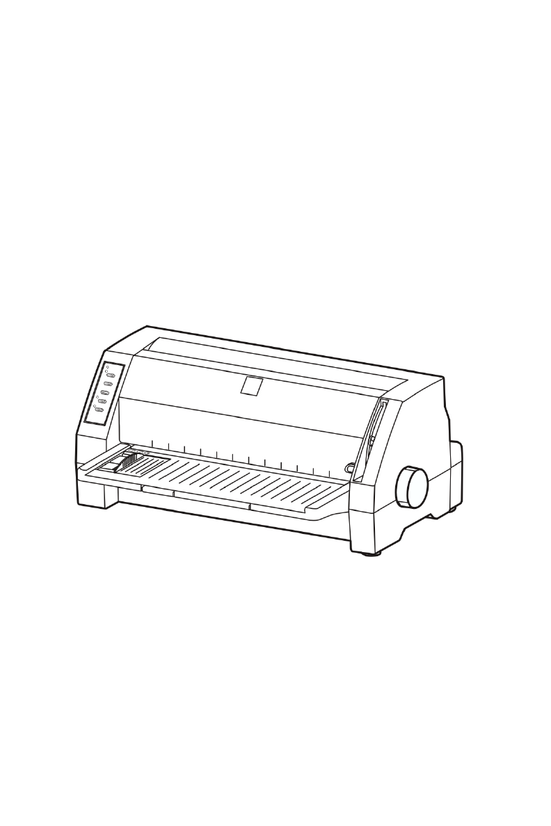
Parts Identification Figures 2-2 and 2-3 highlight the main components of the printer.
Installation Before placing the printer in your chosen location, consider the following guidelines: This printer should be placed on a normal table, printer stand or desk. Be sure that the surface is level, to avoid an uneven load on the carriage as it operates. Do not install the printer where it may be subjected to unsuitable conditions such as: ·Where there is excessive dust. ·Where it may be splattered with oil or metallic dust. ·Where it may be exposed to direct sunlight.
3 4 5 6 Pull the Sub friction roller by gripping the center area of the unit by your forefingers. Then lift it up until it is positioned upwards towards the top of the printer as shown in Figure 2-5. If necessary, move and centre the print head carefully by hand. Hold the ribbon cartridge with the knob facing upwards and turn the ribbon knob in the direction shown by the arrow to take up any slack in the ribbon.
Using the Parallel Interface and the USB Interface The parallel interface The USB interface Parallel interface connector USB interface connector Parallel interface cable USB interface cable Figure 2-7 Connecting the parallel interface cable and the USB interface cable Connecting to the Power Source Connecting the Power Cord Plug the power cord (supplied) into the power inlet at the rear of the printer.
Chapter 3 Loading paper Paper Thickness Adjustment Before loading cut sheet or tractor paper, you have to adjust the gap adjust lever on the front right side of the printer. To feed thicker papers through the printer, you need to move the gap adjust lever from its standard position. The lever moves the print head relative to the platen so that there is more room for the paper. Adjusting the gap adjust lever To obtain good quality printing and prevent problems (paper jam etc.
Loading Cut Sheet Paper 1 2 Turn the printer on. Set paper select lever toward the back of printer as shown in Figure 3-2. Figure 3-2 Setting the paper select lever 3 4 Set the gap adjust lever for example to the position “1” for thin paper. Position the left cut sheet guide by referring to the marking on the window cover. The positions for A4 and Letter size paper are indicated on the left side of the window cover as shown in Figure 3-3.
position. You can set the printer to detect skew so if the paper skews during loading, the printer detects it and automatically ejects the paper to the front table. Figure 3-5 Loading cut sheet 7 After the above steps, the printer is ready to print. NOTE The printer’s skew detection level can be set within the Setup Menu System. Be careful with the lowest possible setting because the printer might reject the paper due to even the smallest skew. If this happens, try a more medium setting.
3 Move the left cut sheet guide to the far left as much as possible. Figure 3-8 Moving the left cut sheet guide to the far left 4 Release the lock lever of tractor. Figure 3-9 Releasing the lock lever of the right tractor (view from rear) 5 Move the left tractor to the left proper position (The “0”position indicates the horizontal starting print position). When moving the left tractor to the leftmost position, the distance between the starting print position and the centre of the sprocket pins is 11.
Figure 3-11 Adjusting the paper guide pulley position 7 Open the tractor covers and place the paper on the sprocket pins. If you are using preprinted paper or labels, install them with the printed or labeled side facing upwards. Figure 3-12 Setting paper on the sprocket pins 8 Close the tractor covers. Figure 3-13 Close the tractor covers. 9 Slide the right tractor to the left to take up any slack in the paper, and then fasten the lock lever to fix the tractor in position.
The lock lever Figure 3-14 Locking the position of the right tractor 10 When starting a new print task, the printer will automatically load the paper before the actual printing starts. (You can also press the PARK/LOAD key to load the paper manually.) Tearing off Tractor Paper To tear off the paper, make sure that printed-paper is fed to the front table. If not, switch the printer offline then press the PARK/LOAD key.
Chapter 4 Printing from Your Software Setting Up Your Printer To Work With Software The printer supports the Epson ESC/P2 emulation. You can select the Epson LQ-570+ driver for this printer, but the best way to ensure that all the features of your printer are supported by the software is to use the SEIKO Precision printer driver. If the driver is not available in your software package please call your software company.
Chapter 5 Control Panel Control Panel Keys and LEDs The control panel consists of five keys and four LEDs as shown in Figure 5-1 Figure 5-1 The printer control panel The following table details each indicator LED function: Indicator LED On Off POWER (green) Lights when the printer is turned on. It flashes when paper runs out and during error condition (See Appendix A) The printer is turned off. ONLINE (green) Lights when the printer is online.
Basic Control Panel Operations You can use the five keys on the control panel to operate your printer. ONLINE Pressing the ONLINE button, toggles between ONLINE and OFFLINE mode. PARK/LOAD In the offline mode, pressing the PARK/LOAD button shortly controls feeding tractor paper or cut sheets LF/FF In the offline mode, press the LF/FF key to feed the paper line by line.
LF/FF: Decrease the top of form by 1/60 inch. You can decrease the margin to a maximum of -10 (-10/60 inch) from the default setting. Press the ONLINE key to exit and save your new setting. The POWER LED and ONLINE LED blink simultaneously 3 times with a beep, and then the POWER LED will be on. NOTE To exit without saving, just turn the printer OFF. Tear-off Adjustment Mode There is a tear-off bar at the edge of the window cover.
menu lists, each list containing several settings. You can select a new setting of the menu list and save it, or just go to the next menu list without altering the current setting. To enter the Setup Menu System and change the settings 1. Lift the window cover of the printer. 2. Eject any paper currently in the printer (or park tractor paper) then switch the printer ONLINE. 3. Keep pressing the PARK/LOAD key for 3 seconds. This starts the Setup Menu System and prints the instructions for using it.
Printing the Current Setting Report You can use the information in the current setting report to decide which setting you want to change. To print the current settings: 1. Turn the printer off. 2. Hold down both the PARK/LOAD and LF/FF key at the same time 3. Turn the printer on. The printer automatically loads paper and prints the current settings. An example print out is shown in Figure 5-2.
SEIKO Precision FB-390 Current Setting Report Current settings are FILLED . PRINT STYLE FONT PITCH PAGE LAYOUT LINE SPACING FORM LENGTH PAGE SKIP COMPRESS PRT PRINT MODE TEXT DIR GRAPHIC DIR CHARACTER SLASH ZERO CHARACTER SET INTL CHAR SET CODE PAGE ROMAN 10 CPI 6 LPI A4 OFF NORMAL BI-DIR UNI-DIR OFF GRAPHICS U.S.A. U.S.A. INSTALL QUIET MODE OFF AUTO LF OFF AUTO TEAR OFF LOADING SKEW DETECTION OFF SKEW LEVEL 0.5 SEC. 1.0 SEC.
Options of the Setup Menu System The following printout in Figure 5-3 shows the selections from the Setup Menu System and is followed by a description of how to use it in Table 5-2 (Options of the Setup Menu System). SEIKO Precision FB-390 SETUP MENU SYSTEM Use the PARK/LOAD key to point the print head to the desired setting. Use the LF/FF key to store the new setting and go to the next menu. Use the ONLINE key to go to the next menu without storing a new setting.
Options Description FONT Set the font for the printer to use in the absence of any font control instructions from your software. PITCH Set the pitch to determine the horizontal spacing of the printed characters. LINE SPACING Set the vertical spacing of the printed characters. You can set it to either 6 LPI (the default setting) or 8 LPI. FORM LENGTH Set the length of your printer paper, for both cut sheets and continuous-feed paper.
Restoring Factory Printer Settings You can restore to the factory printer settings without having to work through the Setup Menu System to reset the menus. To restore to the factory settings: 1. Make sure that the printer is ONLINE 2. Press and hold down the ONLINE and COPY keys on the control panel for 3 seconds.
Version: H PRINT MODE 390V X.X 20XX/XX/XX HHHHHHHHHHHHHHHHHHHHHHHHHHHHHHHHHHHHHHHHHHHHHHHHHHHHHHHHHHHHHHHHHHHH HHHHHHHHHHHHHHHHHHHHHHHHHHHHHHHHHHHHHHHHHHHHHHHHHHHHHHHHHHHHHHHHHHHH HHHHHHHHHHHHHHHHHHHHHHHHHHHHHHHHHHHHHHHHHHHHHHHHHHHHHHHHHHHHHHHHHHHH Figure 5-5 The former of the maintenance print Hex Dump Mode Turning power on while pressing the PARK/LOAD key causes the printer to enter Hex Dump mode.
Appendix A Maintenance and Fault Finding Introduction Your printer requires very little routine maintenance. In fact, the best maintenance for the printer is preventative. If you have followed the suggestions for locating it in an area free of excessive dust and heat it will give you a long and trouble-free performance.
NOTE Over-application of oil may cause a build up of dust and dirt with resulting printer failure. Cleaning the platen Clean the platen with a soft cloth. Intervals and Materials for Cleaning Clean inside the printer in accordance with the following: NOTE Intervals cleaning: Materials: Every 6 months or 300 hours of operation.
Printing is Smudged The ribbon is in front of the ribbon mask. Remove it and then insert it correctly. Adjust the gap adjust lever (move it downward). Poor Dot Positioning If poor dot positioning occurs, the horizontal dot alignment has to be performed by an authorized technician. Characters On The Screen Don’t Match The Printed Characters Many graphics characters and special symbols are produced by different ASCII codes on each make of computer and printer.
Appendix B Specifications General Type 24-Pin Flatbed Dot Matrix Impact Printer Fonts 1 DP (Draft) 7 LQ (ROMAN, SANSERIF, COURIER, PRESTIGE, SCRIPT, OCRA, OCRB) Emulation Epson ESC/P2 Memory 256K bytes (*Input buffer: 132K bytes) Interface Parallel Interface: Centronics (IEEE 1284 NIBBLE mode Compatible) USB Interface:USB 2.
Mechanism MODE 10 CPI 12 CPI 15 CPI Super High-Speed 300CPS 340 CPS 420 CPS 80 DPI 80 DPI 80 DPI 250CPS 300 CPS 375 CPS 120 DPI 120 DPI 120 DPI 83 CPS 100 CPS 125CPS 360 DPI 360 DPI 360 DPI Print speed DP LQ Paper feed Speed Number of columns Paper slew speed (Continuous feed): 5.
Print mode specifications Print mode Multipart Dot Spacing mode (V×H inches) Max No.
Graphic Print Specifications Graphic type Density 120dpi 180dpi 360dpi Pins 24 24 24 Horizontal dot pitch Multipart mode Print speed (inch/second) Normal、Dark 1 9.9 Dark 2 8 Dark 3 3.9 Normal、Dark 1 6.6 Dark 2 5.3 Dark 3 2.6 Normal、Dark 1 6.6 Dark 2 5.3 Dark 3 2.6 1/240 inch 1/360 inch 1/360 inch Parallel Interface Signal level Input High level: 2 to 5V, Low level: 0 to 0.8V Output High level: 2.4 to 5V, Low level: 0 to 0.4V Connector Pin Assignments Signal Pin No.
USB Interface USB 2.0 Full-Speed. The following table provides the standardized contact terminating assignments by number and electrical value for Series “A” and Series “B” connectors. Contact Number Signal Name Typical Wiring Assignment 1 VBUS Red 2 D- White 3 D+ Green 4 GND Black Shell Shield Wire Command Code Summary Epson Emulation Code (Symbol) Name Code (Hex.) Code (Dec.
Code (Symbol) Name Code (Hex.) Code (Dec.
Name Code (Symbol) Code (Hex.) Code (Dec.
Select Code Pages Format Code No. ESC ( t n1 n2 d1 d2 d3 (n1=3, n2=0, d1=0,1,2,3) d2 d3 (HEX) Name 437 1 0 U.S.A.
This printer complies with the regulation about the maximum noise level in the work place – 3. GPSGV, under which the highest noise level has to be 70 dB (A) or less in accordance with ISO7779. Maschinenlärminformations-Verordnung - 3. GPSGV, der höchste Schalldruckpegel beträgt 70 dB(A) oder weniger gemäß ISO7779. This unit complies with Low Voltage Directive 2006/95/EC and the EMC Directive 2004/108/EC.
Company name:SEIKO PRECISION (Europe) GmbH Address:Hermann-Buck-Weg 9, D-22309 Hamburg, Germany