
Installation Instructions
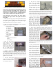

INSTALLATION INSTRUCTIONS FOR KERR
LIGHTING PRODUCTS FROM SNAP EDGE CORP.
Thank you for purchasing Kerr Lighting products. Please
read all instructions thoroughly before beginning and
follow them carefully when installing your project.
If you
need assistance, technical support is available Monday to
Friday, 8 AM to 5 PM CST by calling (800) 932-3343.
These instructions can be used for Kerr Paver Lights
™
,
Retaining Wall Lights, Garden Wall Lights and Deck &
Dock Lights.
1. Draft a layout of your project showing the location where
the transformer will be plugged in and the desired location of
your lights. Lights are typically placed 5-8 feet apart for good
lighting distribution but you may prefer otherwise.
2. Make sure you have the materials and tools needed to
complete your installation. You’ll need:
• Lights, each including
o light base
o light lens
o lamp socket(s)
o lamp(s) (bulbs)
• Connectors (2 per
light)
• Low voltage power
supply cable
• Transformer
• Tools:
Philips Head Screwdriver
Pliers
Wire Cutters
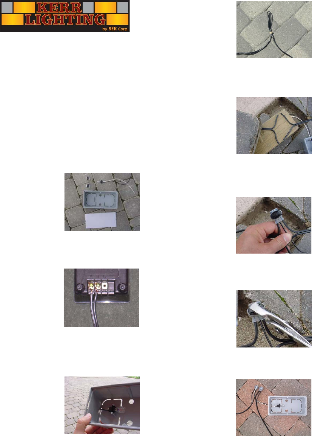
3. Split one end of the
power supply cable and
remove about ⅜” of the
insulation on each side to
expose the copper wire
inside. Connect each side to
the “A” & “B” screws on
the back of the transformer.
4. Mount the transformer indoors or outdoors near a plug.
Transformers placed near swimming pools or other water
sources should be plugged into a GFCI-protected outlet and
the control unit should be mounted at least 10 feet from the
edge of the water. Do not plug in the transformer until all
lights have been installed.
5. All Kerr Paver lights
come preassembled with the
bulbs in the sockets which
are attached to the base.
6. Run the low voltage
cable which will supply
power to the lights around
the perimeter of your
project. For installation with
segmental pavers, you may
set the cable atop the
bedding sand under the
border course of pavers to
keep it from being damaged when digging in the yard and so it
can be easily located. Form a loop in the cable where the lights
will be located (with a rubber band if desired) to leave enough
slack for connection of the light to the power cable.
7. When using the silicone
connectors cut the power
supply cable in half where
lights will be located and
split it down the middle.
Note that one side of the
cable is ribbed and one is
smooth. Do not strip the
insulation from the cable.
See back of sheet when using the brown connectors.
8. Wires will be rejoined and lights attached using the
connectors. Examine the connectors and note that there are
three holes in each. Take the ribbed side of one end of the
split power supply cable and
push it into one of the side
holes in the connector. Push
it in until it goes all the way
to the back of the connector.
Take the ribbed side of the
other end of the split power
cable and place it in the hole
on the other side, again
making sure that is it pushed all the way to the back. Finally
take the black wire from a light and place it in the center hole,
pushing it to the back of the connector. The connector should
have 3 wires in it.
9. Once you have all three
wires in each of the three
holes and pushed all the way
to the back, squeeze the
connector with a pair of
pliers to push the black cap
down. This will make the
connection between all three
wires and will require some
force. The connectors also contain silicone to protect the
connection from moisture which may squeeze out on this step;
be careful not to get it on your clothing.
10. Repeat steps 8 & 9
using the smooth sides of
the power supply cable and
the white wire from the
light. You should end up
with two connections per
light as shown. After all
lights have been attached,
plug in and switch on the
transformer to test all connections.