OWNERS MANUAL Serial No. www.lpadjustablebeds.
CONTENTS Advisory ............................................................................................................... 4 Acoustics .............................................................................................................. 6 Installation ............................................................................................................ 7 Sleep Number® Mattress Installation ............................................................... 13 Hand Control Operation .......
ADVISORY IMPORTANT INFORMATION READ THE FOLLOWING INFORMATION CAREFULLY BEFORE USING THIS PRODUCT This Precision Comfort™ adjustable foundation has been quality engineered with design features to assure comfort and safety when operated properly. ELECTRICAL GROUNDING This product is equipped with a polarized, grounded electrical power cord. The power cord will only fit into a grounded, electrical surge protection device (not included) or a grounded electrical outlet.
ADVISORY IMPORTANT INFORMATION READ THE FOLLOWING INFORMATION CAREFULLY BEFORE USING THIS PRODUCT This Precision Comfort™ adjustable foundation has been quality engineered with design features to assure comfort and safety when operated properly. This foundation is designed for in-home use only. It is not approved for hospital use and does not comply with hospital standards. Do not use this bed with tent type oxygen therapy equipment, or use near explosive gases.
ACOUSTICS LIFTING/LOWERING MECHANISMS The lift/lower feature will emit a minimal humming sound during operation. This is normal. During Precision Comfort™ operation, the lift arm wheels make contact with the platform support of the bed. This applies slight tension on the moving components and resonance is reduced to a minimum level. If excessive noise or vibration is experienced, reverse the movement action (up or down) of the bed with the hand control.
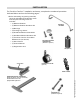
INSTALLATION For Precision Comfort™ installation and setup, complete the numbered procedure indicated below and on the following pages: 1.
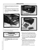
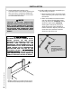
INSTALLATION 2. Carefully Lift the bed base frame from the shipping carton, keeping the unit top-sidedown. 3. Install (4) legs into the base frame. Simply screw each leg into a tapped hole at each corner of the base frame (FIGURE 1). Insert casters into the bottom of each bed leg (if applicable). POWER DOWN BOX BATTERY COMPARTMENT DOOR CASTERS – PRESS-FIT INTO BOTTOM OF LEGS (IF APPLICABLE) FIGURE 2: Receiver unit (power down box) battery compartment door removal.
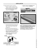
INSTALLATION 10. Install mattress retainer as follows: a. Locate (1) mattress retainer and (1) mattress retainer hardware kit (bag). b. Install (1) cupped washer, (1) spacer and (1) flat washer on (4) mattress retainer bolts (FIGURE 4). B ASSEMBLE AS SHOWN BELOW: D g. Tighten screws to complete mattress retainer installation (FIGURE 6). NOTE DO NOT USE POWER SCREWDRIVER TO T INSTALL MATTRESS RETAINER.
INSTALLATION 11. Install headboard brackets to the foundation base frame. When attaching (2) twin size units to a king size headboard, use swing-away hinges (see accessories) to connect the twin units. NOTE FAILURE TO FOLLOW HEADBOARD BRACKET INSTALLATION INSTRUCTIONS MAY CAUSE HEADBOARD BRACKET INTERFERENCE WITH BASE FOAM DURING ADJUSTABLE BED OPERATION. BASE FOAM OR BASE COVER DAMAGE COULD RESULT.
INSTALLATION USE (2) 3 INCH CARRIAGE BOLTS AND NUTS TO ATTACH EACH BRACKET CHANNEL TO THE FRAME EXTENSIONS ANGLE BRACE ANGLE BRACE SLIDE HEADBOARD BRACKET CHANNEL OVER THE FRAME EXTENSION USE (2) 1 INCH BOLTS AND NUTS (TIGHTEN) TO ATTACH HEADBOARD BRACKET FLANGE TO EACH BRACKET CHANNEL FIGURE 9: Headboard bracket channel installation (one each side of the head section of the bed). c. Attach one headboard bracket flange to one of the bracket channels with (2) bolts/nuts. (FIGURE 10) Tighten bolts.
INSTALLATION d. Slide headboard bracket assemblies (in or out) to achieve a distance of 1.5 inches (38.1mm) to 2 inches (50.8mm) between the edge of the foundation base and headboard bracket flange assemblies (FIGURE 11). e. Firmly tighten the 3 inch carriage bolts of both headboard bracket channels. f. Measure the distance (center-tocenter) between the mounting holes in the headboard. g. Measure the center-to-center distance between the mounting slots of the headboard bracket flanges (FIGURE 12). h.
Sleep Number® MATTRESS INSTALLATION INSTALLATION INSTRUCTIONS Tools required—utility knife, Phillips® head screwdriver. Install the Sleep Number® mattress, per the following procedure: 1. Verify Precision Comfort® adjustable foundation setup is complete. 2. Identify and remove (2) locator pins in the adjustable foundation (FIGURES 13 and 14). Note: approximate locator pin position is 32-1/2” from the top and 6” from the side of the adjustable foundation.
Sleep Number® MATTRESS INSTALLATION EXERCISE EXTREME CA UTION WHEN CAUTION USING UTILITY KNIFE! THE DANGER OF SERIOUS FINGER CUTS ARE POSSIBLE IF UTILITY KNIFE IS NOT USED CORRECTLY. 8. At each threaded lug location, make a small cut (no larger than 1/4” long) through the mattress cover fabric with a utility knife (FIGURE 15). 9. Position a large plastic washer over each cut in the mattress cover fabric (FIGURE 15). 10. Position a metal washer over each plastic washer (FIGURE 15). 11.
Sleep Number® MATTRESS INSTALLATION NOTE IF ADJUSTABLE FOUNDATION SERVICE IS REQUIRED, REMOVE THE SLEEP NUMBERÆ MATTRESS BEFORE THE SERVICE TECHNICIAN ARRIVES.
HAND CONTROL OPERATION TRANSMISSION INDICATOR LIGHT POSITION RECALL BUTTONS Press to recall a massage/wave setting assigned by the program set button. MASSAGE SET BUTTON Press to capture a setting of the massage and/or wave functions as a programmed position. Press the favorite massage button to activate the preset position. FOOT UP/DOWN BUTTON Press and hold to raise or lower the foot section. FLAT BUTTON Press to return bed to the level position.
RECEIVER UNIT OPERATION In case of a power outage, press and hold the learn button on the receiver unit (power down box) to lower the bed to the flat position (FIGURE 18). POWER DOWN BOX LEARN BUTTON This function is only for lowering the bed and will not operate the bed to any other position. The (2) 9 volt batteries should be replaced after this function is used. FIGURE 16: Power down box learn button.
PROGRAMMING 1 hand control - 1 bed The two step procedure below is required to program 1 hand control to operate 1 bed. Before beginning, make certain the bed is plugged into a working grounded electrical outlet. STEP 1 Locate the receiver unit (power down box) for the bed and press the learn button for 1 second and release (FIGURE 16). POWER DOWN BOX LEARN BUTTON TRANSMISSION INDICATOR LIGHT POS 1 BUTTON FIGURE 16: Power down box learn button.
PROGRAMMING 2 hand controls - 1 bed The three step procedure below is required to program 2 hand controls to operate 1 bed. Before beginning, make certain the bed is plugged into a working grounded electrical outlet. STEP 1 Locate the power down box for the bed and press the learn button for 1 second and release (FIGURE 16). POWER DOWN BOX HAND CONTROL 1 HAND CONTROL 2 LEARN BUTTON TRANSMISSION INDICATOR LIGHT POS 1 BUTTON FIGURE 16: Power down box learn button.
PROGRAMMING 1 hand control - 2 beds The three step procedure below is required to program 1 hand control to operate 2 beds. Before beginning, make certain the beds are plugged into a working grounded electrical outlet. STEP 1 Locate the power down box for bed 1 and press the learn button for 1 second and release (FIGURE 16). BED 1 POWER DOWN BOX LEARN BUTTON BED 2 TRANSMISSION INDICATOR LIGHT FIGURE 16: Power down box learn button.
PROGRAMMING 2 hand controls - 2 beds The six step procedure below is required to program 2 hand controls to operate 2 beds. Before beginning, make certain the beds are plugged into a working grounded electrical outlet. STEP 1 Locate the power down box for bed 1 and press the learn button for 1 second and release (FIGURE 16). STEP 6 Repeat Step 4 and Step 5 with hand control 2. Two hand controls are now programmed to operate two beds. POWER DOWN BOX LEARN BUTTON FIGURE 16: Power down box learn button.
PROGRAMMING separating 2 beds The six step procedure below is required to separate 2 hand controls from operating 2 beds. One hand control per bed operation will result. Before beginning, make certain the beds are plugged into a working grounded electrical outlet. STEP 1 Locate the power down box for bed 1 and press the learn button for 1 second and release (FIGURE 16). STEP 6 Repeat Step 4 and Step 5 with hand control 2.
ACCESSORIES Precision Comfort™ OPTIONAL EQUIPMENT Contact your nearest Select Comfort® retail dealer or call toll free at 800-582-7216 for accessory pricing and to order the accessories indicated in the chart below: ACCESSORY DESCRIPTION CODE Glides1 (set of 4, replaces legs) 107397 7” Legs (set of 4) 107399 Swing-away Hinges Bed Straps (connects 2 Precision Comfort foundations together) 107398 Headboard brackets cannot be used with glides.
TROUBLESHOOTING In the event the Precision Comfort™ adjustable bed fails to operate, investigate the symptoms and possible solutions provided in the chart below: SYMPTOM Hand control illuminates and appears to be operable, but will not activate bed. SOLUTION • Verify power cord is plugged into a working, grounded electrical outlet. A grounded, electrical surge protection device is recommended. Test outlet by plugging in another working appliance.
1-2-20 WARRANTY Leggett & Platt, Incorporated (“L&P”) warrants this adjustable bed to the consumer who is the original purchaser (the “purchaser”), subject to the terms and conditions set forth herein. This warranty begins on the “warranty commencement date” which is the date of purchase for new unused beds and the date of manufacture for beds that have been used as floor or display models. Thus, on a floor model bed, the warranty is a portion of the limited 20-year warranty.
1-2-20 WARRANTY Repairs to or replacement of an adjustable bed or its components under the terms of this limited warranty will apply to the original warranty period and will not serve to extend such period. The decision to repair or to replace defective parts under this warranty shall be made, or cause to be made, by L&P at its option and in its sole discretion. Repair or replacement shall be the sole remedy of the purchaser.