Instruction Manual for SP PRO Interactive Inverter Charger Installation • Operation • Service
Selectronic Australia Pty Ltd © 2014 Suite 5, 20 Fletcher Rd Chirnside Park VIC 3116 Australia Ph +61 3 9727 6600 Fax +61 3 9727 6601 www.selectronic.com.
INTRODUCTION Thank you for purchasing a Selectronic SP PRO series sine wave Interactive Inverter Charger optimised for either grid connected power systems (also called Solar Hybrid Power Systems) of Off Grid systems (no grid power available). Selectronic has an accredited Quality Assurance system to AS/ISO9001-2008 covering both their manufacturing and design operations with over 25 years experience designing power conversion equipment for both domestic and industrial purposes.
Contents Contents INTRODUCTION Australian/New Zealand Warranty Using This Manual Included in this package Glossary of Terms Benefits of SP LINK Solar Hybrid Support and Grid Feed Systems Product Overview Off Grid Stand Alone Power Systems (SPS) Mobile Systems Precautions and Safety Who should install this unit Multiple Hazardous Energy Sources Preparation Installation Maintenance Inverter may start automatically Backup Generator may start automatically Battery 6 6 7 7 7 8 8 9 9 10 10 10 11 11 11
Contents Installation-Commissioning Introduction Diagnostics during Commissioning Common System Checks Checking Managed AC coupled systems Checking Generic AC coupled Checking DC coupled Three phase and Split Phase Systems External AC Source Contactor External Generator 48 48 48 49 51 52 52 53 54 55 O P E R AT I O N Controls and Indicators 56 SP PRO Operation 58 User Interface Battery Management Battery State of Charge (SoC) monitoring and control Battery Voltage monitoring and control Battery Char
INTRODUCTION | Warranty and manual use Australian/New Zealand Warranty The Selectronic SP PRO product is warranted by the manufacturer to the original purchaser only. The manufacturer will bear the cost of parts and labour to repair any faults found within the terms and period of this warranty. For full warranty terms and conditions please see the warranty card packed with the SP PRO inverter.
INTRODUCTION | This Package and SP LINK Included in this package • • • • • • • • Mounting bracket Rear Outlet Mesh Cover (SPLC models only) Contents check list, checked and signed by Selectronic Know Your SP PRO display quick reference card Warranty card.
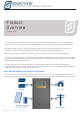
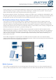
INTRODUCTION | Product Overview Product Overview Chapter One The SP PRO Sine wave Interactive Inverter Charger is designed specifically for either Solar Hybrid (grid support / grid feed) or Off Grid (no grid available) systems to simplify their installation and configuration. As a battery based inverter, charger and system controller all in the one product. each SP PRO has a configurable export power limit suitable for many export limited Solar Hybrid applications.
INTRODUCTION | Product Overview of day, battery SoC or load demands allowing the maximum use of the renewable energy (such as PV solar) and stored battery energy to supply loads to take advantage of variable electricity tariffs. A Solar Hybrid system will allow the user to only use grid electricity when they choose. By using the optional “Grid fail - Gen backup” module the SP PRO can be configured to automatically start and stop a generator during a prolonged power outage.
INSTALLATION | Precautions and Safety Precautions and S a fe t y Chapter Two Who should install this unit While the SP PRO is designed for easy installation and can be installed by any suitably qualified person, to maximize the performance of the system and tailor the configuration of the SP PRO to the specific needs we recommend the use of a Selectronic Accredited Integrator.
INSTALLATION | Precautions and Safety Preparation Whilst every effort has been made to pack the SP PRO in a way that will provide adequate protection, damage in transit can occur. Please carefully check the packaging and the SP PRO for signs of damage and for all components mentioned in the “Included in the Package” section of this manual. Please report any damage or missing parts to Selectronic or a Selectronic Authorised Distributor.
INSTALLATION | General Requirements INSTALLATION Installation- G e n e r a l Re q u i r e m e n t s Chapter Three The SP PRO must only be installed by suitably qualified personnel. Many procedures covered in the INSTALLATION sections of this manual have inherent risks. Whilst the SP PRO is designed to be safe, including safety features never before found in an inverter (such as Earth / Neutral bond monitoring), the voltages connected to or generated within the SP PRO are hazardous and potentially fatal.
INSTALLATION | General Requirements Environmental Considerations Temperature The SP PRO is designed for an ambient operating temperature between -20°C and 60°C, with a storage temperature range between –20°C and 70°C. AIR FLOW For best performance ensure nothing impedes ambient air from being drawn in the bottom of the unit and that hot exit air is vented away and doesn’t recirculate into the unit. Particular attention must be paid when installed inside a cabinet or enclosure.
INSTALLATION | General Requirements Preparation The selection of a suitable site and good preparation is essential in getting optimum performance from the SP PRO. SP PRO Inverter performance is dependant upon the environmental operating conditions, in particular ambient temperature and ventilation. In addition safety aspects must be considered, such as: • • Restrict access to authorised personnel only. Consideration of maintenance of ambient temperatures to ensure performance within product specification.
INSTALLATION | Installation of SPMC models Installation of SPMC models 1 - Unpack the SP PRO onto a flat surface. When removing the SP PRO from its packaging carefully inspect for any damage that may have occurred in transit. Damage must be reported to the supplier immediately.
INSTALLATION | Installation of SPMC models 2 - Diagram previous page. Choose a suitable weight bearing and temperature resistant surface to mount the SP PRO. Max temperature is ambient +30 degrees C, max weight is 45 kg. The display of the SP PRO should be at eye level. There should be no obstructions to the clear passage of air. Use the 6 x M8 holes to mount the bracket. If the SP PRO is being installed in a mobile situation use the optional mobile mounting bracket.
INSTALLATION | Installation of SPMC models 8- Wiring must only be carried out by suitably qualified installers and must adhere to all relevant standards. Please bear in mind that installations performed and signed off by a Selectronic Accredited Integrator will benefit from additional warranty cover. 9 When all the AC wiring is complete reinstall the terminal cover and expansion card.
INSTALLATION | Installation of SPLC models Installation of SPLC models 1 - Undo ten bolts (7/16“) to remove lid on packing crate. Cardboard tray contains mounting plate, rear air outlet mesh cover and all documentation. Inspect for damage in transit and report any to the supplier immediately.
INSTALLATION | Installation of SPLC models 2 - Cable entry is either from below or wall entry. Gland plates are inter changeable . Gland plates secure to the underside of unit base or to the inside of the mounting plate using four T25 Torx screws. 3 - See Diagram on previous page Choose a suitable weight bearing and temperature resistant surface to install the mounting plate. Max temperature is ambient +30°C, weight is 115 kg. The plate should be mounted at a convenient level.
INSTALLATION | Installation of SPLC models 7- Undo five T20 Torx screws to remove terminal plate. Expansion card remains secured to SP PRO. Note: Expansion card not shown for clarity. Note: Gland plate shown in wall entry cable position. 8 - Wiring can only be carried out by suitably qualified installers and must adhere to all relevant standards. Installations performed and signed off by a Selectronic Accredited Integrator will benefit from an additional warranty cover.
INSTALLATION | Cabling and fusing Battery Cabling Requirements The follow tables specify the minimum Recommended Copper Battery Cable Sizes for SP PRO GO inverter. NOTE: Please ensure the battery cabling and the fusing complies with relevant safety standards. Total distance per conductor from the SP PRO to the battery terminals <2m 2-5m 5 - 10 m > 10 m Minimum Size Copper Battery Cables per inverter.
INSTALLATION | Cabling and fusing DC Wiring SPMC Models WARNING: Copper wiring must be used through out.. All the SPMC models do NOT contain an internal fuse or DC breaker. The DC wiring must be fitted with appropriate fusing or circuit breakers. The fuse or circuit breaker must be located in a user accessible position and be in close proximity to the battery system. The battery system must not be accessible by the user. There are four DC wiring connections that should be made.
INSTALLATION | Cabling and fusing Expansion Card Warning - 120VDC model SPMC1201, SPLC1200 and SPLC1202 models - Hazardous Voltage - 120 V Battery Expansion card connects to both Hazardous and Safety Extra Low Voltage (SELV) wiring. The connector and wiring to J4 (marked with RED on card) MUST be treated as Hazardous and be physically segregated from other wiring connected to expansion card. Protective cover MUST be installed on the Expansion card.
INSTALLATION | Cabling and fusing Battery Wiring (DC) Preparation The below schematic diagram shows the main battery isolator, battery sense / pre-charge isolator and included temperature sensor. For 48V and 120V battery banks it is a requirement that the Battery Sense / Precharge connections are used and wired directly back to the battery bank terminals.
INSTALLATION | Cabling and fusing AC Wiring WARNING: Copper wiring must be used through out.. The SP PRO does NOT contain internal circuit breakers of fuses. The AC wiring MUST be fitted with appropriate fusing or circuit breakers. The AC cabling should be sized according to maximum demand through (consumed by the AC Load) and simultaneously consumed by the SP PRO (consumed by the charging of batteries).
INSTALLATION | Cabling and fusing AC Wiring Preparation The intended application and use of the SP PRO must be well understood to allow the SP PRO to be appropriately connected to the installation. How the SP PRO is wired into the switchboard is dependant on whether all the installation’s loads or only essential loads are to be supplied by the SP PRO for tariff optimization, self consumption or battery backup.
INSTALLATION | Cabling and fusing Backup Generator (Advanced Feature) Control Wiring When a backup generator is installed, control wiring should be fed up through the appropriate gland and terminated to the SP PRO Expansion card. The minimum required is one pair of wires for a generator run signal which must be wired to one of the four relay outputs. “CAT5” type cabling or any multi conductor multi strand cable is suitable for all control wiring.
INSTALLATION | System Configuration Installation-System Configuration Chapter Four This section details the extra information needed to install and configure standard system configurations. It is imperative that the installation details in the previous section have been followed before proceeding with the relevant installation instructions in this section.
INSTALLATION | System Configuration Managed AC Coupled Preparation For full installation details see document “IN0018_xx SP PRO KACO Managed AC Coupling Installation Notes” and SP LINK “Site Configuration Wizard”. available from the enclosed USB stick or the Selectronic Web site: www.selectronic.com.
INSTALLATION | System Configuration Line diagram for single phase managed AC coupling The below diagrams detail the AC wiring requirements for Managed AC coupled systems. Please note that when a Solar Hybrid, Managed AC coupled system is installed with an existing grid connected PV system that has another brand of grid inverter (generic grid inverter) then the generic inverter is connected on the grid side of the system (See diagram below).
INSTALLATION | System Configuration Minimum Battery sizes for Managed AC coupling NOTE: Battery capacity is at the C10 discharge rate. 1 2 SP PRO Maximum Minimum battery Model Combined capacity (C10) with Family KACO AC maximum Combined Output power KACO AC Output power 3 Minimum Battery Capacity (C10) Maximum Combined KACO AC Output power with Minumum Battery Capacity 4 SPMC240 6 kW 480 Ah 180 Ah 2.2kW SPMC241 9 kW 720 Ah 180 Ah 2,2kW SPMC481 10 kW 400 Ah 180 Ah 4.
INSTALLATION | System Configuration Generic AC Coupled Preparation For full installation details see document “IN0034_xx SP PRO Generic AC Coupling installation notes” and SP LINK “Site Configuration Wizard”. available from the enclosed USB stick or the Selectronic Web site: www.selectronic.com.au To successfully install a SP PRO generic system, there are particular system requirements that need to be met.
INSTALLATION | System Configuration Three Phase Preparation Installing a three phase system using three SP PRO inverters requires the following optional Kit: Stock code: 004775 Description: Gx Multi-Phase Pack series II - Available from a Selectronic Distributor.
INSTALLATION | System Configuration DC couple Charge Controller Preparation Before a DC coupled (charge current fed directly to the battery bank) renewable energy charge controller is installed and integrated into the system the following requirements must be adhered to: •All DC coupled charge sources must be fed to the battery bank via an optional current shunt.
Blank Page Doc #OI0003 Part #004122 Rev20 2014 | 35
INSTALLATION | Ancillary Components Installation-Ancillary Components Chapter Five Inputs and Output All SP PRO models come standard with four digital inputs, three digital outputs and four relay outputs. Additionally the 24V and 48 V models include two analogue inputs. Each input and output is fully programmable and can be used to provide advanced functionality.
INSTALLATION | Ancillary Components Setting name Low Batt Shutdown Override Input Normal/Alternate AC Input Power Selector Inhibit Export Input Digital Control Input Generator Remote Start Input Generator Available Input Generator Low Fuel input Generator No Fuel input Generator Fault input Initial stage input Bulk stage input Absorb stage input Float stage input Equalise stage input Grid Available Input Function Forces the inverter to run after a low voltage shutdown.
INSTALLATION | Ancillary Components Each Digital output is an “open collector” switch and is polarity sensitive. Because this is an electronic switch it is suitable for fast and often switching functions The table below lists all of the functions available for digital and relay outputs on the SP PRO inverter. All the settings are in the “Inputs / Outputs” tab under “Configuration settings”. (for more information see the SP LINK manual.
INSTALLATION | Ancillary Components External AC Source contactor When the maximum transfer current is greater than the rating of the SP PRO (63A or 63A per phase for SPMC models and 125A or 125A per phase for the SPLC models) an external AC source contactor and AC source current transformer (CT) may be fitted. With an external contactor, transfer currents of up to 250A are possible (250A per phase in a three phase system).
INSTALLATION | Ancillary Components Adding a backup Generator (Solar Hybrid) With the Optional Grid Fail / Generator Backup kit (see table below) an auto start backup generator can be added to a SPMC model of the SP PRO in a single phase Solar Hybrid (grid connected) system. When the grid fails the customer’s load power will be supplied from the battery bank until either the load becomes too large for the system or the battery reaches a set SoC.
INSTALLATION | Ancillary Components Adding a Generator (Off Grid) The SP PRO may be configured to automatically control a generator in an Off Grid power system. The generator may be automatically started by the SP PRO as required to supply the load and charge the battery bank or be configured to allow manual control of the generator by the user. Generally automatic control of the generator is recommended for daily operation. The line diagram below shows the connections AC connections for the generator.
INSTALLATION | Communications InstallationCommunications Chapter Six Communications Overview All SP PRO inverters have a number of standard communications interfaces and provision for a number of optional communications interfaces. Below is a summary of standard communications ports. Port name Port Function (connector) Sync 1, 2 (RJ45) Used for inter inverter communications in a 3 phase or Split phase configuration.
INSTALLATION | Communications Below is a summary of available optional communication interfaces Option name Function Wireless SP PRO to SP LINK (Stock code 004859) Wirelessly connect the SP PRO to the USB port of the PC running SP LINK Ethernet Adaptor - LAN (Stock code 005081) Connect the SP PRO to a Local Area Network (LAN). Allows any PC connected to the LAN to communicate via SP LINK.
INSTALLATION | Communications The RS232 ports are wired as DTE with their pinouts listed in the table below.
INSTALLATION | Communications SP PRO Ethernet Adaptor Connecting to a LAN Using the optional Ethernet adaptor (Stock code 005081), the SP PRO can be connected into a Local Area Network (LAN). Any PC running SP LINK that is connected to the same LAN can have access to the SP PRO. For more detailed information please see “IN0031_xx SP PRO Ethernet adaptor for LAN connection”, available on the USB stick packed with the SP PRO or from the selectronic web site: www.selectronic.com.au.
INSTALLATION | Using SP LINK Installation-Configure with S P LINK Chapter Seven Overview “SP LINK is the pathway to the real power of the SP PRO” SP PRO is suitable for either Solar Hybrid (grid connected) or Off Grid (no grid power) power systems and is easily configured to suit any application. Use the SP LINK Site Configuration Wizard in the Easy Start Guide to configure the SP PRO for most applications or access the many advanced parameters to configure the SP PRO for a more complex system.
INSTALLATION | Using SP LINK Configuring The SP PRO For All System Configurations By installing and running SP LINK 7.7 or higher, all standard Systems Configurations can be quickly and easily created and programmed into the SP PRO. Simply run the Site Configuration Wizard, enter in the system details and SP LINK will firstly validate the combination of system components then create a site file.
INSTALLATION | Commissioning Installation-Commissioning Chapter Eight Introduction Now that the system has been installed and the SP PRO has been configured, it is vital that the following commissioning processes be followed to verify correct installation of the system. Spending this time now will save time later. It is important that all the details are filled out in the relevant commissioning sheets on the following page as this will assist in diagnosing any system now and in the future.
INSTALLATION | Commissioning Common System Checks There are a number of standard checks that are common to all SP PRO based power systems Please check off or record the value of all items in the following check list. For Single phase system just record the value for L1 (ignore L2 and L3).
INSTALLATION | Commissioning Item to check Result Turn off AC Source and check that AC load is turned off. Turn on precharge/battery sense breaker or fuses. After 10 seconds all the LEDs light up Red then Green before settling to normal display. Turn on Main DC Breaker or Fuses. Do a long press on the ON button (on L1 for multi-phase). The blue AC LOAD led will light on each SP PRO Run SP LINK on a PC and connect to SP PRO via the USB port.
INSTALLATION | Commissioning Checking Managed AC coupled systems For systems incorporating Managed AC Coupling the following items should be verified. Please note that “Common System Checks” on page 49 should be completed first. Refer to document “IN0018_xx SP PRO KACO Managed AC Coupling Installation Notes” and ensure the system has been installed and commissioned according to this document before completing the following check list. • Turn on the DC supply to the SP PRO(s).
INSTALLATION | Commissioning Checking Generic AC coupled For systems incorporating Generic AC Coupling the following items should be verified. Please note that “Common System Checks” on page 49 should be completed first. Refer to document “IN0034_xx SP PRO Generic AC Coupling installation notes” and ensure the system has been installed and commissioned according to this document before completing the following check list. • Turn on the DC supply to the SP PRO(s).
INSTALLATION | Commissioning Three phase and Split Phase Systems For systems in a Three Phase or Split Phase Configuration (Multi-phase) the following items should be verified. For ALL multi-phase systems please complete “Common System Checks” on page 49 first.
INSTALLATION | Commissioning External AC Source Contactor For single phase and multi-phase systems incorporating an external AC source Contactor, the following should be verified. Please note that these items are in addition any other items that are relevant to the system configuration. Please ensure the External AC contactor has been installed and commissioned according to the document “TN0057_xx SP PRO External AC Source Contactor Option” before completing the following check list.
INSTALLATION | Commissioning External Generator For single phase and multi-phase systems incorporating a generator, the following should be verified. Please note that these items are in addition any other items that are relevant to the system configuration. Please ensure the generator has been installed according to “Adding a Generator (Off Grid)” on page 41 and the document “TN0025_xx SP PRO Generator Controller Wiring Guide” before completing the following check list.
OPERATION | Controls and Indicators OPERATION Controls and I n d i c a to r s C h a p t e r Ni n e User Interface This section lists the controls and indicators found on the front Panel of the SP PRO. The indicator brightness is adjusted according to the ambient light conditions (Blue LEDs exempted). 1 2 3 4 13 5 12 6 11 7 10 9 8 1 AC Source * When illuminated,this shows the presence of AC supply voltage from either the mains grid or backup generator (when installed), whichever is applicable.
OPERATION | Controls and Indicators 4 Output Mode status Off SP PRO Battery supply disconnected. AC bypass only. Slow flashing Yellow SP PRO is Idle (off) - Monitoring and logging but no inverter AC output. Steady Green The SP PRO is On. Slow Flashing Green SP PRO Econo mode is active and is sensing load conditions. Fast Flashing Green SP PRO is preparing to start. Steady Red Indicates that a Fault has been detected and no inverter output is possible.
OPERATION | SP PRO Operation S P P R O Operation Chapter Ten The following section describes in detail the operation of the SP PRO. A good understanding of the operation of the SP PRO and its parameters will enable configuration of the SP PRO to meet the system design requirements. The SP PRO Battery management continuously monitors the system operation. This monitoring allows the SP PRO to ensure the batteries are correctly charged to maximise system reliability.
OPERATION | SP PRO Operation Battery Management Please refer to the battery manufacturer’s documentation for recommendations regarding settings for the particular battery. Inappropriate settings may have a detrimental affect on the battery life and performance. The SP PRO provides comprehensive battery management settings and control to allow a charge regime to achieve optimal battery life. SP PRO battery management features include: • State of Charge monitoring and control.
OPERATION | SP PRO Operation Battery Charging Operation The SP PRO charging system manages all charging sources in the power system giving priority as appropriate to the renewable energy sources. This ensures that the renewable sources are used in the most cost effective manner. The SP PRO continuously monitors all charging sources to recharge the battery in a five-stage cycle. Each stage or Charging Mode is controlled by voltage, current and time settings.
Battery Voltage Battery Current Charging Stage Initial Initial Time Initial Voltage Bulk Time Absorption Voltage Absorb Battery Charging Cycle Charging Bulk Bulk Current Initial Current Bulk Voltage Absorb Current Absorption Time Float Voltage (Equalise ) Float Equalise Current Equalisation Time Equalise Voltage Time OPERATION | SP PRO Operation Doc #OI0003 Part #004122 Rev20 2014 | 61
OPERATION | SP PRO Operation Battery Temperature Compensation The SP PRO monitors the battery temperature via the sensor provided. The supplied battery temperature sensor must be mounted in thermal contact with the centre of the side of the battery. If the sensor is not in thermal contact with the battery bank the batteries will not be correctly charged. Check battery temperature is reading correctly in the Temperature Control section of Technical Data in SP LINK.
OPERATION | SP PRO Operation Generator Controls for Off Grid The SP PRO may be configured to automatically control a generator in an Off Grid power system. The generator control is standard with all SP PRO models The SP PRO Configuration Settings can be configured to automatically run the generator during periods of insufficient renewable energy production to: • Limit the depth of battery discharge, for maximum battery life.
SERVICE | Service and Maintenance SERVICE Service and Maintenance Chapter Eleven Cleaning the Fan and Fan filter 1. 2. 3. 4. 5. Ensure fan is stationary Remove the four retaining screws that hold the fan filter in place. Clean the filter mesh with a soft brush or similar implement. Check to see if there are any foreign matter that could impede the fan operation. Replace filter and tighten the four retaining screws.
SERVICE | Service and Maintenance Resetting inverter with or without Restoring Factory Default settings The following procedure will reset the inverter without restoring factory defaults OR reset the inverter and restore factory defaults for either Flooded batteries or Sealed batteries - . Set SP PRO in Idle mode with a long press of the ON button (On LED flashing amber) • To Reset inverter WITHOUT restoring defaults, press and hold buttons B as shown, all indicators will go off.
SERVICE | Troubleshooting Troubleshooting Chapter Twelve The SP PRO provides advanced monitoring of the power system and will advise the user when a problem develops with the power system. In most cases the problem and its cause can be determined by using the indicators provided with the SP PRO and information available via SP LINK. Front Panel Indicators The first and easy step is to look at the front panel of the SP PRO.
SERVICE | Troubleshooting 1. Alarm Silence button - When the SP PRO detects an alert condition within the power it will sound its internal audible alarm. Pressing this button will silence the alarm for this instance only. Alarm will resound with a new alert condition 2. Alarms overtemp Yellow SP PRO is approaching an over temperature condition due to high loads, high ambient temperatures or obstructed cooling air flow.
SERVICE | Troubleshooting Troubleshooting with SP LINK If any of the LED indicators are ON or Flashing RED or ORANGE and the problem cannot be easily found, more information about the alert condition can be found by taking the following steps. • • • Run SP LINK and connect to the SP PRO. Go to the Data View - Now tab and view the messages in the“Attention Required” box. Right click the “Attention Required” heading to go to the SP LINK manual.
SERVICE | Troubleshooting AC Power Problems If the power fluctuates, lights go bright or dim but don’t go out. • Check the SP PRO front panel indicators and Performance data for information on the cause. • The SP PRO output may be varying due to starting very heavy loads. Check the output voltage reading (AC Load Voltage) via SP LINK. If the power goes off for short periods (1 second to a few minutes) • Check the SP PRO front panel indicators and Performance Data for information on the cause.
SERVICE | Troubleshooting Off Grid Generator Start/Stop Problems Daily patterns of generator operation will change as the load supplied each day changes and as any renewable input such as solar increases or decreases from day to day or season to season. Using SP LINK check the “Generator Running Reason” section of the “Now” tab of the “Data View” section. If the reason does not seem to relate to what is actually happening in the system consult a Selectronic Authorised Integrator.
SERVICE | Troubleshooting Inverter Startup Problems SP PRO will not Start If the indicators remain dark (Not including the 3 blue LEDs along the top) when the SP PRO is switched on it is likely that DC battery power is not present. Check all the main battery wiring, terminal and that the main battery fuse or circuit breaker is closed. Retry the start up procedure and if the problem continues contact the installer for further instructions.
SERVICE | Appendix A - Specifications Appendix A Specifications Appendix Standards Compliance AS62040.1.
SERVICE | Appendix A - Specifications SP PRO SERIES SPECIFICATIONS Nominal batter voltage Continuous, output power Continuous, charge current Continuous grid export power 20 second load rating 20 second output current 1 minute output power 60 minute output power DC input voltage range @ 25°C @ 40°C @ 40°C @ 40°C SPMC240 SPMC241 SPMC481 SPMC482 SPMC1201 SPLC1200 SPLC1202 24 V 3,000 W 125 A 24 V 4,500 W 188 A 48 V 5,000 W 104 A 120 V 7,500 W 63 A 120 V 15,000 W 125 A 120 V 20,000 W 167 A 7,500
Blank Page 74 | Doc #OI0003 Part #004122 Rev20 2014
Blank Page Doc #OI0003 Part #004122 Rev20 2014 | 75
Selectronic Australia Pty Ltd © 2014 Suite 5, 20 Fletcher Rd Chirnside Park VIC 3116 Australia Ph +61 3 9727 6600 Fax +61 3 9727 6601 www.selectronic.com.