
User's Manual


1.3 Theory of Operation
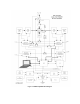
1.3.1 Simplified System Block Diagram Theory
Figure 2-4 is a simplified block diagram of the 2160 DME. The 2170 DME differs only by the addition of
a high power amplifier module in the signal path between the low power amplifier / synthesizer and the
output circulator. The Transponder portion of the DME consists of the Directional Coupler (1A6),
Circulator, Low-Noise Amplifier (LNA), Receiver Transmitter Controller (RTC), and the Low Power
Amplifier / Synthesizer (LPA). Aircraft interrogations are picked up by the antenna and routed through the
Directional Coupler to the Circulator. Additional interrogations from the Monitor/Interrogator are injected
into the Directional Coupler. The responses to these interrogations are sampled by the monitor port within
the antenna and are used to monitor the reply delay and reply efficiency. The Directional Coupler also
provides a sample of the transponder reply to the Monitor/Interrogator. The Monitor/Interrogator also uses
these samples to provide power output measurement.
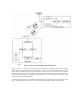
Figure 1-3 System Timing Diagram