
User's Manual


The modulator within the High Power Amplifier module operates in a similar fashion as the modulator in
the low power amplifier above. It receives square-pulse input signals from the RTC, and provides the
collector voltage modulation to achieve the final RF output pulse shaping. The High Power amplifier
provides in excess of 2000 watts peak power across the full DME/TACAN transmitter band with no tuning
required.
The DC/DC converter located within the High Power amplifier provides a constant high voltage power
supply (approximately 53 volts) independent of the DME/TACAN system 48 volt power supply status.
This allows full power operation, even when the system is operating on battery backup and is nearing the
end of the batteries’ useful life. Energy storage capacitance to provide the large peak current requirements
of the RF amplifier stages is also located on the DC/DC converter CCA.
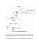
The Monitor portion of the DME consists of two major sections: the Interrogator (for interrogating the
transponder) and the Monitor (to evaluate the reply parameters). Both of these functions are located on the
Monitor/Interrogator/Synthesizer module in the 2160/2170 DME system. The Monitor CCA is actually two
separate printed wiring boards but they are plugged into the other; forming one module. The main board is
dedicated mainly to digital circuitry and is the card-cage support of the module, going from the back plane
to the front panel. The second board is dedicated to Interrogator (RF) circuitry.
Each monitor in the system is capable of monitoring all the critical parameters of two transponders on a
dual DME, and is capable of performing monitor integrity. One monitor interrogator interrogates the
transponders 50 times per second, therefore in a dual system the total rate is 100 interrogations on each
transponder for monitor purposes. The interrogation signals are fed into the transponder via the directional
coupler in the DME/TACAN system, and the transponder replies are routed to the monitor by the forward
coupled transmitter RF signals from the system directional coupler. In dual-equipment stations, the Standby
RF input is obtained from the output of the attenuator load connected to the transfer switch. The monitor
can vary the signal level, the pulse shape and timing and the frequency of the interrogations, so the monitor
sends different interrogations to measure different parameters. In normal mode different interrogations are
mixed together to measure all the critical parameters, if any of these parameters are out of range for an
amount of time, the condition is reported to the LCU using the alarm signals. Upon request from the RMS
other parameters can be measured and reported to the RMS. While a monitor is disabled to interrogate the
transponders (which is half of the time), the monitor uses this time to send certification signals to itself and
verifies that the circuitry and the software are working properly.
The Monitor(s) measure the signals and compare against the operator set limits. If parameters fall outside
the preset limits the alarm indication to the Local Control Unit (LCU) is changed. The LCU examines the
outputs from the Monitor(s) and determine whether to transfer or shutdown the transmitter based on the
present settings such as station bypass, and/or voting logic and whether the equipment is single or dual
transmitter equipment.
The standard PMDT consists of a laptop computer and is the input/output device for controlling and
communicating with the TACAN system. Station control, adjustment and monitoring functions are
available through the computer, and are accessed via a Windows-based operator interface. An external
mouse is supplied with the laptop computer for ease in operation. An optional desktop PC is available as a
substitute for the standard laptop computer. Also, an optional printer is available for use with either the
laptop or desktop PC.
Station security control is provided through a four-level password system. Complete access to the system
for adjustments and measurements is provided at level 3. Modification of non-critical parameters is
available at level 2, and read-only access is available at level 1. Password and account administration is
accomplished at level 4.
All functions available on the local PMDT are available remotely via a modem and dial-up telephone line
to an optional remote laptop or desktop PC running PMDT software.