
Chimney Venting Sizing Handbook

The connector for the single appliance at the lowest level is
sized as an individual vent, terminating at the first tee or
interconnection. For two appliances at the first and succeeding
levels, as in Figure 21, both the connector and common vent
tables are used starting at the lowest level and a total height
up to the next tee or interconnection.
At the second floor, the common vent for the appliance (or
appliances) is considered to terminate at the next
interconnection up, and so on to the highest connected
appliance.
The top floor appliance must have total vent height adequate
for its connector, as well as for the total accumulated input
from below. Because this may necessitate a larger size vent or
greater height above the roof, it may be preferable to use an
individual vent for the top floor appliance. This results in
greater total height for the next floor down and a possible
reduction in vertical vent size.
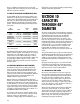
7-10 EXAMPLE OF MULTI-STORY VENT DESIGN
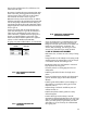
Using the illustration of a multi-story vent, Figure 23, as a
sample design problem, assume first that all four appliances
are attached to a common vertical vent and that input of each
is 100,000 with 5" draft hood outlets. The following table
shows initial calculations.
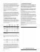
Available Total Common
Total Connector Vent Connector Vent*
Appliance Input Rise Height Size Size
(Self-
1 100,000 12' 12' 5" venting
(lowest) connector)
2 200,000 2' 12' 6" 7"
3 300,000 2' 12' 6" 8"
4 400,000 2' 8' 6" 10"
(top floor)
* Vertical Common Vent
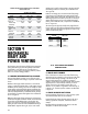
Next, assume that the top floor appliance is individually
vented. For this reason it has been dropped from the revised
table.
(Self-
1 100,000 12' 12' 5" venting
connector)
2 200,000 2' 12' 6" 7"
3 300,000 2' 20' 6" 7"
The revised table shows that the added total height of vent
eliminates a costly size increase and numerous fittings. Had
the total height above the third floor appliance been only 18',
a size increase to 8" would have been required. This also
shows that it may frequently be less expensive to use a slightly
higher vent where the added height permits choice of a
smaller common vent.
7-11 SOME IMPORTANT PRECAUTIONS
A.
Offsets in the common vent are limited to a single offset and can
not exceed 45 degrees from vertical. The horizontal length of the
offset can not exceed 18 in./in. of the common vent diameter in
which the offset is located. The common vent capacity listed in the
common vent tables must be reduced by 20%
B.
Do not assume the total height for any appliance below the top
floor to be the height to the common vent termination. No credit
should be given to any height of common vent above the next
interconnection up.
C.
Use available connector rise effectively, but if it is inadequate,
use the next larger size connector. It is more important to size for
maximum than minimum capacities.
D.
Connector manifolds as illustrated in Figure 21 should be sized
just for their combined input and rise. They do not need to be the
same size as the common vent at the interconnection tee. This entails
either a size increaser going into the tee branch or the use of a tee
with a branch inlet the same size as the manifold.
E.
The vertical body of an interconnection tee serving any level
must be sized on the basis of the total cumulative rated input to the
common vent above it. This means that the connector manifold will
join increasingly larger tees at higher floors.
F.
Be sure that space for the common vent in its air shaft or chase
allows room for fittings, clearance to combustibles, and access for
proper assembly.
G.
Install a Rain Cap immediately to keep debris from entering and
blocking the common vent.
30
FIG. 23 - COMPLETE MULTI-STORY VENT SYSTEM