
Installation Instructions


9. A NOTE ABOUT PRODUCTS OF COMBUSTION FROM PELLET BURNING
APPLIANCES
One of the most common, visible products of combustion from many pellet
burning appliances is a fine, powdery dust which may tend to accumulate
near the outlet of the vent and/ or at the joints within the vent. While this
material is believed to be non-combustible, it should not be permitted to
accumulate within the system since significant accumulation could begin to
affect both the vent system’s ability to function properly and the heating
appliance operation. Accordingly it is recommended that the system be
inspected periodically for the build-up and cleaned if necessary. In order to
help minimize the accumulation of this powder within the system, each vent
section is provided with a hi-temperature fiberglass rope gasket within the
annulus of the female end. This gasket helps minimize air movement through
joints, thereby enhancing the draft through the vent system and minimizing
the powder accumulation.
10. USE OF SEALANTS
(OPTIONAL IN U.S.A. MANDATORY IN CANADA)
Model VP has been listed for use with high temperature silicon sealant applied
to the male end and seams of the vent section just prior to installation. This
sealant in conjunction with the rope gasket, further reduces air infiltration,
minimizing accumulation of the powder.
Vent systems incorporating tee sections, 90 degree elbows and/ or tall heights
are most susceptible to the powder accumulation and should be inspected
and cleaned more frequently. Use only high temperature sealants such as
Dow Corning’s Silastic 732 RTV or Firestop sealant, or comparable, rated for
use at a minimum of 450 degrees F (232deg. C).
NOTE: Model VP Elbows are fully adjustable by means of rotating gores
(sections). Once oriented into the desired position apply sealant at the seams
(pivot points) to seal. Use silicone on the external seams and high temperature
silicone on the internal seams.
11. RULES FOR SAFETY DURING INSTALLATION
A. Wear safety glasses when sawing, nailing, or using other power tools.
B. Wear gloves when handling sheet metal parts with sharp edges.
C. Be sure all electrical tools are properly grounded.
D. Be very careful when cutting openings and working in the area where
electrical wiring is located. Wiring should be secured at least 3” away
from the outer surface of any vent section. If wiring must be relocated,
have this done by a qualified electrician.
E. Ladders, where necessary, should be in good condition and set upon a
firm, level surface.
12. VENTING MORE THAN ONE APPLIANCE
In certain instances more than one gas or oil fired appliance may be connected
to the same vent system. Be sure to follow the appliance manufacturer’s
recommendations and local fire and building code requirements if this is
planned. UNDER NO CIRCUMSTANCES should a pellet burning appliance be
connected into the same vent system as any other type of appliance.
13. SUPPORT
Model VP vent system must be securely supported. Lateral runs are to be
supported at least every 5 feet. When offsets are necessary, adequate
support above and below the offset is required. In addition it is recommended
that each offset elbow be secured with a minimum of two sheet metal screws
at the joint. (See “Vent Section Interconnection”). Vertical runs are normally
supported by the combination Ceiling Support/ Firestop Spacers. Short vertical
vents with less than 6 feet of vertical vent below the flashing may be suspended
from the flashing. In such case, the vent may be supported by the storm collar
resting on the top of the flashing, using 1/4” long sheet metal screws to
attach the storm collar to the vent at the appropriate place. Vents supported
only by the flashing must be guyed above or below the roof to withstand
snow and wind loads. All vents extending above the roof more than 5 feet
must be securely guyed or braced.
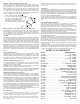
14. GENERAL INSTALLATION INSTRUCTIONS
VENT SECTION INTERCONNECTION
Each flue gas carrying section of Model VP is designed with a male and
female end coupling. To join sections simply push mating ends together until
the locking tabs engage, preventing them from being pulled apart. If additional
securement is desired, one or more, maximum 1/4” long sheet metal
screwsmay be used at the joints. Being careful not to drill through the stainless
steel inner wall of the vent, first drill a 3/32” hole approximately 3/8” above the
line of the joint. Then install the screw(s). NOTE: Anytime sections of Model
VP are supported only from above, the use of these additional screws is
recommended to prevent unintended disengagement of vent sections.
INSTRUCTIONS FOR INSTALLING VENT
Refer to “Common Cosiderations” section for a list of items that should
be taken into consideration before beginning any installation.
Locate appliance per Manufacturers recommendations, making sure to
maintain specified clearances to combustibles.
Attach Pipe Connector (PC) per section on “Pipe Connector” (See Figs
1-4).
If the vent planning was to include a vertical rise, a Tee Section (TS) can
be used to turn the vent vertical (see Figs 2 & 3). Position tee so that it
is vertical, and the cleanout tee cap is at the bottom. Attach tee to vent.
Connect additional vent sections to route the system out of the building.
See “Adjustable Length” section for situations where a non-standard
length of pipe is necessary.
Refer to “Wall Bracket Support” (WB) section for instructions for providing
support for the vent system (See Fig 3).
For vertical penetrations see section on “Vertical Penetrations” for proper
installation (See Figs 1 & 2).
For Horizontal Wall penetrations, see section on “Wall Thimble” for proper
installation (See Figs 3-4).
If a Tee and Tee Support was included in the planning, see section
entitled “Tee and Tee Support” for proper installation (See Fig 3).
When terminating vertically through the roof, see sections on “Roof
Flashing”, “Storm Collar”, & “Vertical Termination Cap” (See Figs 1-3).
When terminating horizontally through a wall, See section on “Horizontal
Termination Cap” (See Fig 4).
See sections 15 & 16 for installation instructions on painting the product
and maintenance requirements.
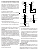
COMMON TYPES OF INSTALLATIONS
Figs. 1 through 4 show four common types of installations of the Model VP
vent system. These figures provide a reference for reviewing common
applications for the various system parts.
NOTE: See Table 1 for Minimum Clearances
FIG. 1
Gas or Pellet
Burning
Appliance
Connector (PC, PCB)
FIG. 2
Connector (PC,
PCB)
Vent Section (Optional)
Gas or Pellet
Burning
Appliance
3" Min. Clearance to
Combustibles
Tee w/ Removable Cap (TS)
Trim Plate (TP)
3" Min. Clearance to
Combustibles
3" Min. Clearance
to Combustibles
Ceiling Support/
Firestop Spacer
Storm Collar (SC)
Vent Cap (VC)
Adjustable
Roof Flashing
(AF)
Ceiling Support/
Firestop Spacer
Trim Plate (TP)
3" Min. Clearance
to Combustibles
Adjustable
Roof Flashing
(AF)
Storm Collar (SC)
Vent Cap (VC)
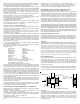
Storm Collar (SC)
Wall Bracket/
Support (WB)
Every 8' Min.
Wall Thimble (WT)
3" Min. Clearance
to Combustibles
Gas or Pellet
Burning
Appliance
Connector (PC, PCB)
Horizontal Clean Out
Tee (TD) (Shown) or
Tee (TS) (Not Shown)
FIG. 3
Tee Support
Brackets (WS)
3" Min. Clearance
to Combustibles
Adjustable
Roof Flashing
(AF)
Vent Cap (VC)
Gas or Pellet
Burning
Appliance
Exterior Shield
(ES) (Optional)
FIG. 4
Horizontal Vent
Termination
Cap (HC)
Connector (PC, P
Wall Thimble (W
T
Min. 6" Length of
Vent, Plus Cap
A.
B.
C.
D.
E.
F.
G.
H.
I.
J.
K.
L.
M.
COMMON CONSIDERATIONS
The following comments apply to all types of installations.
1. Before beginning any installation, select the desired location for the
appliance, being sure to maintain the appliance manufacturer’s specified
minimum clearances. Try to minimize the amount of work by choosing a
location where framing members in the walls and floors will not interfere with
the intended vent location or the required airspace clearances.
2. Where possible, minimize the length and total number and degree of offsets
in your vent system in order to permit the system to vent optimally. Use of too
many offsets may result in poor draft and may affect the performance of the