
Installation Instructions


appliance. If it is necessary to include many offsets and/ or extensive lengths of
vent, consider use of an additional joint sealant. (See “Optional Joint Sealant”) in
order to optimize available draft for the system’s configuration.
3. Throughout these instructions, where preparation of an opening for passage
of Model VP through walls is referenced, we recommend cutting and FRAMING
the opening to the appropriate size. While framing is not necessary in all
cases, it is recommended in order to maintain the integrity of the structure and
provide sufficient anchoring for fasteners, especially where support
assemblies will be installed.
4. Framing of the opening is required for all vertical penetrations where a
firestop is specified, in order to provide adequate fire-stopping.
5. Proper planning for your Model VP vent installation will result in greater
safety, efficiency and convenience, saving time and money.
6. Use ONLY Selkirk Model VP listed parts.
7. DO NOT INSTALL damaged parts.
8. PERMITS are required in most areas. Contact your local building code and/
or fire officials regarding permits, restrictions, and installation inspections in
your area BEFORE you begin your installation.
YOUR SPECIFIC INSTALLATION REQUIREMENTS
Now that you have an overview of the system parts and optional types of
installations, you are ready to plan an installation to meet your specific needs.
We suggest proceeding as follows:
1. Carefully review your options for the installation and select a tentative
location and vent system configuration. This may be similar to one or a
combination of Figs. 1 through 4.
2. Review the appliance installation instructions and determine whether the
location and vent configuration you selected are suitable, convenient and
attainable. Plan to incorporate parts which will facilitate inspection and cleaning.
RULES FOR DISTANCES FROM HORIZONTAL EXIT TERMINATIONS
Before beginning any installation which will result in a vent cap being installed
adjacent to the side of a structure:
1. Check to confirm that local fire and safety codes permit this type of
installation. If so, install per code requirements.
2. In the absence of overriding local requirements, use the following National
Fire Protection Association Standard 211 guidelines for distances from the
exit termination to doors, windows, air inlets, etc.:
Terminations shall be located:
A. Not less than 3 ft. (0.91 m) above any forced air inlet located within 10 ft.
(3m).
4. If you have not already obtained the necessary permits for the installation,
do so before proceeding further.
5. Accumulate all the parts you plan to use along with the tools, equipment
and supplies you may need to complete your work.
These may include:
Eye Protection Hammer
Gloves Assorted Nails
Tape Measure Assorted Wood Screws
Marking Pencil Ladder
Circular Saw Plumb Bob
Screwdriver Razor Knife
Extension Cord Level
Hand Saw Pliers
Square Electric Drill
1/8” or 3/32” drill bit Caulking Gun
“Stud Sensor” or similar device (for locating framing)
Keyhole, Jig, Sabre or Reciprocating Saw
High Temperature silicon sealant
Non-hardening waterproof mastic or caulking
6. If space permits, install the appliance and begin installing the vent system
directly at the appliance flue collar and work toward the termination. If space
does not permit, plan the exact location of your appliance and determine the
exact lengths of system components which will extend between your
appliance flue collar and the wall or ceiling you will penetrate. Begin the
installation of the vent system at this location and work in each direction until
the installation is completed by moving the appliance into position and making
the final connection between the appliance flue collar and the pipe connector.
7. As necessary, refer to these detailed instructions for installation of the
various component parts, being careful to maintain the required clearances
to combustible construction.
8. Upon completion of your installation, check to see the exterior portions of
the vent systems are properly installed and protected from weather. Check to
see that all system components are securely attached and installed in
accordance with the instructions.
9. Install any necessary enclosures in occupied areas and in attics to help
insure that the system is not damaged and that the required airspace clearance
to combustibles is maintained. (See “Enclosures”)
3. After you are satisfied with the location and configuration, plan the exact
layout, identifying all component parts, sizes and dimensions you will need to
complete the installation. Check to insure that you have access to all parts
and accessories you will need.
COMMON VENT SYSTEM PARTS AND THEIR INSTALLATION
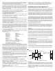
PIPE CONNECTOR (VP-PC, VP-PCB, VP-MFC, VP-APC)
The Pipe Connector is a (“starter section”) fitting used to connect the flue
collar of the appliance to the Model VP vent system. Available in black (PCB)
or unpainted (PC), the connector consists of a single wall cylindrical piece of
stainless steel (which is attached to the flue collar of the appliance) on one
end and a short double wall section of vent on the opposite end which
incorporates a coupling for attachment to other Model VP vent sections. To
install: depending upon the appliance flue collar, insert the Pipe Connector
into or over the appliance flue collar and attach with a minimum of two screws.
A drill with 3/32” bit may be used to drill through the collar and into the connector.
The Adjustable Pipe Connector (APC) and Multi-Function Connector (MFC)
have an adjustable hose clamp on the inlet end to connect to the flue collar
without the use of supplemental screws. The MFC is used to connect to and
increase a 3” diameter flue collar to 4” diameter vent. To install, slide the
inlet end of the APC or MFC over the flue collar. Apply sealant to the flue
collar. Tighten the hose clamp on the connector (sealing and securing) the
APC or MFC to the appliance flue collar.
B. Not less than 4 ft. (1.2m) below, 4 ft. (1.2m) horizontally from, or 1 ft.
(305mm) above any door, window or gravity inlet into any building, and
C. Not less than 2 ft. (0.6m) from adjacent building and not less than 7 ft.
(2.1m) above grade when located adjacent to public walkways.
WALL THIMBLE (VP-WT)
A Wall Thimble (WT) must be used for all through-the-wall installations involving
combustible construction. The standard Wall Thimble is designed to
accommodate wall thicknesses of 4” to 7” while the “Thick Wall” Thimble will
accommodate thicknesses of 6-1/2” to 11-1/2”, and may be installed in direct
contact with combustible framing, insulation and other materials. See Table 1
for Framing requirements.
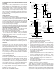
NOTE: The Thimble is shipped in the fully engaged position. Prior to installation,
you must disengage the thimble halves. Disengage by rotating face plates in
a counter clockwise direction (CCW) (unscrew the two halves). See Fig 5.
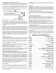
ADJUSTABLE LENGTH (VP-EZAJ12)
Adjustable lengths are designed to be telescoped over a fixed length of vent in
order to create an assembly of specific length. Being an overall length of 12”,
the adjustable length may be used in vertical, horizontal or sloped configurations
but should not be depended upon to support any lengths of pipe beneath.
To install:
Guide the bottom end of the adjustable length down over the upper end of a
straight section in such a manner as to let the inner flue of the adjustable
length slide inside the flue of the fixed section and the outer wall slide down
over the outer wall of the fixed length section. When the desired length is
achieved by this combination, install two 1/4" long screws provided through
pre-punched holes in the outer. Take care not to pierce inner when drilling
outer of VP on lower section to secure the two lengths and prevent slippage.
Note - The adjustable length is commonly used in conjunction with a straight
section and the pipe connector in order to attain a specific length of vent for
adapting the system to a specific placement of the appliance.
WALL THIMBLE
CORRUGATED SHIELD
PREPARED
OPENING
WALL THIMBLE
FACE PLATE
WALL THIMBLE
CORRUGATED SHIELD
NAIL/ SCREW HOLES
ARE PROVIDED AT THE
CORNERS OF THE FACE
PLATES.
WALL THIMBLE
FACE PLATE
WALL THIMBLE INSTALLATION
To Install:
After preparing the proper sized opening (See Table 1), insert the two halves
of the wall thimble from opposite sides of the wall and engage by rotating the
face plates in a clockwise direction (CW) until a snug fit is achieved. If a tee
section with support brackets is to be installed on one side of the wall
penetration, it is recommended to frame the opening. The thimble is now
installed and ready to receive a section of vent. Slide vent through Wall
Thimble (See Fig 5).