
Installation Instructions


TEE SUPPORT (VP-WS)
NOTE: The tee support is optional and should not be installed until the wall
thimble has been completed. IF the tee support is not used, a wall bracket/
support MUST be used within 6” to 12” above the tee and the tee inlet and
outlet joints must be secured with screws as indicated under “Vent Section
Interconnection”.
The tee support kit consists of two (2) symmetrical plate brackets (designed
to accommodate either a 3” or 4” diameter tee), four (4) wood screws (for
attaching the brackets to the wall), and two (2) hex head sheet metal screws
(for attaching the support brackets to the tee).
To Install:
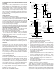
1. Referring to Fig. 6, first draw a pencil line on the outer faceplate of the
thimble, extending horizontally through the center of the hole.
2. Measure down 5-1/2” and draw a second horizontal line. This line, which
is over the center of the lower framing member, will be used to locate the
topmost screws (location “C” in Fig. 6) for the support brackets.
3. Using the left and right upper edge of the hole in the wall thimble face plate
as a starting point, draw vertical lines which extend down to and intersect
the lower, horizontal pencil line.
4. Referring to Fig. 6, orient the support brackets as shown and attach each
to the bottom left and right side of the tee using a hex head screw routed
through the appropriate holes in the support brackets (“A” or “B” from Fig. 6)
and into the 1/8” hole provided in each side of the tee, approximately 1” up
from the bottom. Rotate brackets to the approximate position shown. Engage
screws partially.
5. Insert the pre-selected horizontal section of vent into the inlet of the tee,
pushing it in until the tabs snap lock into place.
6. From the outside insert the open end of the horizontal section (with tee
attached) through the opening in the wall thimble.
7. Orient the support brackets as indicated and situate so that hole “C” in each
support bracket is positioned over the lower horizontal pencil line and the
inside (vertical) edge of each bracket is in approximate alignment with
respective vertical pencil lines extending down from the edges of the hole in
the wall thimble.
8. Once properly situated, secure brackets to wall with four (4) wood screws
(provided) using holes “C” and “D”. Note that the top hole on the flange of
each bracket is not used.
9. Check to see that the correct holes have been used by measuring to verify
that the brackets establish the required airspace between the outside wall
and the tee, then tighten all fasteners.
TEE (VP-TS, VP-TD)
Tee sections are designed for use in changing the orientation of the vent from
horizontal to vertical and to make cleaning of the system easier than if a 90
deg elbow is used. The tee is provided with a cap on the bottom (VP-TS) and
on one side (VP-TD, only) held in place by a friction fit and a screw stop.
To install:
Depending upon the particular installation, the tee is either attached to a tee
support assembly (see Fig. 3) or simply suspended behind the appliance and
supported by a combination of the appliance and support from above (see
Fig.2). In either case, common sections of vent are attached to the tee inlet
and outlet by simply inserting the mating ends until the tabs engage. In Fig 2
type installation and anytime the tee is supported from above, it is recommended
that screws be added to the joints at the inlet and outlet of the tee, in order to
prevent unintended joint separation.
WALL BRACKET/ SUPPORT (VP-WB)
The combination Wall Bracket/ Support is designed to provide both lateral and
vertical support for a vent system which is installed adjacent to a wall. In
addition, properly installed, they provide for the required clearance from the
wall. One VP-WB should be installed 6” to 12” above a tee if the optional tee
support is not used and within the first 8’ if a tee support is used. Additional
VP-WB assemblies should be used at maximum 8’ intervals as the vent system
is routed up the wall. Wall brackets/ supports may be installed as the individual
sections are being installed or they may be pre-installed, centered over a
projected center line of the vent system on the wall of the structure.
To Install:
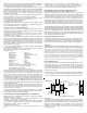
(Refer to Fig. 7) - After properly locating the bracket on the wall, simply attach
the bracket to the wall using the screws provided. A vent section may be
inserted within the collar either before or after attachment to the wall. In either
case, be sure adjacent vent sections are properly joined together, then simply
tighten screw/ nut assembly on collar until collar tightly secures vent section
in place.
Vertical CL of Hole
in Faceplate
NOTE - Bracket Establishes
Required Min 3" Airspace
Clearance to Wall
Wood Screw -
Two Places
Horizontal CL of
Hole in Faceplate
CL of Hole through
Wall for Vent
Outer Plate of Thimble
Assembly
HOLE
A - Use for Attaching 3" Tee
B - Use for Attaching 4" Tee
C & D - Use for Anchoring
Tee Support Brackets to
Wall. Hole "C" Should Line
Up with Center of Bottom
Framing Member.
Clamping Band - Insert
vent Section Within Band
Then Tighten Screw and
Nut to Hold Vent in Place
FIG. 6 WALL BRACKET/ SUPPORT
C
FIG. 5 TEE SUPPORT BRACKET
D
B
A
Tee Support
Brackets
(Each Side)
NOTE - Brackets are
Symmetrical and Designed
to Accommodate 3" or 4"
Vent. Be Sure to Use
Correct Holes to Insure
Proper Spacing From Wall,
and Attachment to Framing
Members.
FIG. 7 WALL BRACKET/SUPPORT
FIG. 6 TEE SUPPORT BRACKET
ATTIC INSULATION SHIELD (AIS)
If the vent system is passing through an opened attic space, it is highly
recommended to either construct an enclosure or install an Attic Insulation
Shield to prevent any debris or blown in insulation from coming in direct
contact with the vent. Install the AIS by slipping it down over the vent
extending through the attic floor and securing to the floor with nails. Extend
the telescoping length to the desired height and secure.
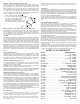
SUPPORT BAND
The Support Band is used to secure the vent pipe to the plate on the CS. After
the CS plate is installed, route the vent pipe up through the hole in the CS plate.
Position the Support Band so that the larger, flanged edge is to the bottom and
slide the support band down over the vent pipe until it is in contact with the CS
plate. Using a screwdriver, tighten the bolt on the Support Band to draw the
ends together and clamp to the vent pipe (See Fig 8).
Ceiling Support
Plate (CS)
Trim Plate
Support Band
Fig 8
VERTICAL PENETRATIONS
A Ceiling Support / Firestop Spacer (CS) must be installed where the vent
passes through a ceiling or floor joist. The CS provides vertical support for
the vent system and maintains the minimum 3” clearance to combustible
materials.
If the location where the vent passes through the ceiling is visible, a Trim Plate
(TP) may be desired in order to provide a finished look to the penetration.
To install:
Determine the location where the vent will pass through the ceiling. Prepare
an opening in the ceiling (See Table 1 for proper framing dimensions). From
the top side of the joist, set the CS plate into the framed opening so that the 4
tabs on the plate extend down into the opening. These tabs help verify that
the minimum clearance to framing is established. Nail the CS plate to the
framing members (See Fig 8). If installing a TP, center the TP on the ceiling
(bottom side) of the opening and secure to the framing members using the
fasteners provided. See Support Band section to complete installation.