
Installation Instructions


MODEL VP SYSTEM PARTS
PART DESCRIPTION
VP-60 .............................................................5’ Length
VP-60B ...............................................5’ Length - Black
VP-36 .............................................................3’ Length
VP-36B ...............................................3’ Length - Black
VP-24 .............................................................2’ Length
VP-12 .............................................................1’ Length
VP-EZAJ12 ...................................1’ Adjustable Length
VP-45EL ...................................................45Deg Elbow
VP-90EL ...................................................90Deg Elbow
VP-AF ....................................Adjustable Roof Flashing
VP-CS ........................Ceiling Support/ Firestop Spacer
VP-TD ........................................Double Tee w/Tee Cap
VP-TS ....................................................Tee w/Tee Cap
VP-SC ........................................................Storm Collar
VP-TF ......................................Tall Cone Roof Flashing
VP-WB ........................................Wall Bracket/ Support
VP-WS .......................................................Tee Support
VP-HC ................................Horizontal Termination Cap
VP-VC .....................................Vertical Termination Cap
VP-WT ......................................................Wall Thimble
VP-WTT ..........................................Thick Wall Thimble
VP-ES ....................................................Exterior Shield
VP-PC ...................................................Pipe Connector
VP-PCB ....................................Pipe Connector - Black
VP-A6 ..................................................MCS Adapter - 6”
VP-A8 .................................................MCS Adapter - 8”
3VP-I4 ................................................Increaser - 3” to 4”
VP-TP ...............................................Trim Plate - Black
VP-EC ...............................................Exit Cap
16. MAINTENANCE REQUIREMENTS
Refer to the appliance manufacturer’s maintenance instructions for
recommendations relative to required maintenance of your appliance.
-Model VP vent system requires periodic inspection and cleaning with an
appropriately sized brush which will not scratch the inside surface of the
flue. DO NOT USE chemical cleaners to clean your venting system.
-Frequency of necessary vent system cleaning will vary with the appliance,
vent system configuration and climate. Certain pellet burning appliances or
pelletized fuels may give off more fine dust than others.
-In any case it is recommended that the complete assembly be inspected and
cleaned (if any buildup has occurred) at the beginning of each heating season
and at least monthly thereafter.
-TO INSPECT AND CLEAN . . . Remove the termination cap by removing any
screws, then rotating and pulling until it disengages. Remove the tee cap(s)
by removing the stop screw and pulling the cap off. Inspect system. If
necessary clean by running a brush through the system several times in
each direction. NOTE - Be sure that tee and termination caps are reinstalled
and secured when Inspection/ Cleaning is completed and before the system
is put back in use.
-IN CASE OF FIRE . . .If a fire occurred within the vent system, de-energize
the appliance, close all draft controls, evacuate the premises and call the Fire
Department. Do not use the appliance or vent system until they have been
inspected by a qualified individual and declared suitable for further use.
15. PAINTING
To prolong the life and appearance of the outer casing and other parts of the
Selkirk Model VP Vent System located outdoors, use proper painting procedure
at time of installation. Remove oil and dirt with a solvent. Paint first with a good
quality zinc primer or other primer recommended for use on galvanized steel.
Next apply an appropriate finish coat. Similar considerations apply for painting of
internal components, for aesthetic purposes.
Ordinary house paints applied directly to outer casing may not adhere well
and do not prevent under film corrosion which leads to paint loosening and
peeling. Be sure to use a good primer undercoat and an appropriate finish
coat.
To Install: Slide the Exit Cone Cap onto the section of vent extending out
from the wall until the lances on the cap engage within the groove on the
end of the pipe.
EXIT CAP (VP-EC)
As an alternate to the Horizontal Termination, an Exit Cone Cap is available.
This cap is designed to direct flue gases perpendicular to the wall and to
increase their velocity, projecting them further away from the building.
Note: When using the Exit Cone Cap, make sure it will be installed so that
the hot flue gases do not overheat any of the surrounding area or pose any
burn hazard to humans.
HORIZONTAL TERMINATION CAP (VP-HC)
The horizontal termination cap is designed specifically for use on installations
in which the vent terminates in a horizontal orientation on the outside of a
structure. See Fig. 4 and the section which discusses this type installation.
To Install: Slide the cap onto the (minimum 6”) section of vent extending out
from the wall until the tabs engage. Orient the cap so that the shielded sides
of the assembly are on top and bottom while the two outlet openings are
facing the sides. NOTE - In order for the cap to provide the intended protection
and vent the products of combustion properly, the cap must be installed in the
above described orientation. Once installed as intended, carefully drill 3/32”
holes in the left and right side of the cap’s collar and through (only) the outer
wall of the vent section. Drive a 1/4” long sheet metal screw in each hole to
prevent the cap from being removed or rotated unintentionally.
The above part descriptions and installation instructions should be referenced
as you plan and install your particular installation.
VERTICAL TERMINATION CAP (VP-VC)
The VP-VC is intended for use in all installations in which the vent terminates
in a vertical orientation. The cap provides necessary protection of the vent
system from rain and other elements.
To Install: Simply push the cap down onto the top section of vent until the
spring clips engage. No additional attachment is required.
TERMINATION HEIGHT ABOVE ROOF - The termination of Model VP should be
located a sufficient distance from the roof so that the discharge opening is at
least two (2) feet above the roof surface, or nearby structure.
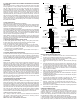
ROOF FLASHINGS - TALL CONE (VP-TF), ADJUSTABLE (VP-AF)
Roof flashings are used to provide a transition at the roof through which the
vent will pass and to protect the interior of the structure from weather. The
VP-TF is intended for use only on flat roofs while the VP-AF is designed for
use on roofs having a slope of 0/12 (flat) to 6/12. Flashings are always used
in conjunction with a storm collar (VP-SC).
To install:
After determining the exact location where the vent assembly will penetrate
the roof, cut hole which will provide the required minimum airspace to roof
and/ or framing members. After adding vent sections so that the assembly
extends up through and is centered within the prepared opening, slide the
flashing down over the assembly. On a sloped roof, insert the upper edge
and sides of flashing under the roofing material using non-hardening,
waterproof mastic around the perimeter of the bottom side and nail to the roof
along the upper edge. Do not nail the lower edge, but be sure to include
mastic along its bottom edge. On a flat roof, use mastic or caulking around the
perimeter of the bottom side, set on roof and nail or screw at the corners.
Apply mastic over the heads of the fasteners and an additional bead around
the edge.
STORM COLLAR (VP-SC)
The storm collar is used at the top of each flashing to assist in shedding
water from the assembly. To Install: Prior to installing the cap and after
installing the flashing, install the storm collar by sliding it down over the upper
vent section until it rests directly upon the flashing. Apply non-hardening
waterproof mastic along the line where the storm collar meets the vent.
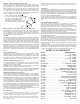
ELBOWS - 45 DEG (VP-45EL), 90 DEG (VP-90EL)
The sections (gores) of adjustable 45 (max) and 90 (max) elbows turn to
achieve various angles. These are used to accommodate unusual offsets
and configurations. Start by turning the elbow sections until the desired
angle is reached. Once in position, seal the seams (rotating points). Clear,
grey or black silicone can be used on the seams of the outer jacket (See Fig
9). However, use high temperature silicone on the seams of the inner liner.
The elbows are designed with the same end couplings as the straight sections
in order to facilitate their use anywhere in the system.
Model VP Elbows are fully adjustable
by means of rotating gores (sections).
Once oriented into the desired position,
apply silicone to the seams to seal.
Be sure high temperature silicone is used
when sealing the seams of the inner liner.
Fig 9