LoRa EdgeTM Tracker Reference Design Evaluation User Guide (“User Guide”) July 2020
Table of Contents Welcome! ........................................................................................................................................................... 4 What is in the Kit? .............................................................................................................................................. 4 System Overview ...............................................................................................................................................
Product & Safety Instructions ...................................................................................................................... 32 Warnings ...................................................................................................................................................... 32 Notices .........................................................................................................................................................
LoRa EdgeTM Tracker Reference Design Evaluation Kit Welcome Welcome! The LoRa EdgeTM Tracker Reference Design Evaluation Kit (“Kit”) is a portable reference Kit designed to introduce the LR1110 tracking capabilities with LoRa Cloud Services integrated with premium and showcase LoRaWAN network coverage around a building or site and to accelerate solution development for a wide range of stakeholders.
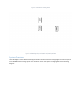
Figure 1: LR1110-based Tracking Device ANT1 ANT3 ANT2 Figure 2: LoRaWAN gateway with 3G/4G LTE (Cellular) backhaul System Overview The LoRa EdgeTM Tracker Reference Design Evaluation kit demonstrates and highlights the various aspects of a LoRaWAN asset tracking system. The elements used in this system are highlighted in the following diagram.
The data flow proceeds from the LR1110 Tracking devices through the provided gateway in the kit to the Actility LoRaWAN network server. This server manages the LoRaWAN network Join process through the LoRa Cloud™ Device Join Server and once the LR1110 devices have joined the network, the Actility LoRaWAN server is the conduit for data to and from the application service hosted by Tago.io. The Tago.
Figure 3: Gateway connections About the Gateway The ODU gateway is an 8-channel LoRaWAN-compliant gateway with external antennas. This gateway has the following features: Support for LoRa Basics™ Station Gateway ping Support for LoRaWAN 1.0.
Gateway Setup To set up the gateway, follow the steps below. Note: Do not connect power until all antenna connections are complete.
Step 3: Connect the Ethernet cable to the gateway Figure 6: Connecting the Ethernet cable to the gateway Step 4: Connect the Ethernet cable to the power brick.
Step 5: Connect the Cellular antenna (ANT2) Figure 8: Connecting the Cellular antenna to the gateway Step 6: (Optional) Connect the GPS cable to the GPS Antenna Figure 9: Connecting the GPS cable to the GPS antenna
Step 7: (Optional) Connect the GPS cable to the gateway (ANT1) Figure 10: Connecting the GPS cable to the gateway Step 8: Connect the power brick to a power source.
Step 9: Verify and test. Check the LED on the power brick. The LED will be green when power is supplied to the gateway. Figure 12: Green LED on Power Brick Means Gateway is Powered Gateway SIM and Data Connectivity The gateway is provided with a SIM card for cellular backhaul. This includes 1GB of free data service, which should be adequate for about one year of operation. If you need more data, you will need to sign up for a cellular service plan and provide a replacement SIM card.
Getting the Kit Online There are a few steps involved in getting your LR1110 Trackers online for the first time. The process of setting up the devices will be illustrative of the overall setup and system configuration. By following the steps outlined below, you should be up-and-running in less than 30 minutes. Creating the LoRa Cloud™ Portal Account Before a LR1110 Tracker device can be claimed however, you first must have an account on the LoRa Cloud™.
Enter the EUI and the PIN (Claim) retrieved from the modem and press “Claim Device”. If the EUI and PIN are matched in the LoRa Cloud™ Device Claim system, it will be added to your available devices. You could have also used the “Bulk Upload(CSV)” option to provide the LoRa Cloud™ Device Join service with the information that you entered on the form; however, it would need to be in a file with the provided format on that page.
The purpose of mapping the Registered Network Server to a specific Application Owner is so that specific parameters can be setup for handling data when operating with that LNS. There are three common settings for each Application definition: name, wrapkey and nslist. The name is an arbitrary string to represent the application.
Selecting the Actility Network Server on the LoRa Cloud™ Device Join Server Once the owner has been established, you must select the Network Server on the LoRa Cloud™ Device Join Server. To do this, go to the “NETWORK SERVERS” link on the left and on the Network Servers page select the Actility ThingsPark Wireless DEV1 and hit “ADD”. Currently the “Owner Context” for these devices is not defined.
To create an owner that can use the DAS, first login to your LoRa Cloud™ account (https://www.loracloud.com) and select the “LoRa Cloud™ Device and Application Services”. There is a “Manage Owners” page accessible from the main DAS page. On the “Manage Owners” page you will create an owner or owners and then set the currently active owner. The active owner is where you will define tokens with the properties you need.
locations can be computed every month. Paid plan quotas range from the hundreds of thousands to many millions. See the link https://www.loracloud.com/portal/geolocation/subscription_management for further information on pricing plans. Getting Localization Results To utilize the LoRa Cloud™ Geolocation API, the LR1110 Tracker will provide scan information for LoRa® signals, Wi-Fi scan or GNSS measurements.
Setup and Operation of the LR1110 Trackers The LR1110 Trackers are shipped with batteries outside of the unit so that they will not transmit while in transport. This section will provide the instructions for the setup of the device, pairing it with its initialization phone application and connecting to the services it supports.
Make sure that the batteries are oriented in the correct direction lining up the “+” and “-“ symbols on the device: Place the bottom plate back on the device and secure all four screws completely.
Then place the flat side of the magnet directly against the device. This should cause a RED LED to light up. At this point, the LR1110 Tracker is in pairing mode.
This should quickly pair the phone to the LR1110 Tracker showing the following:
Setting up the Application to Retrieve Aiding In order to achieve aided GNSS acquisition, you need to bridge from the device to the LoRa Cloud™ DAS. Upon launching, you will be asked for permissions for photos and media (please allow). Setting the LoRa Edge Tracker….
Select a connected device
Create a QR code for the DAS token: 1) 2) 3) 4) 5) Login to the LoRa Cloud™ website (https://loracloud.com) Go to LoRa Cloud™ Device & Application Service>Manage Tokens Copy the value of your created token Create a QR code with https://www.qrstuff.com/ (or similar) On the mobile application, when asked for LoRa Cloud Authentication, allow the app to take a picture of your created QR code Application Features and Functions There are a number of features and functions of the mobile application.
If you want to use GNSS estimation for the LR1110 Tracker, it must be enabled by checking the “GNSS feature” box on the application (you might need to scroll down past the “LoRaWAN” section): You can set the device to receive aiding information at your approximate location. Note that the input will take “+” for positive latitude (North) and “-“ for negative latitude (South). Similarly for positive longitude use “+” for positive (East) and “-“ for negative (West).
latitude or longitude respectively, even if you are at Southern latitudes or Western longitudes. The “-“ sign however, takes precedent.
You can also change a variety of Wi-Fi scan settings with the application including, the number of retries, the maximum number of returned APs, the Wi-Fi type and the Wi-Fi timeout in milliseconds. In the “Miscellaneous” section of the application you can control a variety of features including “Airplane Mode”, Use accelerometer, the TX regular and Low duty cycles and a full reset of the device.
Add Devices and Map Location Once the gateway and tracking devices are turned on, when you connect to the online web interface the device should report be visible on the Device Settings page, and should show an updated time, similar to the example shown in Figure 13. Figure 13 – Devices and Gateway Reporting Example Using the Web Dashboard To begin, log in by scanning the QR code below or, using your web browser (Chrome preferred), navigate to https://lordevelopers.semtech.
Device Tracking View At the center of the Device Tracking view is a map showing the locations of the enabled tracking devices. To the right of the map, in the Trackers pane, is a list of the available trackers. To turn the display of a given tracker on or off, toggle the “eye” icon ( “target” icon ( ). To zoom in on the latest position for a given tracker, click the ). Figure 15. Device Tracking view Below the list of trackers is the Tracking Period pane.
Figure 16. Device Settings view Problems/Concerns Direct any problems or concerns to TrackerSupport@XYZ.com.
Important Information: Warranty Disclaimer The Kits are supplied for demonstration purposes only. Your use of the Kits for any purposes (e.g., commercial) is unauthorized by Semtech and at your own risk. THE KITS ARE PROVIDED "AS IS" AND WITHOUT WARRANTY OF ANY KIND EXPRESSED OR IMPLIED. SEMTECH EXPRESSLY DISCLAIMS ALL WARRANTIES, EXPRESSED, IMPLIED OR OTHERWISE, INCLUDING WITHOUT LIMITATION, WARRANTY OF MERCHANTABILITY, FITNESS FOR A PARTICULAR PURPOSE, AND NON-INFRINGEMENT OF INTELLECTUAL PROPERTY RIGHTS.
Notices Avoid exposing your sensors or batteries to very cold or very hot temperatures. Low or high temperature conditions may temporarily shorten the battery life or cause the sensors to temporarily stop working. Take care in setting up the gateway and other hardware. Follow all installation instructions in the User Guide. Failure to do so may result in injury. Do not install hardware equipment while standing in water or with wet hands. Failure to do so can result in electric shock or death.
FCC Caution: Any changes or modifications not expressly approved by the party responsible for compliance could void the user's authority to operate this equipment. This device complies with Part 15 of the FCC Rules. Operation is subject to the following two conditions: (1) This device may not cause harmful interference, and (2) this device must accept any interference received, including interference that may cause undesired operation.