DirectPort Product Family Multi-port Serial Cards Hardware User Guide Rev 1.0.0 Sena Technologies, Inc. www.sena.
Copyright Copyright 2010, Sena Technologies, Inc. All rights reserved. Sena Technologies reserves the right to make changes and improvements to its product without providing notice. Trademark Windows® is a registered trademark of Microsoft Corporation. Notice to Users When a system failure may cause serious consequences, protecting life and property against such consequences with a backup system or safety device is essential.
Contents 1 Introduction 5 1.1 About This Document 5 1.2 DirectPort Product Family 5 1.3 Product Specifications 2 DirectPort UPCI2 6 7 2.1 DB9 Pin Assignments 7 2.2 Cabling 7 2.2.1 Connecting Terminal 2.2.2 Connecting Modem 3 DirectPort UPCI2B 7 7 8 3.1 DB9 Pin Assignments 8 3.2 Jumper Settings 8 3.2.1 RS422/RS485 Selection 8 3.2.2 Termination Resistance Selection 9 3.2.3 Slew Rate Limit Ability 3.3 Cabling 9 10 3.3.1 RS422 Point-to-Point Connection 10 3.3.
6 DirectPort UPCI8SP 15 6.2 Cabling 15 6.2.1 Connecting Terminal 6.2.2 Connecting Modem 7 DirectPort UPCI8BSP 15 15 16 7.1 DB9 Pin Assignments 16 7.2 Jumper Settings 16 7.2.1 RS422/RS485 Selection 16 7.2.2 Termination Resistance Selection 17 7.2.3 Slew Rate Limit Ability 17 7.3 Cabling 18 7.3.1 RS422 Point-to-Point Connection 18 7.3.2 RS422 Multi-Drop Connection 18 7.3.3 RS485 Connection 8 DirectPort UPCI8LP 18 19 8.1 DB9 Pin Assignments 19 8.2 Cabling 19 8.2.
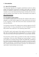
1 Introduction 1.1 About This Document This document describes the hardware specifications and the cabling guide of the DirectPort universal PCI multiport serial cards. For software and driver installation, please refer to the Software User Guide in the CD included. You can also download documents including this document and the Software User Guide from Sena Technologies home page at http://www.sena.com 1.
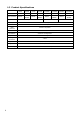
1.3 Product Specifications UPCI2 UPCI2B UPCI4 UPCI4B UPCI8SP UPCI8BSP UPCI8LP Serial Ports 2 2 4 4 8 8 8 8 Line Interface RS232 RS422/ RS485 RS232 RS422/ RS485 RS232 RS422/ RS485 RS232 RS422/ RS485 Form Factor 6 Low Profile/Standard Profile Standard Profile Serial Speed Up to 921.6 Kbps BUS Interface PCI Local Bus Spec 2.
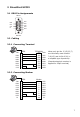
2 DirectPort UPCI2 2.1 DB9 Pin Assignments RS232 DSR 6 RTS 7 CTS 8 RI 9 1 DCD 2 RXD 3 TXD 4 DTR 5 GND DB9 Male 2.2 Cabling 2.2.1 Connecting Terminal TXD RXD DTR DSR GND DCD RTS CTS 3 2 4 6 5 1 7 8 DB9 TERMINAL 2(3) 3(2) 6(6) 4(20) 5(7) 7(4) 6(5) 1(8) RXD TXD DSR DTR GND RTS CTS DCD When only pin No. 2,3,5(2,3,7) are informally used connect 7-8(4-5) and 4-6(4-8-20) in a loopback type repectively. (Parenthesized pin number is applied for 25pin terminal) 2.2.
3 DirectPort UPCI2B 3.1 DB9 Pin Assignments RS485 6 TRXD- 7 8 9 RS422 1 2 3 TRXD+ RXD- 6 TXD- 7 8 4 5 9 GND DB9 Male 8 INTERFACE INTERFACE 3.2.1 RS422/RS485 Selection 485: Set RS485 Interface 2 RXD+ 3 TXD+ 4 5 DB9 Male 3.
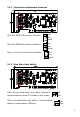
3.2.2 Termination Resistance Selection 422: Set RS422 Termination Resistor 422 485 NONE 485: Set RS485 Termination Resistor 422 485 NONE None: Do not set Termination Resistor 422 485 NONE 3.2.3 Slew Rate Limit Ability 10M: Not use Slew Rate Limit ability. Maximum 10M communication speed 921.6Kbps in this mode. 250K 250K: Use Slew Rate Limit ability. Communication 10M speed is limited under 250Kbps.
Slew Rate Limit reduces reflected waves emitting from ends of communication cables and speeds up slew-rate driver that restrains EMP electromagnetic waves thereby enabling communication with no data errors. But communication speed is limited in this mode 3.3 Cabling 3.3.1 RS422 Point-to-Point Connection RXD+ TXDRXD- 3 2 2 3 7 6 6 7 RXD+ TXD+ RXD- Terminal Host TXD+ TXD- 3.3.
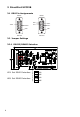
4 DirectPort UPCI4 4.1 DB9 Pin Assignments RS232 DSR 6 RTS 7 CTS 8 RI 9 1 DCD 2 RXD 3 TXD 4 DTR 5 GND DB9 Male 4.2 Cabling 4.2.1 Connecting Terminal TXD RXD DTR DSR GND DCD RTS CTS 3 2 4 6 5 1 7 8 DB9 TERMINAL 2(3) 3(2) 6(6) 4(20) 5(7) 7(4) 6(5) 1(8) RXD TXD DSR DTR GND RTS CTS DCD When only pin No. 2,3,5(2,3,7) are informally used connect 7-8(4-5) and 4-6(4-8-20) in a loopback type repectively. (Parenthesized pin number is applied for 25pin terminal) 4.2.
5 DirectPort UPCI4B 5.1 DB9 Pin Assignments RS485 6 TRXD- 7 8 9 RS422 1 2 3 TRXD+ RXD- 6 TXD- 7 8 4 5 9 GND DB9 Male 12 INTERFACE INTERFACE 5.2.1 RS422/RS485 Selection 485: Set RS485 Interface 2 RXD+ 3 TXD+ 4 5 DB9 Male 5.
5.2.2 Termination Resistance Selection 422: Set RS422 Termination Resistor 422 485 NONE 485: Set RS485 Termination Resistor 422 485 NONE None: Do not set Termination Resistor 422 485 NONE 5.2.3 Slew Rate Limit Ability 10M: Not use Slew Rate Limit ability. Maximum 10M communication speed 921.6Kbps in this mode. 250K 250K: Use Slew Rate Limit ability. Communication 10M speed is limited under 250Kbps.
Slew Rate Limit reduces reflected waves emitting from ends of communication cables and speeds up slew-rate driver that restrains EMP electromagnetic waves thereby enabling communication with no data errors. But communication speed is limited in this mode 5.3 Cabling 5.3.1 RS422 Point-to-Point Connection RXD+ TXDRXD- 3 2 2 3 7 6 6 7 RXD+ TXD+ RXD- Terminal Host TXD+ TXD- 5.3.
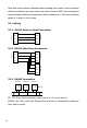
6 DirectPort UPCI8SP 6.1 DB9 Pin Assignments RS232 DSR 6 RTS 7 CTS 8 RI 9 1 DCD 2 RXD 3 TXD 4 DTR 5 GND DB9 Male 6.2 Cabling 6.2.1 Connecting Terminal TXD RXD DTR DSR GND DCD RTS CTS 3 2 4 6 5 1 7 8 DB9 TERMINAL 2(3) 3(2) 6(6) 4(20) 5(7) 7(4) 6(5) 1(8) RXD TXD DSR DTR GND RTS CTS DCD When only pin No. 2,3,5(2,3,7) are informally used connect 7-8(4-5) and 4-6(4-8-20) in a loopback type repectively. (Parenthesized pin number is applied for 25pin terminal) 6.2.
7 DirectPort UPCI8BSP 7.1 DB9 Pin Assignments RS485 6 TRXD- 7 8 9 RS422 1 2 3 TRXD+ RXD- 6 TXD- 7 8 4 5 9 GND DB9 Male 16 INTERFACE INTERFACE 7.2.1 RS422/RS485 Selection 485: Set RS485 Interface 2 RXD+ 3 TXD+ 4 5 DB9 Male 7.
7.2.2 Termination Resistance Selection 422: Set RS422 Termination Resistor 422 485 NONE 485: Set RS485 Termination Resistor 422 485 NONE None: Do not set Termination Resistor 422 485 NONE 7.2.3 Slew Rate Limit Ability 10M: Not use Slew Rate Limit ability. Maximum 10M communication speed 921.6Kbps in this mode. 250K 250K: Use Slew Rate Limit ability. Communication 10M speed is limited under 250Kbps.
Slew Rate Limit reduces reflected waves emitting from ends of communication cables and speeds up slew-rate driver that restrains EMP electromagnetic waves thereby enabling communication with no data errors. But communication speed is limited in this mode 7.3 Cabling 7.3.1 RS422 Point-to-Point Connection RXD+ TXDRXD- 3 2 2 3 7 6 6 7 RXD+ TXD+ RXD- Terminal Host TXD+ TXD- 7.3.
8 DirectPort UPCI8LP 8.1 DB9 Pin Assignments RS232 DSR 6 RTS 7 CTS 8 RI 9 1 DCD 2 RXD 3 TXD 4 DTR 5 GND DB9 Male 8.2 Cabling 8.2.1 Connecting Terminal TXD RXD DTR DSR GND DCD RTS CTS 3 2 4 6 5 1 7 8 DB9 TERMINAL 2(3) 3(2) 6(6) 4(20) 5(7) 7(4) 6(5) 1(8) RXD TXD DSR DTR GND RTS CTS DCD When only pin No. 2,3,5(2,3,7) are informally used connect 7-8(4-5) and 4-6(4-8-20) in a loopback type repectively. (Parenthesized pin number is applied for 25pin terminal) 8.2.
9 DirectPort UPCI8BLP 9.1 DB9 Pin Assignments RS485 6 TRXD- 7 8 9 RS422 1 2 3 TRXD+ RXD- 6 TXD- 7 8 4 5 9 GND DB9 Male 20 INTERFACE INTERFACE 9.2.1 RS422/RS485 Selection 485: Set RS485 Interface 2 RXD+ 3 TXD+ 4 5 DB9 Male 9.
9.2.2 Termination Resistance Selection 422: Set RS422 Termination Resistor 422 485 NONE 485: Set RS485 Termination Resistor 422 485 NONE None: Do not set Termination Resistor 422 485 NONE 9.2.3 Slew Rate Limit Ability 10M: Not use Slew Rate Limit ability. Maximum 10M communication speed 921.6Kbps in this mode. 250K 250K: Use Slew Rate Limit ability. Communication 10M speed is limited under 250Kbps.
Slew Rate Limit reduces reflected waves emitting from ends of communication cables and speeds up slew-rate driver that restrains EMP electromagnetic waves thereby enabling communication with no data errors. But communication speed is limited in this mode 9.3 Cabling 9.3.1 RS422 Point-to-Point Connection RXD+ TXDRXD- 3 2 2 3 7 6 6 7 RXD+ TXD+ RXD- Terminal Host TXD+ TXD- 9.3.
10 Regulatory Information 10.1 FCC Compliance Statement This equipment has been tested and found to comply with the limits for a Class A digital device, pursuant to part 15 of the FCC Rules. These limits are designed to provide reasonable protection against harmful interference when the equipment is operated in a commercial environment.
Sena Technologies, Inc. www.sena.