HD132x Series User Manual Version 1.
HD132x Series User Manual Version 1.1 Last revised on May 28, 2001 Printed in Korea Copyright Copyright 2001, Sena Technologies, Inc. All rights reserved. Sena Technologies is having the right to make changes and improvements to its product without providing notice. Trademark HelloDevice™ is a trademark of Sena Technologies, Inc. Windows® is a registered trademark of Microsoft Corporation. Ethernet® is a registered trademark of XEROX Corporation.
Contents 1. Before You Start...................................................................................................................................4 2. Overview ..............................................................................................................................................5 3. Product Specifications .........................................................................................................................6 3.1 HD1320E / HD1320 .........................
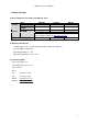
HD132x Series User Manual 1. Before You Start u Items supplied in each model of the HD132x Series Hardware Software Items Product Type Power Supply Adaptor RS232 Cable CD-ROM HD1320E External Box ¦ HD1320 PCB Board - HD1321 PCB Board - ¦ ¦ Download the latest version of HelloDevice Utility Software and Demo Sample Programs at http://www.sena.com. User Manual Hardcopy ¦ - - u Operating Environment - Voltage Supply = 7.5V ~ 9V DC (HD1320/1320E), 5V DC ±10% (HD1321) - Current Supply = 150mA min.
HD132x Series User Manual 2. Overview HD132x Series is an RS232 to TCP/IP protocol converter, which enables data communication between the device and the user, over the Internet as client and/or server. With HD132x Series, users can easily send data to the device and/or receive data from the device over the Internet.
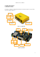
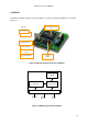
HD132x Series User Manual 3. Product Specifications 3.1 HD1320E / HD1320 The hardware configuration of HD1320E and HD1320 are shown below in Figure 3.1(a), (b), and, the system block diagram in Figure 3.2. Status LEDS Power Collision Rx Tx RJ-45 Connector To Ethernet Serial Connector (RS-232) Power Connection ( 7.5V ~ 9V DC ) Figure 3.
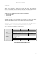
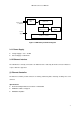
HD132x Series User Manual RJ45 connector to Ethernet 10 Base-T filter Ethernet controller (10 Base-T) Sx52BD microprocessor 32 KB RAM Power supply 1 serial port RS232 Figure 3.2 HD1320 System Block Diagram 3.1.1 Power Supply l l Voltage Supply = 7.5V ~ 9V DC Current Supply = 150mA min. 3.1.2 Ethernet Interface The HelloDevice is directly connected to an Ethernet hub or switch by the RJ45 connector. Distances of up to 100m are supported.
HD132x Series User Manual (2) RJ45 Connector l Shielded Connector compliant with AT&T258 specifications 1=Tx+ 8=NC 2=Tx- 7=NC 3=Rx+ 4=NC Pin No. 1 2 3 4 5 6 7 8 Description Tx+ TxRx+ Not used Not used RxNot used Not used Wire Color White with orange Orange White with green Blue White with blue Green White with brown Brown 6=Rx- 5=NC Figure 3.3 RJ45 Connector (3) Status Indicator LED's There are four status indicator LED’s to indicate the following: § (See Figure 3.
HD132x Series User Manual 3.1.3 RS232 Communication Interface l DB9 Connector for RS232 communication l Serial speeds 150bps ~ 115Kbps 3=TxD 2=RxD 4=NC 1=NC 5=GND 6=NC 9=NC 7=RTS Pin No.
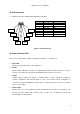
HD132x Series User Manual 3.2 HD1321 The HD1321 hardware structure is shown in Figure 3.5 and the system block diagram is as shown in Figure 3.6. Rear side 10BaseT Ethernet Chip microprocessor UART External interface Ethernet interface Power Connection ( 5V DC ) 32 KB SRAM TTL RS232 interface Figure 3.5 HD1321 Hardware Structure and Names 32 KB SRAM Ethernet controller (10 Base-T) Sx52BD microprocessor External Interface Ethernet RS232 Interface Power supply Figure 3.
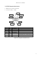
HD132x Series User Manual 3.2.1 Power Supply l l Voltage Supply = 5V DC ±10% Current Supply = 150mA min. 3.2.2 External Interface There is a total of 20 pins in the connector JP1 and JP2 in HD1321 to interface microprocessor, Ethernet controller and UART with the user device. (See Table 3.1 and Figure 3.
HD132x Series User Manual GND Vcc Reset NC LED2 DSR LED1 LED0 TPOut- TPOut+ 1 2 3 4 5 6 7 8 9 10 1 2 3 4 5 6 7 8 9 10 CTR DTR RTS RxD TPIn+ TPIn- Vcc NC GND JP1 JP2 TxD Figure 3.
HD132x Series User Manual 3.3 Firmware Structure The HelloDevice Firmware resides in the program memory of microprocessor. The firmware includes a TCP/IP stack conforming to the Open System Interconnection (OSI) requirements for an Internet connection, and the serial communications interface for connection to the user device. Layer HelloDevice Support 7 Application 6 Presentation 5 Session 4 Transport 3 Network 2 Data link IP / ICMP 1 Physical layer Ethernet (IEEE802.
HD132x Series User Manual 4. Setting Up Your HelloDevice The HelloDevice is installed in a following order: 1. Connect the HelloDevice to the power supply and Ethernet 2. Install the HelloDevice Utility Software on your PC 3. Assign an IP address of the HelloDevice 4. Set parameters of the HelloDevice 4.1 Connecting Hardware 4.1.1 Connecting HD1320 / 1320E Since the hardware architecture of HD1320E and HD1320 is identical to each other, so is the setup process.
HD132x Series User Manual Ethernet backbone 110/220 V 7.5V DC Pwer HD1320E Ethernet Cable Hub & Switch Figure 4.2. Connection of HD1320E and Ethernet Cable (3) Check to see if the Tx LED in Status LED's blinks every second. Tx LED blinks periodically when an IP address is not assigned, which is normal at this stage. (See [Status LED's] in Figure 3.1).
HD132x Series User Manual 4.1.2. Connecting HD1321 HD1321 is interfaced with the user device through the DIP type connector, and the power supply and RJ45 connector are implemented on the user device. Figure 4.6 shows the pin assignment of the connector and the interface circuit diagram. Figure 4.
HD132x Series User Manual 4.2 Installing HelloDevice Utility Software Run setup.exe in the HelloDevice CD-ROM from the PC that is connected to the network. Setup132x.exe runs on Microsoft Windows 95/98/ME/NT/2000. The initial screen of setup132x.exe is shown below in Figure 4.1 Figure 4.
HD132x Series User Manual Figure 4.5 Initial Screen of [Custom Setup] When the installation has been completed, the HelloDevice Utility Software shortcuts are created on your desktop and program menu. Click on the icon and if you see the windows screen as in Figure 4.6, then the installation has been successfully completed. Figure 4.
HD132x Series User Manual 4.3 Managing an IP address of the HelloDevice Now we have the HelloDevice physically connected the network and the HelloDevice Utility Software installed on your PC, We will go through the rest of the setup process with the HelloDevice Utility Software in the following order: 1. Assign an IP address of the HelloDevice 2. Set password 3. Set network Mode parameters 4.
HD132x Series User Manual address is labeled on NIC (Network Interface Card) of the HelloDevice, and the user specifies an IP address. Consult your network manager for correct network information. Now, let’s assign an IP address with the HelloDevice Utility Software step-by-step. (1) Launch the HelloDevice Utility Software and select [IP Address] tab.
HD132x Series User Manual Figure 4.8 [Server Setting] Window (3) Press [Add] button and enter the DHCP database record. Figure 4.9 [Add] Window Since the HelloDevice is connected to the Internet through Ethernet, [H/W Address Type] and [H/W Address Length] should always be 1 and 6, respectively. Enter [Client IP Address] and [Client H/W Address]. [Client IP Address] and [Client H/W Address] are unique IP address and MAC address of the HelloDevice.
HD132x Series User Manual shown when the MAC address is 00:01:95:04:0B:1B and the IP address 192.168.1.15. [Default Router] is an IP address of the router that was set in [Server Setting] window. (4) Press [Add] button to close the window. Now, records have been added into the database. (5) Press [DHCP Start] to start DHCP server function. Now, the HelloDevice Utility Software operates as a DHCP server. You can see the message in [STATUS] changing from “Monitoring” to “Listening DHCP request”.
HD132x Series User Manual When [IP Find] button is pressed, the following window will appear. Enter the MAC address of the HelloDevice and press [Find IP]. The IP address that is currently set will appear in [Found IP] box. Figure 4.10 [IP Find] Window If you press [more..], [System info] window will appear, and you can observe information of the current communication status of the HelloDevice. Figure 4.11 shows [System Info] window, and a simple summary of each item in this Figure is shown in Table 4.1.
HD132x Series User Manual Figure 4.
HD132x Series User Manual 4.3.2 Changing an IP Address To change an existing IP address of your HelloDevice, you need to set the IP address to 0.0.0.0 first, and repeat the procedure in Section 4.3.1. In this section, we will explain the procedure assuming we want to change an IP address from 192.168.1.15 to 192.168.1.18. (1) Get the MAC address To initialize the existing IP address 192. 168.1.15 to 0.0.0.0, you need to have the MAC address of the HelloDevice with you.
HD132x Series User Manual Note: If there is a DHCP server in your network, and if [IP mode] is [Dynamic-IP], the DHCP server will immediately assign a new IP address even if the IP address has been initialized. Accordingly, the TX LED will stop blinking. Refer to Section 4.4.2 for details of [IP Mode]. (4) Re-assign the IP address To re-assign the IP address to 192.168.1.18, edit/modify content of the IP address database with [Edit] command of the DHCP database.
HD132x Series User Manual 4.4 Setting Parameters After the IP address has been assigned successfully to the HelloDevice, you need to set network parameters and serial parameters. To set such parameters, you need to set password parameter first. Basic setup order of parameters is as follows: Figure 4.14 Setting the Destination of the Parameter Setup Window (1) After moving to Parameter window, Enter the target MAC address and IP address of the HelloDevice.
HD132x Series User Manual Figure 4.15 Verifying the Password The password has been successfully confirmed if you see the following window. Figure 4.16 Confirming Password 2) Changing Password To set new password, click on [Change] Checkbox, enter the new ID and password, and press [Send]. (See Figure 4.17 and 4.
HD132x Series User Manual Figure 4.17 Setting New ID & Password Figure 4.18 Confirming Password Change ID and Password can be up to 8 characters, and consists of characters, or numbers, or any special symbols. ID and Password are managed by the MAC address, in PWD.ini file in the folder where the HelloDevice Utility Software is installed. PWD.ini is automatically referred to when you use [IP Clear], [IP Find], and Parameter window.
HD132x Series User Manual 4.4.2 System Parameter In Network Mode window, select setting system parameters. (Figure 4.19) HelloDevice MAC Addr IP Addr Setup Method TCP Comm. Operation Mode TCP Comm. Server IP Addr. (Effective in Client mode) TCP Comm. Server TCP Port # (Effective in Client mode) System info receiving server TCP/IP Comm. Port # of HelloDevice System info transmission cycle Figure 4.
HD132x Series User Manual (1)[IP Mode] Static IP mode Static IP mode is when your IP address of the HelloDevice is a fixed IP address. After setting the IP address, it will be stored even when the power is turned off. When operating in this mode, the IP address set in 4.3.2 will be in memory unless the IP address is initialized with [IP Clear] command. Dynamic IP mode Dynamic IP mode is when your IP address of the HelloDevice is a floating IP address.
HD132x Series User Manual Server & Client Mode This is when the HelloDevice operates as TCP server AND client. If you are to transmit data from a serial device to a remote server through the HelloDevice, it will operate as a TCP client. If TCP connection is requested by a remote client, it will operate as TCP server. Note: TCP mode can not be changed during RS232 data transmission. [HD Port] [HD Port] is the port number of the HelloDevice for TCP connection in TCP Server mode. The range is 2000 ~ 65535.
HD132x Series User Manual [Data Bits] One of 5, 6, 7, 8 bits [Stopbit] One of 1, 1 ½ , 2 bit [Handshake] One of None, H/W, X On/Off [Time] [Time] tells the HelloDevice for how long to hold TCP/IP socket when there is no RS232 data input from the user device. Minimum 4 seconds, maximum 100 seconds or Unlimited. Below is an example of MAC address- 00:01:95:04:0B:1B, 9600 baud rate, Parity None, Data bit 8, Stop bit 1, Handshake None and Time- 50 seconds. Figure 4.
HD132x Series User Manual 5. Quick Tour In this chapter, we will describe how to establish RS232-TCP/IP connection using shareware terminal software such as TeraTerm Pro, HyperTerminal or Telnet, and how to implement such communication using sample socket programs provided in the CD-ROM.
HD132x Series User Manual 2) Set the TCP mode of the HelloDevice. TCP mode of the HelloDevice must be set Server, Client or Server/Client, and this is when the HelloDevice functions as TCP Server. In [Network Mode] window, set the TCP mode to “TCP Server” and the port to 6001. (Refer to the TCP topic in 4.4.2) In this section, an IP address of the HelloDevice is assumed to be 192.168.1.18.
HD132x Series User Manual 5) Press [OK] button to start the communication emulator. 6) Launch TeraTerm Pro for TCP/IP communication on the PC . 7) Enter the IP address and TCP port number of HelloDevice and press [OK] to request TCP/IP connection to the HelloDevice. Figure 5.3 TCP/IP Connection on TeraTerm Pro 8) To check the connection between the PC and the HelloDevice, enter characters on the TCP/IP terminal program and see if these strings appear on the serial terminal program.
HD132x Series User Manual Figure 5.4 RS232-TCP/IP Communication using HelloDevice and TeraTerm Pro 5.2 Checking RS232-TCP/IP Communication using Sample Programs In this section, we will describe how to establish the RS232-TCP/IP connection using sample programs in the CD-ROM. Figure 5.5 shows the folder where sample programs are located. - Sample programs when the HelloDevice operates as TCP server (Server folder in Figure 5.
HD132x Series User Manual 5.2.1 When the HelloDevice is TCP Server with a static IP address The sample program enables the user to connect to the HelloDevice and send strings to the HelloDevice, when the HelloDevice has been set as TCP server mode. The only difference from the previous section is that we use the sample program for TCP/IP terminal program instead of TeraTerm Pro. In this section, we will describe how to establish the connection and check data communication.
HD132x Series User Manual documentations on Microsoft socket programming. Characters in bold font indicate main functions of the socket such as socket, connect and send. //--------------------------------// Process Serial data send //--------------------------------void SerialSend() { char commandBuf[512]="" ; int commandLen ; int err ; // Re-Initialize TCP socket TCPSocketInit() ; // Read serial data //: just ASCII string excluding control characters... //: Max size is limited to 512 bytes in this demo...
HD132x Series User Manual ipAddr = decodeAddress(ipAddrStr) ; // Windows requires that winsock be initialized. err = WSAStartup (0x0101, &lpWSAData); if ( err != 0 ) { printf("\nCannot open WinSock???\n"); exit (1) ; } else printf("1) WinSock Opened...
HD132x Series User Manual 5.2.2 When the HelloDevice is TCP Client This is the case when the HelloDevice is TCP Client and the sample program on the PC TCP Server. The scenario of the sample program is as follows: 1. The serial device sends data to the HelloDevice through serial ports. 2. The HelloDevice receives data from the serial device. 3. The HelloDevice connects to the PC over the Internet. The IP address of the PC is stored in the HelloDevice. 4.
HD132x Series User Manual 2) Set System parameters - Set [TCP mode] to "Client" - Set [Server IP] to an IP address of the PC where the sample server program is running - Set [Server PORT] to 6001. - Other parameters remain the same as the sample in 5.2.1. Figure 5.7 is an example setup when an IP address of the PC is 192.168.1.111. - Press [Send]. Now the HelloDevice is set to function as TCP Client and to send data to a designated data server.
HD132x Series User Manual Character strings that you entered will be displayed as received data on the sample program, and, since the sample program is programmed to send received data back to the HelloDevice, the serial terminal program will again display the character strings. Figure 5.9 Running the Sample Program Below is a major part of the sample program. Characters in bold font indicate main functions of the server socket such as listen, bind, accept, socket, recv and sendto.
HD132x Series User Manual while (1) { //-----------------------------------------------------------// accept an incoming connection attempt on the server socket //-----------------------------------------------------------sockClient = accept(sock,(LPSOCKADDR)&addrClient,&clientLen); if (sockClient == INVALID_SOCKET) { printf("\naccept error???\n"); printf("\nPlease, try later(press ENTER)"); scanf("%c", &chDumm); break; } else { printf("Connected from client[%d.%d.%d.%d]\n" ,addrClient.sin_addr.S_un.
HD132x Series User Manual { char bufReceived[BUFSIZE]; int nCountReceived = 0; int nCommand = 0; int nShowMenu = 0; memset(bufReceived,'\0',sizeof(bufReceived)); while(1) { //--------------------------------------------------------// receives data from a connected socket(HD1320) //--------------------------------------------------------nCountReceived = recv(sockClient,bufReceived,sizeof(bufReceived),0); if (nCountReceived == 0) { // HelloDevice closed the client socket printf("Disconnected from clien
HD132x Series User Manual scanf("%d", &nCommand); return nCommand; } printf("[Received Data]%s\n", bufReceived); nCountReceived = 0; nShowMenu = 0; memset(bufReceived,'\0',sizeof(bufReceived)); } } } //---------------------------------------// Process sending serial data to HelloDevice // return : 1 - success , 0 - failure //---------------------------------------int SerialSend(char* strReceived, int nReceived) { int err; char* pCommandBuf = (char*)malloc(nReceived + 2); memcpy(&pCommandBuf[0], strRecei
HD132x Series User Manual //---------------------------------// Initialize TCP server socket // return : 1 - success , 0 - failure //---------------------------------int TCPServerSocketInit() { char int chDummy; err ; //----------------------------------------------------// Initiate use of WS2_32.
HD132x Series User Manual // Clear server IP address fields memset( (char*) &addr, 0, sizeof( addr ) ); // Set server IP address : TCP port 6001 addr.sin_family = AF_INET; // You may use any port other than 6001 in host side! addr.sin_port = htons(6001); addr.sin_addr.
HD132x Series User Manual //-----------------------------------------------------------------void TCPSocketClose(int bCloseOnlyClient) { //----------------------------------------------------// close the client socket //----------------------------------------------------if (sockClient != INVALID_SOCKET) { closesocket(sockClient); sockClient = INVALID_SOCKET; } if (!bCloseOnlyClient) { //----------------------------------------------------// close the server socket //--------------------------------------
HD132x Series User Manual The sample program for this function has been implemented in UDP (User Datagram Protocol). When the HelloDevice sends its MAC address, local port and IP address to the IP address of the data server through UDP 514 port, the sample program receives and displays the information. For setup of data server parameters, refer to Section 4.4.2.
HD132x Series User Manual // UDP Socket function void UDPSocketCreate() ; void UDPSocketRun() ; void UDPSocketClose() ; // Main function void main() { printf("UDP Hello Device Program \n"); // 1) Socket Creation UDPSocketCreate() ; while(1) { // 2) Listen until any incoming data // 3) Receive if any incoming data // 4) Print data UDPSocketRun(); } // 5) Close UDP Socket UDPSocketClose() ; } //--------------------// UDP Socket Creation //--------------------void UDPSocketCreate() { // Windows requires
HD132x Series User Manual printf("WinSock Opened...waiting..\n") ; // Create Windows socket for UDP sock = socket(AF_INET, SOCK_DGRAM,0); if (sock < 0) { perror("\nsocket error???\n"); exit (1) ; } // Setupo the port configuration // UDP port : 514 addr.sin_family = AF_INET; addr.sin_port = htons(514); addr.sin_addr.s_addr = htonl(INADDR_ANY); // Launch UDP socket if (bind(sock,(LPSOCKADDR)&addr,sizeof(addr)) == SOCKET_ERROR) { printf("\n Socket error program terminated..
HD132x Series User Manual recvfrom(sock,test_buff,250,0,(LPSOCKADDR)&addrFrom,&nAddrFromLen); if (byte_received==SOCKET_ERROR) { printf("\n Socket error program terminated..\n"); exit(1); } memcpy(&inFrom, &addrFrom.sin_addr,4); // Calculate date & time _strdate( dbuffer ); printf( "\n Info.
HD132x Series User Manual //--------------------// UDP Socket Close //--------------------void UDPSocketClose() { closesocket(sock); } The sample program has been written in Visual C/C++ 6.0 environment, and you can run it in Visual C/C++ 6.0 environment by clicking workspace file (*.dsw). Figure 5.10 shows data received from the HelloDevice. Figure 5.
HD132x Series User Manual Appendix. RS232 Cable Connection Signals of general RS232 9 pin connector: Pin 1 Received Line Signal Detector (Data Carrier Detect) DCD Pin 2 Received Data RxD Pin 3 Transmit Data TxD Pin 4 Data Terminal Ready DTR Pin 5 Signal Ground GND Pin 6 Data Set Ready DSR Pin 7 Request To Send RTS Pin 8 Clear To Send CTS Pin 9 Ring Indicator RI Table A. Signals of general RS232 9 Pin Connector HD1320 and 1320E support RxD, TxD, RTS and CTS pins.
HD132x Series User Manual HelloDevice Serial Port 3=TxD 2=RxD 5=GND 7=RTS 8=CTS HelloDevice User Device HelloDevice User Device RxD RxD RxD RxD TxD TxD TxD TxD GND GND GND GND RTS RTS RTS RTS CTS CTS CTS CTS DTR DTR DTR DTR DSR DSR DSR DSR DCD DCD DCD DCD (a) Using Hardware Flow Control (b) Not using Flow Control Figure A.