
Instruction Manual


HD132x Series User Manual
11
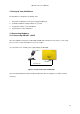
3.2.1 Power Supply
l Voltage Supply = 5V DC ±10%
l Current Supply = 150mA min.
3.2.2 External Interface
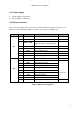
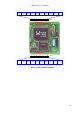
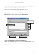
There is a total of 20 pins in the connector JP1 and JP2 in HD1321 to interface microprocessor,
Ethernet controller and UART with the user device. (See Table 3.1 and Figure 3.7)
Connector Pin # Symbols Descriptions Remarks
1 GND
Power Supply Grounding
2 Reset
System Reset Low Active
3 ~ 5 LED2 ~ LED0
Ethernet Communication Status LED
LED0: Tx, LED1: Rx, LED2: Collision
6 TPOut-
Ethernet Signal TPOut-
7 TPOut+
Ethernet Signal TPOut+
8 TPIn+
Ethernet Signal TPIn+
9 TPIn-
Ethernet Signal TPIn-
JP1
10 Vcc
5V Power Supply
1 Vcc
5V Power Supply
2 NC
3 DSR
RS232 Data Set Ready
4 CTS
RS232 Clear To Send
5 DTR
RS232 Data Terminal Ready
6 RTS
RS232 Ready To Send
7 RxD
RS232 Data Input
8 TxD
RS232 Data Output
9 NC
TTL Level
JP2
10 GND
Grounding
Table 3.1 HD1321 Pin Assignment