
Instruction Manual


HD132x Series User Manual
55
Appendix. RS232 Cable Connection
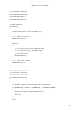
Signals of general RS232 9 pin connector:
Pin 1
Received Line Signal Detector (Data Carrier Detect) DCD
Pin 2
Received Data RxD
Pin 3
Transmit Data TxD
Pin 4
Data Terminal Ready DTR
Pin 5
Signal Ground GND
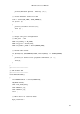
Pin 6
Data Set Ready DSR
Pin 7
Request To Send RTS
Pin 8
Clear To Send CTS
Pin 9
Ring Indicator RI
Table A. Signals of general RS232 9 Pin Connector
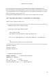
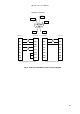
HD1320 and 1320E support RxD, TxD, RTS and CTS pins. If DTR and DSR are required for the flow
control, you can disconnect pins 1(DCD), 4(DTR), 6(DSR) of the RS232 connector as shown in Figure
6.1 to allow flow control communication with only RTS and CTS.
In case of HD1321, 5V TTL signal is provided for RS232 communication, and it supports RXD, TXD,
RTS, CTS, DTR and DRS signals.